7
AU
• STOPPING THE ENGINE
Emergency Stopping Procedure
. When it is necessary
to stop blower engine immediately, DEPRESS the switch
to STOP the engine.
Normal Stopping Method.
For normal stopping, release
trigger and allow engine to return to idle speed. Then
DEPRESS the switch to STOP the engine.
• STARTING A WARM ENGINE (Engine has
been stopped for no more than 15-20 minutes)
1. With throttle at IDLE (not depressed), pull starter rope
briskly.
2. If engine does not start, or starts and then stops after
5 rope pulls, follow procedure “6-1. STARTING A
COLD ENGINE”.
• BLOWER OPERATIONS
Your Talon blower is designed to easily remove debris
from patios, walkways, lawns, bushes, etc., and many
hard to reach areas where debris may accumulate.
DO NOT
operate the blower with other people or animals
in the immediate vicinity. Allow a minimum of 30 feet (9
meters) between operator and other people or animals.
We recommend that a face mask be worn when operating
blower in dusty areas.
Stand away from the debris, at a distance that will easily
allow you to control the direction of blown debris. Never
blow debris in direction of bystanders.
To control velocity of airstream, blower can be operated at
any speed between idle and full throttle. Experience with
the unit will help you determine the amount of airflow nec-
essary for each application.
• OPERATION INSTRUCTIONS
1. Follow the instructions “STARTING A COLD
ENGINE”.
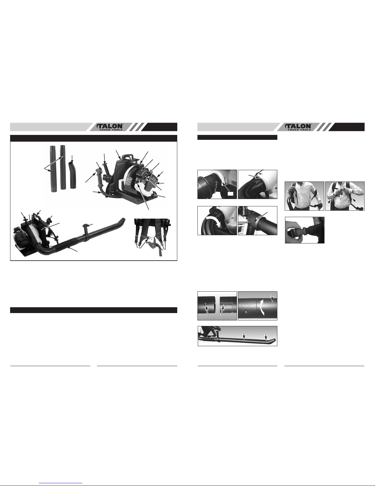
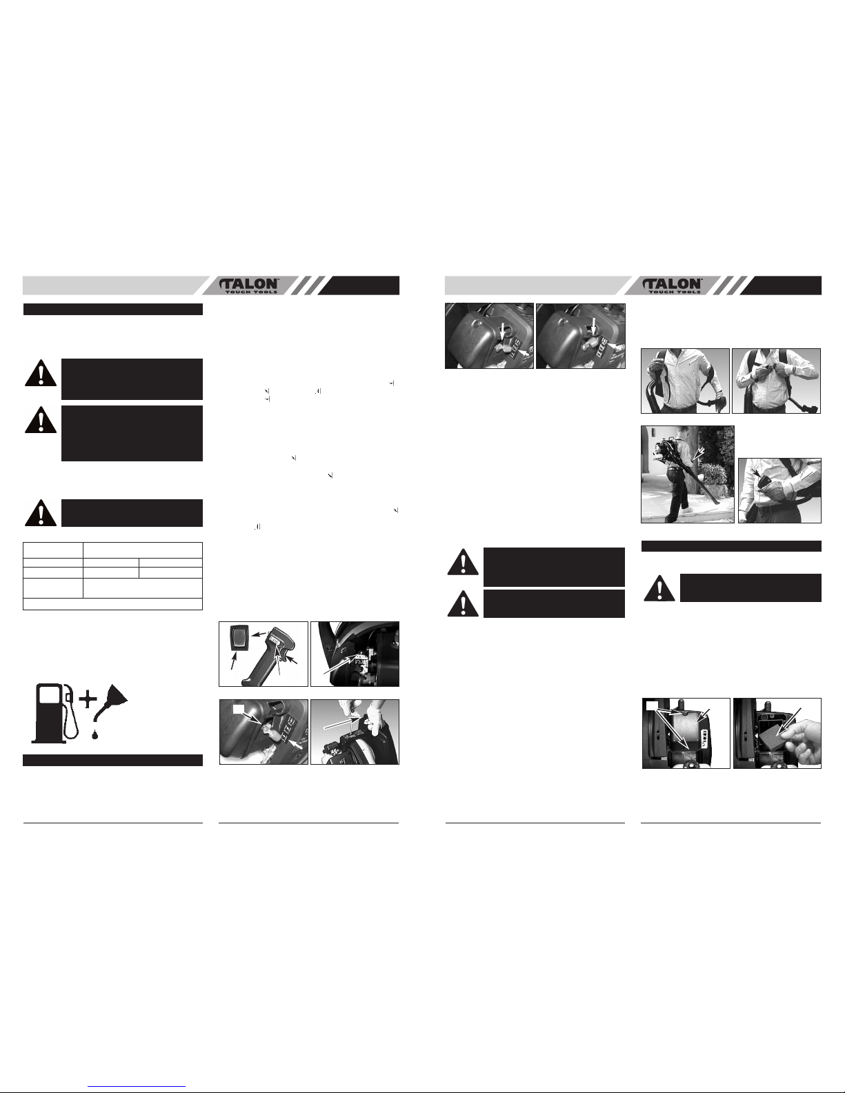
2. Once unit is running, place unit on your back by slip-
ping arms through the shoulder straps as if you were
putting on a jacket. Secure chest strap (Fig. 5A).
3. When preparing to clear an area of debris, always
position yourself so that you can control the direction
debris will be blown (Fig. 5B).
4. The pistol grip handle (A) and the flexibility of the
blower tube assembly will allow you to clear the most
hard-to-reach areas (Fig. 5B).
5. The hand grip, throttle trigger and stop switch (B) are
all mounted on a swivel handle that offers a wide
range of operating positions and comfort (Fig. 5C).
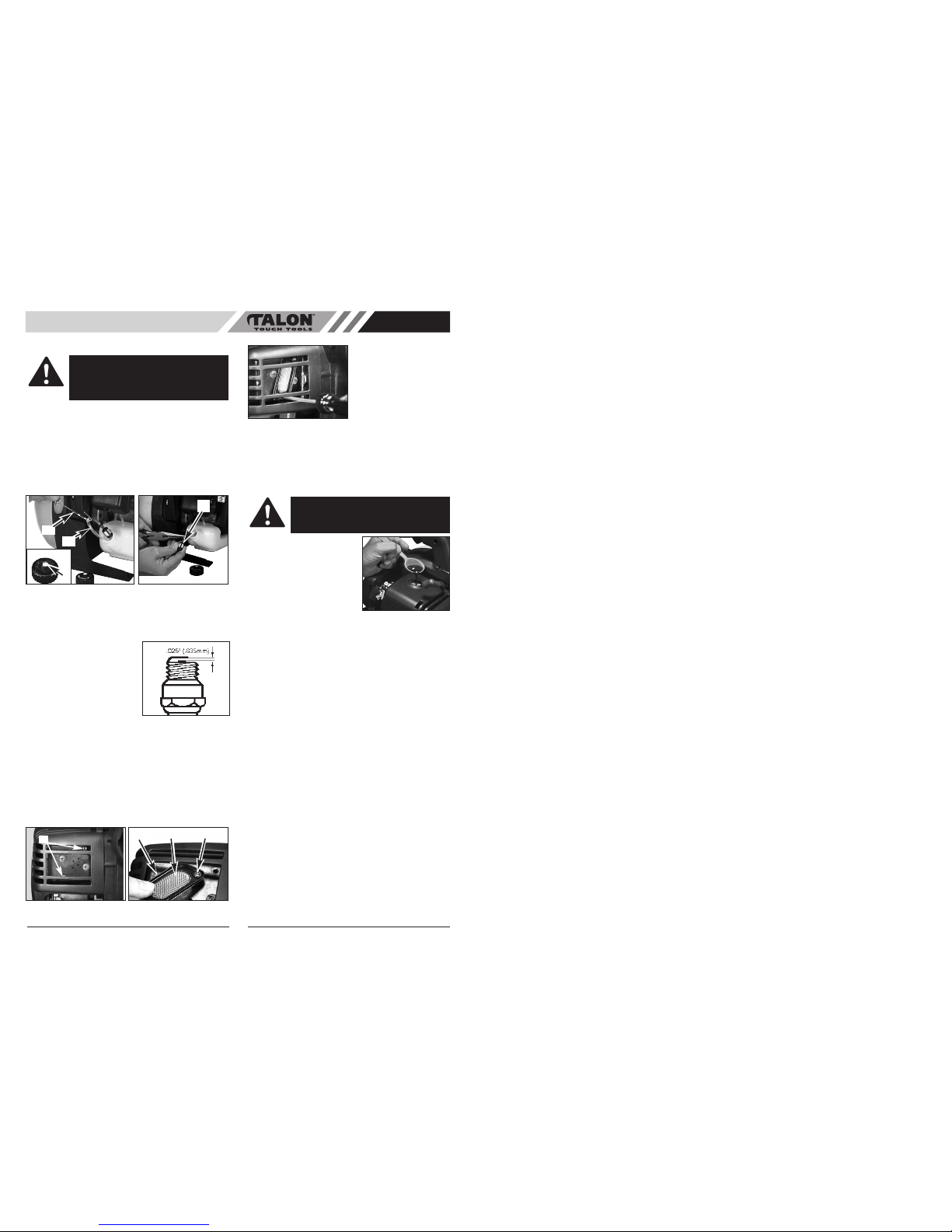
• AIR FILTER
To Clean Air Filter:
1. Remove 2 screws (A) holding air filter cover in place,
remove cover (B) and lift filter (C) from air box (Fig.
6A and B).
2. Wash filter in soap and water. DO NOT USE GASO-
LINE!
3. Air dry filter.
4. Reinstall air filter and air filter cover.
NOTE:
Replace filter if frayed, torn, damaged or unable to
be cleaned.
Fig. 4E Fig. 4F
Fig. 5A
Fig. 5B Fig. 5C
A
B
MAINTENANCE INSTRUCTIONS
CAUTION
: NEVER operate trimmer without
the air filter. The air filter must be kept clean.
If it becomes damaged, install a new filter.
WARNING:
Before using your blower, review
Safety Precautions in your User Manual, and
all regulations for operation of the unit. These
precautions and regulations are for your pro-
tection.
CAUTION:
Hold the blower so that hot exhaust
does not damage clothing and is not inhaled by oper-
ator.
Fig. 6A Fig. 6B
ABC
• FUEL
Use regular grade unleaded gasoline mixed with
2-cycle engine oil. Use mixing ratios in FUEL
MIXING TABLE.
• MIXING FUEL
Add the oil to an approved fuel container followed by the
gasoline to allow incoming gasoline to mix with oil. Shake
the container to ensure thorough mix.
• FUEL MIXING TABLE
• RECOMMENDED FUELS
Some conventional gasolines are being blended with oxy-
genates such as alcohol or an ether compound to meet
clean air standards. Your Talon engine is designed to
operate satisfactorily on any gasoline intended for auto-
motive use including oxygenated gasolines.
• FUEL AND LUBRICATION
• STARTING A COLD ENGINE
Fill fuel tank with proper fuel and oil mixture. See FUEL
AND LUBRICATION. Set unit on ground so that it rests on
the back pack frame.
1. Move ignition switch to the RUN “ I ” position (A). (Fig.
4A).
2. Set throttle lock (C): While holding trigger (B) at wide
open position, press down and hold throttle lock (C).
Release throttle trigger (B), then release throttle lock
(C). Throttle trigger (B) will now remain in the fully
depressed position (Fig. 4A).
3. Prime the carburetor. Pump the primer bulb (D) 10
times (Fig. 4B).
4. Your unit has a 3 position choke (E), CHOKE “ ”,
START “ ”, and RUN “ ”. Move choke lever to
CHOKE “ ” position (Fig. 4C).
5. Grip top assist handle (F) firmly (Fig. 4D).
6. Pull starter rope out a short way until resistance is felt
(approx. 100mm). A smooth rapid pull is required for
a strong spark. Pull starter rope until engine tries to
run but NO MORE THAN 4 TIMES. (Fig. 4D). If
engine starts and runs move choke lever immediate-
ly to the START “ ” position and follow instructions
on point 9. (Fig 4E)
7. Move choke lever to START “ ” position (Fig. 4E).
8. While trigger is still in the locked position pull starter
rope until engine starts and runs but NO MORE
THAN 4 TIMES. (Fig 4D)
9. Once engine starts leave the choke in the START “
” position for 10 seconds, then move the choke to
RUN “ ” position (Fig. 4F).
10. Squeeze trigger (B) to release throttle lock (Fig. 4A).
NOTE:
If engine fails to start after repeated attempts, refer
to Troubleshooting section.
NOTE:
Always pull starter rope straight out. Pulling starter
at an angle will cause rope to rub against the eyelet. This
friction will cause the rope to fray and wear more quickly.
Always hold starter handle when rope retracts. Never let a
rope snap back from extended position. This could cause
rope to snag or fray and also damage the starter
assembly.
6
AU
FUEL AND LUBRICATION
WARNING
:
Never use straight gasoline in
your unit. This will cause permanent engine
damage and void the manufacturer’s warran-
ty for that product. Never use a fuel mixture
that has been stored for over 90 days.
WARNING
:
Use a premium grade oil for 2-
cycle air cooled engines mixed at a 25:1
ratio. Do not use any 2-cycle oil product with
a recommended mixing ratio of 100:1. If
insufficient lubrication is the cause of engine
damage, it voids the manufacturer’s engine
warranty.
WARNING
: Lack of lubrication voids engine
warranty. Gasolilne and oil must be mixed at
25:1.
GASOLINE
5 Liters 6.7 oz. 200ml (cc)
1 lmp. Gal. 6.1 oz. 180ml (cc)
Mixing 25 Parts Gasoline
Procedure to 1 part Lubricant
1ml = 1cc
Gasoline and Oil
Mix 25:1
Fig. 4C Fig. 4D
F
E
Fig. 4A Fig. 4B
A
B
D
C
Talon 25:1 Ratio Custom Lubricant
OPERATING INSTRUCTIONS