TAMS B-2 User manual

n
n
n
nAnleitung
Booster B-2 nManual
nMode d´emploi
nHandleiding
n
Art.-Nr. 25-01-141 / 25-01-142 n
n

n
n
nDeutsch 3
nEnglish 26
nFrançais 49
nNederlands 72
n
n
n
n
n
n
n
n
n
© 10/2007 Tams Elektronik GmbH
Alle Rechte, insbesondere das Recht der
Vervielfältigung und Verbreitung sowie der
Übersetzung vorbehalten. Vervielfältigungen
und Reproduktionen in jeglicher Form
bedürfen der schriftlichen Genehmigung
durch die Tams Elektronik GmbH.
Technische Änderungen vorbehalten.
© 10/2007 Tams Elektronik GmbH
All rights reserved. No part of this
publication may be reproduced or
transmitted in any form or by any means,
electronic or mechanical, including
photocopying, without prior permission in
writing from Tams Elektronik GmbH.
Subject to technical modification.
© 10/2007 Tams Elektronik GmbH
Tout droits réservés, en particulier les droits
de reproduction et de diffusion ainsi que le
traduction. Toute duplication ou
reproduction sous quelque forme que ce soit
nécessite l´accord écrit de la societé Tams
Elektronik GmbH.
Sous réserve de modifications techniques.
© 10/2007 Tams Elektronik GmbH
Alle rechten voorbehouden. Niets uit deze
publicatie mag worden vermenigvuldigd
opgeslagen of openbaar gemaakt, zonder
voorafgaande schriftelijke toestemming van
Tams Elektronik GmbH.
Technische wijzigingen voorbehouden.
n

English B-2
Page 26
Table of contents
1. Why Boosters? 27
2. Getting started 27
3. Your B-2 29
4. Technical specifications 30
5. Safety instructions 31
6. EMC declaration 33
7. Safe and correct soldering 33
8. Assembling the kit 35
9. Splitting your model railway layout 41
10. Connecting the booster 42
11. Operation 44
12. Check list for troubleshooting 46
13. Manufacturer's note, CE and Warranty 47
Parts list I.1 / I.2
Circuit Diagram (Fig. 1) II
Printed Circuit Board (PCB) layout (Fig. 2) III.1
Drill stencil for heat sink (Fig. 3) III.2
Cut-out for housing (Fig. 4) III.2
Connections diagram (Fig. 5) IV
(Pages I to IV in the centre of this handbook are removable.)

B-2 English
Page 27
1. Why Boosters?
Boosters amplify the digital signals sent from the control unit and
supply a connected track with power.
You can measure the power consumption as follows:
§a locomotive: Gauge N: 600 mA / Gauge H0: 800 mA /
>Gauge 0: 1 A
§a wagon light: 50 - 200 mA
§another consumer (such as a sound module): 100 - 300 mA
§reserve for points: 10% of the calculated sum of power
consumption
The Booster B-2 can supply 3A. If your overall power demand exceeds
the capacity of one booster you have to connect additional boosters
according to the special requirements of your layout.
2. Getting started
How to use this manual
This manual gives step-by-step instructions for safe and correct
assembly of the kit and fitting of the ready-built device, and operation.
Before you start, we advise you to read the whole manual, particularly
the chapter on safety instructions and the FAQ chapter. You will then
know where to take care and how to prevent mistakes which take a lot
of effort to correct.
Keep this manual safely so that you can solve problems in the future. If
you pass the kit or the ready-built device on to another person, please
pass on the manual with it.

English B-2
Page 28
Intended use
The kit or the ready-built device can be assembled and operated with a
digital model railway using this manual.
Any other use is inappropriate and invalidates any guarantees.
The kit and the ready-built device should not be assembled or fitted by
children under the age of 14.
Reading, understanding and following the instructions in this manual
are mandatory for the user.
Checking the package contents
Please make sure that your package contains:
§one kit, containing the components listed in the parts and one PCB
or
§one booster B-2,
§one manual.
Required materials
For assembling the kit you need:
§an electronic soldering iron (max. 30 Watt) with a fine tip,
§a soldering iron stand,
§a tip-cleaning sponge,
§a heat-resistant mat,
§a small side cutter and wire stripper,
§a pair of tweezers and long nose pliers,
§tin solder (0,5 mm. diameter),
In order to connect the booster you need:
§wire. Recommended diameters: >0,10 mm² for the connections to
the push-button switch and the central unit and >1,5 mm² for the
connections to the transformer and the rails,
§transformer with 16-20 V voltage and minimum 3 A current
(minimum 50 VA).
B-2 English
Page 29
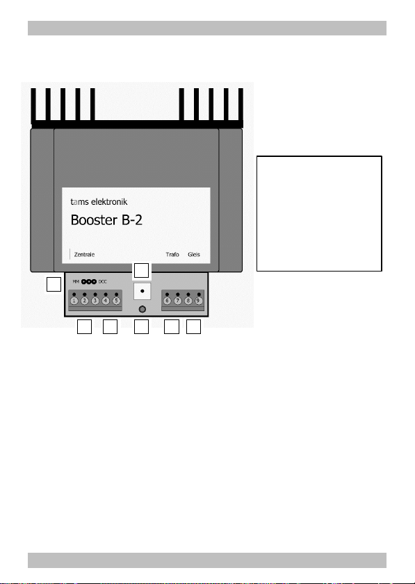
3. Your B-2
Data formats and ports
The B-2 is a multi protocol booster for your model railroad and capable
of amplifying data sent in the Motorola or the DCC format. It can be
connected either to the track port of a Motorola or DCC central unit, or
to a DCC-conforming booster port of a central unit.
Balanced track voltage
The booster B-2 is balanced, that means it keeps the power in a
connected track section constant on 18 V – independent of the actual
power consumption. This prevents changes in locomotive speeds and
the lightings´ brightness resulting from voltage variations.
1234
56
7
1Connection central unit
2Connection push-button
3Connection transformer
4 Connection track
5Setting MM / DCC
6Setting short-circuit
sensivity
7Operation display

English B-2
Page 30
Short-circuit protection
The short-circuit protection prevents damages to the booster, vehicles
and / or tracks, due to a derailed engine, for example. The sensivity of
the short-circuit protection has to be set on a trim-pot.
When a short circuit occurs at the track output, an internal current
limiter prevents damages to components of the booster and
automatically switches off the booster. The automatic short-circuit
switch-off can be cut off by bridging the push-button for switching-on
the B-2.
When the short-circuit warning wire is connected to the central unit,
the booster sends an overload signal to the central unit in case of a
short- circuit. Most central units then switch off the booster.
4. Technical specifications
Supply voltage 16-20 Volt alternating voltage (a.c.)
Input voltage 12-20 Volt digital voltage
Output voltage approx. 18 Volt digital voltage
Output current max. 3 A
Consumption max. 60 Watt
Protected to IP 00
Ambient temperature in use 0 - + 60 °C
Ambient temperature in storage -10 - + 80 °C
Comparative humidity allowed max. 85 %
Dimensions (including housing) approx. 114 x 99 x 42 mm
Weight of the circuit approx 93 g
Weight including housing approx 215 g

B-2 English
Page 31
5. Safety instructions
Mechanical hazards
Cut wires can have sharp ends and can cause serious injuries. Watch
out for sharp edges when you pick up the PCB.
Visibly damaged parts can cause unpredictable danger. Do not use
damaged parts: recycle and replace them with new ones.
Electrical hazards
§Touching powered, live components,
§touching conducting components which are live due to malfunction,
§short circuits,
§connecting the circuit to another voltage than specified,
§impermissibly high humidity,
§condensation build up
can cause serious injury due to electrical shock. Take the following
precautions to prevent this danger:
§Never perform wiring on a powered device.
§Assembling and mounting the kit should only be done in closed,
clean, dry rooms. Beware of humidity.
§Only use low power for this device as described in this manual and
only use certified transformers.
§Connect transformers and soldering irons only in approved mains
sockets installed by an authorised electrician.
§Observe cable diameter requirements.
§After condensation build up, allow a minimum of 2 hours for
dispersion.
§Use only original spare parts if you have to repair the kit or the
ready-built device.

English B-2
Page 32
Fire risk
Touching flammable material with a hot soldering iron can cause fire,
which can result in injury or death through burns or suffocation.
Connect your soldering iron or soldering station only when actually
needed. Always keep the soldering iron away from inflammable
materials. Use a suitable soldering iron stand. Never leave a hot
soldering iron or station unattended.
Thermal danger
A hot soldering iron or liquid solder accidentally touching your skin can
cause skin burns. As a precaution:
§use a heat-resistant mat during soldering,
§always put the hot soldering iron in the soldering iron stand,
§point the soldering iron tip carefully when soldering, and
§remove liquid solder with a thick wet rag or wet sponge from the
soldering tip.
Dangerous environments
A working area that is too small or cramped is unsuitable and can cause
accidents, fires and injury. Prevent this by working in a clean, dry room
with enough freedom of movement.
Other dangers
Children can cause any of the accidents mentioned above because they
are inattentive and not responsible enough. Children under the age of 14
should not be allowed to work with this kit or the ready-built device.
Little children can swallow small components with sharp edges, with
fatal results! Do not allow components to reach small children.
In schools, training centres, clubs and workshops, assembly must be
supervised by qualified personnel.
In industrial institutions, health and safety regulations applying to
electronic work must be adhered to.

B-2 English
Page 33
!
6. EMC declaration
This product is developed and tested in accordance with the European
standards EN 55014-1 and EN 61000-6-3 and meets the EC - directive
2004/108/EG and legal requirements.
To guarantee the electromagnetic tolerance in operation you must take
the following precautions:
§Connect the transformer only to an approved mains socket installed
by an authorised electrician.
§Make no changes to the original parts and accurately follow the
instructions, circuit diagram and PCB layout included with this
manual.
§Use only original spare parts if you have to repair the kit or the
ready-built device.
7. Safe and correct soldering
Caution:
Incorrect soldering can cause dangers through fires and heat. Avoid
these dangers by reading and following the directions given in the
chapter Safety instructions. If you have had training in soldering you
can skip this chapter.
§Use a small soldering iron with max. 30 Watt. Keep the soldering tip
clean so the heat of the soldering iron is applied to the solder point
effectively.
§Only use electronic tin solder with flux.
§When soldering electronic circuits never use soldering-water or
soldering grease. They contain acids that can corrode components
and copper tracks.
§Solder quickly: holding the iron on the joints longer than necessary
can destroy components and can damage copper tracks or
soldering eyes.
Table of contents


