Tanda TX7320 User manual

TX7320
Addressable Sounder
Installation and Operation Manual
TANDA UK Technology Copyright ©2015, All right reserved.

TX7320 Addressable Sounder
Installation & Operation Manual
4050100271-Rev1.0-1215
TANDA UK
Specifications are subject to change without prior notice
2
Product Safety
To prevent severe injury and loss of life or property, read the instruction carefully before installing the
Sounder to ensure proper and safe operation of the system.
European Union directive
2012/19/EU (WEEE directive): Products marked with this symbol cannot be disposed
of as unsorted municipal waste in the European Union. For proper recycling, return
this product to your local supplier upon the purchase of equivalent new
equipment, or dispose of it at designated collection points.
For more information please visit the website at www.recyclethis.info

TX7320 Addressable Sounder
Installation & Operation Manual
4050100271-Rev1.0-1215
TANDA UK
Specifications are subject to change without prior notice
3
Table of Content
1 Introduction .................................................................................................................................................. 4
1.1 Overview................................................................................................................................................ 4
1.2 Feature and Benefits........................................................................................................................... 4
1.3 Technical Specification ..................................................................................................................... 4
2 Installation ..................................................................................................................................................... 5
2.1 Installation Preparation ...................................................................................................................... 5
2.2 Installation and Wiring ........................................................................................................................ 5
3 Sounder Configuration .............................................................................................................................. 6
3.1 Preparation............................................................................................................................................ 6
3.2 Addressing ............................................................................................................................................. 6
3.3 Single and Dual Address Mode....................................................................................................... 7
3.4 Typical and Saving Mode ................................................................................................................. 8
3.5 Sounder Type ........................................................................................................................................ 8
3.6 Tones Selection..................................................................................................................................... 9
3.7 Read Configuration .......................................................................................................................... 10
4 General Maintenance ............................................................................................................................ 11
5 Troubleshooting Guide ............................................................................................................................ 11
Appendix 1..................................................................................................................................................... 11
Operational Performance Data for LPCB Approved Tones......................................................... 11
Limitation of Sounder Device................................................................................................................ 12

TX7320 Addressable Sounder
Installation & Operation Manual
4050100271-Rev1.0-1215
TANDA UK
Specifications are subject to change without prior notice
4
1 Introduction
1.1 Overview
The TX7320 Addressable Sounder is alarm warning device used to notify persons in the vicinity of the
occurrence fire emergency in order the person to take appropriate measures. The unit adopt multi-
application device starting from the types, parameters and wiring layout in single unit. Parameters
can be configured according to the requirement which include alarm tone from 17 different tones,
single address or dual address mode and also setting of power mode to low current consumption in
a simple programing.
The unit manufactured base on the requirement of EN 54 part 3, European Standard. The unit is
aesthetically pleasing with unobtrusive design that will complement modern building designs and its
plug-in type assembles make installation and maintenance more convenient to the installer. The unit
is compatible to the TX7004 Analogue Intelligent Fire Alarm Control Panel, produced by single
manufacture T&A, to avoid addressable communication compatibility problem.
1.2 Feature and Benefits
EN54-3 Compliance
Built-in MCU processor and digital addressing
17 tones Programmable sound output
Programmable Evacuate or Pre-alarm/Evacuate signal
Low and normal consumption mode
One or Two addresses mode
Onsite Adjustable Parameters
Loop or external power input
Aesthetically pleasing design
Universal mounting with fix base for simple installation
1.3 Technical Specification
Listed LPCB Pending
Compliance EN54-3
Input Voltage Loop Power: 24VDC [18V to 27.5V]
External PSU: 24VDC [20V to 27.5V]
Typical Current Loop: Standby 0.6mA, Alarm: 1.4mA
[Loop and External PSU] External PSU: Standby 0.6mA, Alarm: 10mA
Saving Current Standby 1.2mA, Alarm: 4mA
[Loop powered]
Protocol/Addressing T&A, Value range from 1 to 254
Address Sequence Single Address: Evacuate tone
Dual Address: 1st Alert Tone / 2nd Evacuate tone
Material / Colour ABS / RED Glossy finishing
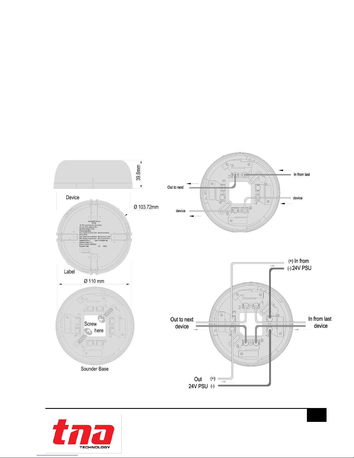
Dimension / Height Diameter 110 mm / 39.6 (with Base)
Weight 180g (with Base), 114g (without Base)
Class Type A, Indoors
Operating Temperature -10°C to +50°C
Ingress Protection Rating IP21
Humidity 0 to 95% Relative Humidity, Non condensing

TX7320 Addressable Sounder
Installation & Operation Manual
4050100271-Rev1.0-1215
TANDA UK
Specifications are subject to change without prior notice
5
2 Installation
2.1 Installation Preparation
This alarm warning device must be installed, commissioned and maintained by a qualified or factory
trained service personnel. The installation must be installed in compliance with all local codes having
a jurisdiction in your area or BS 5839 Part 1 and EN54.
2.2 Installation and Wiring
1. Mount the sounder base on standard one [1] gang electrical back box. Follow the arrow
mark for the correct position. Do not over-tighten the screws otherwise the base will twist. Use
M4 standard screws.
2. Connect the wire in terminal as shown in Figure [2&3]. Verify the device number or other
device parameters if desired using handheld programmer then stick on the label before
attaching sounder. The sticker labels are available on the control panel.
3. Attach the sounder to the base, point the sounder in the base by the mark-line and secure
the sounder in that position by rotating it clockwise, until it reaches the next mark line.
Figure 2: Loop Powered
Figure 1
Figure 3: With External Supply
Terminal Description
1Signal In (+)
2Signal Out (+)
3External PSU In (+) Optional
4External PSU Out (+)Optional
5Signal In (-)
6Signal Out (-)
7External PSU In(-)Optional
8External PSU Out (-)Optional

TX7320 Addressable Sounder
Installation & Operation Manual
4050100271-Rev1.0-1215
TANDA UK
Specifications are subject to change without prior notice
6
Figure 4
Figure 5
Figure 6
Figure 7
3 Sounder Configuration
3.1 Preparation
The TX7930 handheld programmer is used to configure sounder soft address and parameters. This
tools are not included, must be purchased separately. The programmer is packed with twin 1.5V AA
battery and cable, ready for usage once received.
It is mandatory for the commissioning personnel to have programmer tool in order to adjust the
sounder conferring to the site situation and environmental requirements.
Program a unique address number for each device according to the project layout before placing
from the Terminal Base.
Warning: Disconnect the loop connection whilst connecting to the handheld programmer.
3.2 Addressing
1. Connect the programming cable to Z1
and Z2 terminals (Figure 4). Press “Power”
to switch on the unit.
2. Switch-on the programmer, then press
button “Write” or number “2” to enter
Write Address mode (Figure 5).
3. Input the desire device address value
from 1 to 254 and then press “Write” to
save the new address (Figure 6).
Note: If display “Success”, means the
entered address is confirmed. If display
“Fail”,means failure to program the
address (Figure 7).
4. Press “Exit”key to go back Main Menu. Press “Power”key to switch-off the programmer.
1. Read
2. Write T
3. R/W Config 7
4. Set
Address: 001
Next Address: 002
Success
Address: 003
Fail

TX7320 Addressable Sounder
Installation & Operation Manual
4050100271-Rev1.0-1215
TANDA UK
Specifications are subject to change without prior notice
7
Figure 8
Figure 9
3.3 Single and Dual Address Mode
Single address is commonly used to program immediate Evacuate tone while the dual
address used for programming Pre-alarm and Evacuate tones respectively in a given period
of time.
In Single Address Mode
When in action (Evacuation stage), the sounders will produce simultaneously audible signal
according to the pre-defined tone (Table 1- Tone 14 is the default tone) and will stop if the
panel is reset.
In Dual Address Mode
When In action the 1st Address sounder (Pre-alarm Stage), will produce simultaneously
audible signal according to the pre-defined tone (Table 1- Tone 17 is the default tone). This
will run continuously according to the pre-defined time unless the panel is being reset before.
When the delay time is over the 1st address sounder will stop then immediately, the 2nd
address sounder (Evacuate Stage) will produce simultaneously audible signal according to
the pre-defined tone (Table 1- Tone 14 is the default tone) and will stop if the panel is reset.
1. Attach the programming cable to 1 and 6 Terminals of sounder. Press “Power” to switch-on
the unit.
2. Switch-on the programmer, then press button “3” to enter to Configuration mode (Figure 8).
3. Input the “1”for Single Address mode or “2”for Dual Address mode then press “Write” to
change the setting into the desire mode (Figure 9).
Note: If display “Success”, means the entered mode is confirmed. If display “Fail”, means
failure to program the mode.
In Dual address mode, the sounder will generate the unique next higher number for the
second address for example: In single address mode the address number is 15, when change
to dual address mode the address numbers will now be 15 and 16.
Warning: Dual address mode may cause Duplicate address fault on the panel and may
affect the operation of the next device with conflicted address number if not carefully
arrange the loop addressing.
4. Press “Exit” key to go back Main Menu. Press “Power” to switch off the programmer.
1. Read
2. Write T
3. R/W Config 7
4. Set
①Single ②Dual
③Typ ④Saving
⑤Strobe ⑥Sound
Configure Description
①Single [Default]
②Dual

TX7320 Addressable Sounder
Installation & Operation Manual
4050100271-Rev1.0-1215
TANDA UK
Specifications are subject to change without prior notice
8
Figure 10
Figure 11
3.4 Typical and Saving Mode
When Sounder is configured to Saving Mode the recommended wiring is loop powered
[Figure 2] within the limit of 20 units per loop and subject to the total calculated current load
in particular loop. If Sounder is configured to Typical Mode, it requires external power supply
[Figure 3] installer should consider additional power cable.
1. Attach the programming cable to 1 and 6 Terminals of sounder. Press “Power” to switch-on
the unit.
2. Switch-on the programmer, then press button “3” to enter to Configuration mode (Figure 10).
3. Input the “3”for Typical mode or “4”for Saving mode then press “Write” to change the
setting into the desire mode (Figure 11).
Note: If display “Success”, means the entered mode is confirmed. If display “Fail”, means
failure to program the mode.
Warning: Under saving mode loop powered up to 20 sounder maximum per loop is the
recommended.
4. Press “Exit” key to go back Main Menu. Press “Power” key to switch off the programmer.
3.5 Sounder Type
1. Attach the programming cable to 1 and 6 Terminals of sounder. Press “Power” to switch-on
the unit.
2. Switch-on the programmer, then press button “3” to enter to Configuration mode (Figure 12).
3. Input the “5”for Strobe type or “6”for Sounder type, then press “Write” to change the setting
into the desire mode (Figure 13).
Note: If display “Success”, means the entered type is confirmed. If display “Fail”, means
failure to program the type. No use for TX7320 to select Strobe Mode.
4. Press “Exit” key to go back Main Menu. Press “Power” key to switch off the programmer.
1. Read
2. Write T
3. R/W Config 7
4. Set
Read Description
③Typ: Typical mode, the
sounder device consume
4mA [Default]
④Saving: Low current
consumption at 4mA
①Single ②Dual
③Typ ④Saving
⑤Strobe ⑥Sound

TX7320 Addressable Sounder
Installation & Operation Manual
4050100271-Rev1.0-1215
TANDA UK
Specifications are subject to change without prior notice
9
Figure 12
Figure 13
3.6 Tones Selection
The Tones can be change according to the project requirement
Table 1
Parameter
Tone
Code
dB(A) Output
(low)
dB(A) Output
(high)
Description
1
01
98.9
95.7
970Hz
2
02
100.9
96.6
800Hz / 970Hz @ 2Hz
3
03
102.9
99.3
800Hz -970Hz @1Hz
4
04
99.7
97.4
970Hz 1s off / 1s on
5
05
101.3
98.7
970Hz, 0.5s / 630Hz, 0.5s
6
06
102.7
98.8
500Hz - 1200Hz×3, 3.5s on / 0.5s off
7
07
106.6
101.4
2850Hz, 0.5s on / 0.5s off×3 / 1.5s off
8
08
106.1
102.3
2850Hz 0.4s on, 0.3s off
9
09
99.7
96.6
550Hz, 0.7s / 1000Hz, 0.33s
10
10
105.7
100.8
1500Hz -2700Hz @ 3Hz
11
11
102.3
97.0
2400Hz
12
12
102.4
97.0
500Hz -1200Hz @ 0.33Hz
13
13
104.4
100.6
2400Hz -2900Hz @ 9Hz
14
14
105.7
102.0
2400Hz -2900Hz @ 3Hz [Default]
15
15
102.0
99.2
800Hz-970Hz @ 3Hz
16
16
102.1
98.8
500Hz-1200Hz, 3.75s / 0.25s off
17
17
101.3
98.7
800Hz 1s off / 1s on [Pre-alarm]
1. Read
2. Write T
3. R/W Config 7
4. Set
Read Description
⑤Strobe: Visible signal only
⑥Sound: Audible signal only
Note: Select 5 and 6 for both
visible and audible signal.
[Default 5 and 6] No use for
TX7320 to select Strobe
Mode.
①Single ②Dual
③Typ ④Saving
⑤Strobe ⑥Sound

TX7320 Addressable Sounder
Installation & Operation Manual
4050100271-Rev1.0-1215
TANDA UK
Specifications are subject to change without prior notice
10
Figure 14
Figure 15
Figure 16
Figure 17
Figure 18
1. Attach the programming cable to 1 and 6 Terminals of sounder. Press “Power” to switch-on
the unit.
2. Switch-on the programmer, then press button “4” to enter to Setting mode (Figure 14). The
programmer will display the actual configuration after few seconds.
Input the desire Tone (Table 1) then press “Write” to change the setting (Figure 15).
Note: If display “Success”, means the entered tone is confirmed (Figure 16). If display “Fail”,
means failure to program the tone (Figure16). Tone 14, Tone 16 and Tone 17 are recognized
by LPCB.
3. Press “Exit” key to go back Main Menu. Press “Power” to switch off the programmer.
3.7 Read Configuration
1. Attach the programming cable to 1 and 6 terminals of sounder. Press “Power” to switch on
the unit.
2. Switch-on the programmer, then press button “Read” or “1” to enter to Read mode (Figure
17). The programmer will display the configuration after few seconds. (Figure 18).
1. Read
2. Write T
3. R/W Config 7
4. Set
Tone: 001
Success
Tone: 001
Fail
1. Read
2. Write T
3. R/W Config 7
4. Set
Address: 123,124
Tone: 008
ID: 123456789012
Read Description
Address: Unique number
assigned
Note: Single address displays
one address while dual
addresses display two
addresses
Tone: selected audible tone
ID: Device serial number

TX7320 Addressable Sounder
Installation & Operation Manual
4050100271-Rev1.0-1215
TANDA UK
Specifications are subject to change without prior notice
11
4 General Maintenance
1. Inform the suitable personnel before conducting the maintenance.
2. Disable the alarm warning device on the control panel to prevent false alarm.
3. Do not attempt to repair the circuitry of the alarm warning device, it may affect the
operation to respond to a fire condition and will void the manufacturer’s warranty.
4. Use a damp cloth to clean the surface.
5. Notify again proper personnel after conducting the maintenance and make sure to enable
the alarm warning device and confirm if up and running.
6. Perform the maintenance on semi-annually or depending on the site conditions.
5 Troubleshooting Guide
What you notice
What it means
What to do
Address not enrolling
The wiring is loose
The address is duplicate
Conduct maintenance
Re-Commission the device
Unable to commission
The damage the electronic circuit
Replace the device
Appendix 1
Operational Performance Data for LPCB Approved Tones
1. Tone 14 –Volume dB(A)
Normal Mode
Low Current Consumption
Angle
Horizontal Plane
Vertical Plane
Horizontal Plane
Vertical Plane
Max27.5V
Min 20V
Max27.5V
Min 20V
Max27.5V
Min 18V
Max27.5V
Min 18V
15°
92.1
87.8
95.8
91.2
84.8
86.6
83.9
84.1
45°
93.1
88.6
96.7
91.7
84.8
83.6
89.0
88.6
75°
96.5
92.7
101.1
97.1
88.1
89.2
90.8
89.2
105°
94.5
90.2
101.3
96.1
86.2
84.8
91.2
90.1
135°
91.7
86.9
99.4
94.6
84.8
82.2
84.9
84.2
165°
89.6
84.9
97.8
93.3
83.5
84.1
84.7
84.0

TX7320 Addressable Sounder
Installation & Operation Manual
4050100271-Rev1.0-1215
TANDA UK
Specifications are subject to change without prior notice
12
2. Tone 16 –Volume dB(A)
Normal Mode
Low Current Consumption
Angle
Horizontal Plane
Vertical Plane
Horizontal Plane
Vertical Plane
Max27.5V
Min 20V
Max27.5V
Min 20V
Max27.5V
Min 18V
Max27.5V
Min 18V
15°
89.4
84.8
89.6
85.3
83.4
80.0
83.8
80.7
45°
89.8
85.6
94.0
90.0
84.8
82.0
87.3
84.3
75°
91.2
86.8
95.6
91.7
86.8
84.0
88.0
85.3
105°
91.7
87.3
96.7
92.4
83.9
81.6
85.0
82.1
135°
90.0
86.0
90.5
86.2
83.4
79.9
87.9
85.5
165°
86.7
82.9
90.9
86.6
80.4
77.6
83.4
80.5
3. Tone 17 –Volume dB(A)
Normal Mode
Low Current Consumption
Angle
Horizontal Plane
Vertical Plane
Horizontal Plane
Vertical Plane
Max27.5V
Min 20V
Max27.5V
Min 20V
Max27.5V
Min 18V
Max27.5V
Min 18V
15°
87.3
85.1
89.3
98.0
76.7
76.1
76.1
77.3
45°
87.3
83.9
86.7
84.4
75.4
76.8
81.0
81.2
75°
84.2
81.1
94.3
90.9
81.9
83.7
81.4
82.8
105°
84.1
82.4
90.9
87.7
79.5
81.2
79.4
80.2
135°
89.7
87.6
87.5
85.3
79.7
82.0
85.2
86.2
165°
89.4
87.2
91.2
88.9
80.8
82.3
76.6
77.2
Limitation of Sounder Device
The alarm warning device cannot last forever. In order to keep the alarm warning device working in
good condition, please maintain the equipment continuously according to recommendations from
manufacturers and relative nation codes and laws. Take specific maintenance measures on the
basis of different environments.
This alarm warning device contains electronic parts. Even though it is made to last for a long period
of time, any of these parts could fail at any time. Therefore, test your alarm warning device at least
every half-year according to national codes or laws. Any fire alarm devices or any other
components of the system must be repaired and/or replaced immediately as they fail.
Table of contents
Popular Fire Alarm manuals by other brands

FireClass
FireClass Precept EN Panel Installation & commissioning manual

Cooper Notification
Cooper Notification E70-24MCW Series installation instructions

SilentCall
SilentCall SK2-SS Sidekick II Signature Series user guide

LY International Electronics
LY International Electronics M-9000 Series user manual

Tyco
Tyco F3200 Installation & programming manual

Monaco
Monaco C-99A Installation, operation, maitenance manual

Potter
Potter FFT-1000 installation manual

Honeywell
Honeywell NOTIFIER ONYX FirstVision Installation and operation manual

Bosch
Bosch FMM-7045 installation instructions

Fike
Fike FCP-300 Installation & operation manual

Honeywell
Honeywell XLS140 installation manual

Gira
Gira 1141 Series Installation and operating instructions