TANDBERG TCD 340A User manual

TANDBERG
^ TCD
34OA-
Circuit
DagraTs
wrth
A
li
gnrn
en
tTn
st
r
u
cti
o
n
s
Mechanical
adjustments,
see
Service
Manual
for TCD
330,
Ordering
No. 714021

Electrical
adjustments
for the TCD 3404
General
Before
adjusting,
the tapepath mustbe cleaned
and demagnetized.It is necessary
that the tape
path is correctly adjusted, consult the service
manual
forthe
TCD330,part
No. 714021.
Carry
out theadjustments
in theorderdescribed
becausetheadjustments
affect
eachother.Remove
thetop panel,base
panel,
and
right side
panel.
Equipment
required
- 2volt meters
- Audio signal
generator
- Frequency
counter
- Distortionmeter
- Wowand
flutter meter
- Tandberg
testcassettes
- No.21
(Speedcheck,1000Hz)
- No.22(Wow
and
flutter
check,3150Hz)
- No.23(Azimuth
adj.playb.head,6300Hz)
- No. 24 (Playback
level
adj.,1000Hz)
- Measuringcassettes
- Maxell
UD XL I (TypeI)
- Maxell
UD XL Il (Type
II)
Beforeadjusting,
set
the buttons to:
- MPX-FILTER (situated
at thebackof the deck)
to OFF.
- Dolby NR* to Off.
- Tapeto Type
I.
- Output Level
controlsto max.
* The word "Dolby" is registeredtrade marh
of Dolby Laboratories
Inc., USA.
NR stands
for l'{oiseReduction.
Oscillator
The
oscillator
frequency
is
between
80and
100
kHz.
Thevoltage
measuredon theerase
headshould
be
between
25 and32volts.
Sensitivity
adiustment
- Set
theMonitor button to Sourceposition,
and
Input andOutput Level
controls
to maximum.
- Apply 8mV,1000
Hz to the
RADIO socket
(DIN)
or 80mV,l000 Hzto theINPUTsockets
(Phono)
from the audiosignal
generator.
- Adjustthe
SENSITIVITYADJ.pots.Rl01-R201
to obtain 775 mY measuredon avoltme
tercon-
nected
to theDolby encoderoutput,
see
Figure
1.
- Move
themeasure
probe
to theDolby decoder
output, see
Figure
2.
- Adjust the SOURCE
LEVEL ADJ. pots.
Rl18-
R218
to obtain775 mV
.
- Checkthe frequencyresponsein Source.
Dolby encoder output
Rightchannelmeas.point Left channel
meas.point
_ | RroBP I Prosr.
.:.,
P)lI P I RTL LLvtL T'Pf I TAPI
REc METER J- - - -l
R2rg
R RrrBL R2oqRa agrog !
aori*aa a?ura REcLEV€LaoJ TYPE
tl TAPE
TRIMMING POIS ON MAIN AOARD SE€N FAOM SOLOER SIDE
Figure
1 Trimming
pots.
andDolby encoderrneasurement
points

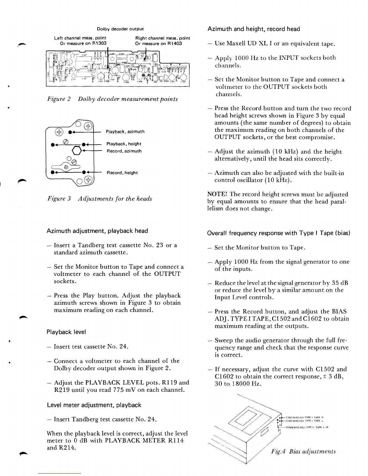
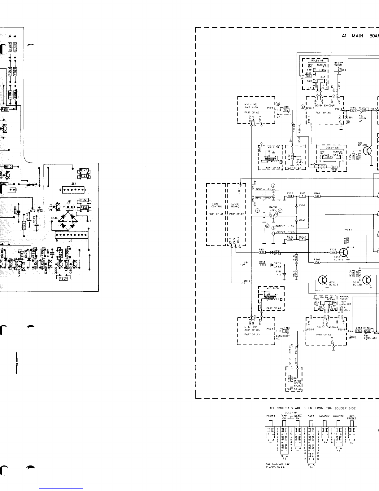
Figure2 Dolby decodermeasurern,entpoints
Playback,azimuth
Playback,height
Record,
azimuth
Record,height
Figure3 Adjustmentsfor the heads
Azimuthadjustment,
playback
head
- Inserta Tandberg
test cassette
No. 23 or a
standardazimuth
cassette.
- SettheMonitor button to Tape
andconnecta
voltmeter to each channel of the OUTPUT
sockets.
- Press
the Play button. Adjust the playback
azimuth screws
shown in Figure 3 to obtain
maximumreadingon eachchannel.
Playback
level
- Insert
testcassette
No. 24.
- Connect
a voltmeterto each
channel
of the
Dolby decoderoutput shown
in Figure
2.
- AdjustthePLAYBACKLEVEL pots.
Rl19 and
R219until you read775mV on each
channel.
Levelmeteradjustment,
playback
- InsertTandbergtestcassetteNo. 24.
Whenthe playback
leveliscorrect,adjustthelevel
meterto 0 dB with PLAYBACKMETER Rl14
andR214.
Azimuth and height,record head
- UseMaxell UD XL I or an equivalent tape.
- Applf' 1000 Hz to the INPUT sockcts
both
channels.
- Set the Monitor button to Tape and connect a
voltmeter to the OUTPUT socketsboth
channels.
- Press
the Record button and turn the two record
head height screwsshown in Figure 3 by equal
amounts (the samenumber of degrees)to obtain
the maximum reading on both channels
of the
OUTPUT sockets,or the best compromise.
- Adjust the azimuth (10 kHz) and the height
alternatively, until the head sitscorrectly.
- Azimuth can alsobe adjusted with the built-in
control oscillator(10 kHz).
NOTE! The record height screws
must be adjusted
by equal amounts to ensure that the head paral-
lelism doesnot change.
Overall
frequency responsewith Type I Tape (bias)
- Set the Monitor button to Tape.
- Apply 1000 Hz from the signalgeneratorto one
of the inputs.
- Reducethe levelatthe signal
generatorby 35 dB
or reduce the levelby a similar amount on the
Input Level controls.
- Press
the Record button, and adjust the BIAS
ADJ. TYPE I TAPE, C1502andCl602 to obtain
maximum readingat the outputs.
- Sweep the audio generator throush the full fre-
quency rangeand check that the response
curve
is correct.
- If necessary,
adjust the curve with C1502 and
C1602 to obtain the correctresponse,
t 3 dB,
30 to 18000 Hz.
-'.\
Dolby decoderoutpul
Left channel
meas,
point
Or measure
on 81303 Right
channelmeas.
point
Or measureon R1403
i^
..^O
o^v^
^Va
.J n.':
\ -v/-
o<-o
^Biasadjustments

Adjusting
the record
current(Source/Tape) Distortion
Type I Tape Record1000
Hz at 0 dB deflectionon themeters. I
- Use
the sameinput levelas
for thebiasadjust- The max. distortion for record/playback
is 3%.
ment
(- 35dB)
and
1000Hz.
- Adjust the recordcurrentby means
of the Erase
test
REC.LEVEL ADJ.pots.Rl08 and
R208
to
obtainthesameoutput level
for both positions Connect a microphone to the TCD 3404 and \
on theMonitor butron. recordanoverloadsignal.Recordagain
to erase
the
overloadrecordingand play back to ensure
that
- Thendepress
theDolby NR button andcheck the overloadsignalcannotbeheard. c
the overallfrequencyresponse.
Az
imuth meter
adjustment
Overall
frequencyresponse
with Type ll Tape
(bias) - Set
thebuilt-in oscillator
to ON.
- Use
thesame
procedureas
for theTypeI tape. - SettheOutput Level
controls
to maximum.
- Insert
aMaxellUD XL II or ancquivalenttape. - Insert
aTypeI tapeand
press
theRecord
button.
- Setthe Tapebutton to Type II position,and /
press
the Record
button. - Adjust p.Z2Z
(AZIMUTH METER ADJ.) to
- check the frequencyresponse,andif necessary, ff.or:"r:t-"tely - 3 dB deflection on the right
adjustthe BIAS ADJ. TYPE II TAPE, pot.
Rl 508
to obtainthecorrect
response. _ Checkalsothat the meterdeflection
with a
Type II tapeis
within themeter
scale.
Adjustingtherecordcurrent(Source/Tape)
Typell Tape Speed
check
- Usethesameinput level
asfor the biasadjust-
ment
(- 35
dB)
and
1000IIz. Play
backTandberg
test
cassette
No. 21 (speed
check 1000Hz) andmeasurewith a frequency
- Adjusttherecordcurrentby meansof the REC. counter
on theOUTPUTsockets:
LEVEL ADJ.pots
Rl09 and
R209
to obtain
the <! 03% (995
to 1005Hz).
sameoutput level
for both positionson the
Monitor button. Wow
andflutter
R1101andR1201affectthetreble
response
in I
thefrequencyregion15-18 kHz on theplayback Play back a Tandbergtest cassetteNo. 22
curveforall typesof tapes. (3150 Hz) and measurewith a wow and flutter
meter
on theOUTPUTsockets:
Level
meters
adjustment,
record weightedRMS:( 0.09%
WeightedPeak
DIN 45511 10.2%
- SettheMonitor button to Tape' Record/prayback
- Apply 1000Hz to the INPUT sockets
(both Recordfrom a generator31b0 Hz (check
with a
channels)' frequency.or,ni., andmeasure
with the wow and
flutter meteron theOUTPUTsockets.
- Press
the Recordbutton and adjustthe Input
Level controls for 1.5 volt ,.uiing on thi weightedRMS:( 0'12%
OL-rTPI-IT
sockets.
- Adjustthe
REC.METERpots.
Rl13 and
R213
to obtain0 dB on thelevelmeters.
g
Al

,
!^
^
r-- -----l
; A4 EOUAL
REC AMP (NOTES
I-4) I
alaL
:5588
lo!
0705
BC5488
L-
PART
A1
= Lla c. I
r_=;l l{ ----J
\\ |
.-:=l fr;--'l Lu"Les. ctarnwsrspEsrFrE!,REssrANcErNoHMs
: :^t !i 1 I eLur, rERMNAL |o's FoR TsE R C8ANNEL aRE c vEN N
"cr _tl-+:r-, I BplchFls EEsloE IHE L CHANNEL
PLlo llRM NrL ills
.la rero Ll,' | 3.,-,rr*ur. ia5 r0r,rse. aND R cnANlrL Hssor d99as
- ! IAPE .r l: I ctMp!.!F!T !o s WHEN RFFER|N6ID R CFANNELcoMpoNEtt
I I ADD tL) Tt TfE L CiANNEL ND5 IEG n70r 0F THr
] I L CH3KNIL dA5 lHE SAME VALUE45 RSOI
CF TNE R CH
PART OF i | 4. cs,o ;zn JN EURoIEAN MooELs
o r---{FFi7l-<
.---.1RAnqf< -qdUU
-+
a
.--1&.]-zj- EFI
'--L5.9.]LI- Fmsl ?l*
| 3.*u {oeot *-{Es2n]-. ,--rurrl--.
I'
-Iceoi -.{F:dgi}- oeosp L8;)a$a I
a - - .t{l= .ttl =^-.-
/ Ic804
F{F807F{ O80sk a -E ?
o--{n6btrL+ "o9
- = ^.() elneosl< .-@- --@-
ru.-gg1f- e ----E;;r1-
M - >_lnTril_+
--@;""9 ._@-. g *Fn3]-
Ldu/T *ffi-. fce,z u ",r, l
r *m- ,.,oisl illilt
rHl-1 t-lR8olF{ |
A2 5oro o\LlvDtt
I
_ll
*q-m1-.
.+ iF --m;-^!"f T diTii@_-
+__lnn
r......._l<
.c.t1t.C71zB I t\
.---1Frrr- + + '1x' --lalool--. *@*-
--i#- *@- &'-@-
J,,-_{Rf19}-- Tc70.r
e{nrtdr- = --EjlI-
a
olaL)ry ,qo7o5 ,,c7oe ]fl!- r@- r
{ € *iF"" *E}- g t.,.
l-rz :-l P 1't G-F@{ TcTos
li..l I 6 3 I .+
rfttatafl
J4o iiiiit+ti *€zG- .-'-_'
I
J
tE? l
I
I
I
! l r--,:
oF l:li ;
i lJill'
crorl{ffif
fA F""l I
EIE[:li]
| Fldl
"T
T ],,.I-
^
A4 EOUAL
REC.AMP.

wTs -- --S*--Et* + #u.* I*l I"El*
. e< lP- -fl,hj,
t ,h!, it lilTFlt
,E,E'--w .----.----
F-JlT.tT
G. ll '" -'--I
nrprnrr*,n*;
"9it la"a - -
TI
I ,t
"+ffHs{
A1 MAIN
BOARD A
^

a
A
rgr
I
J
ta
I
H
I
EI
TI
t
I
Itl
T
t
IEI
T
r
I
I
I
{
.K)
F
4
- .Lsr .g^.. r*l l# ?
3l_
_:ElilrEI
g3+;Fts
I
ilBffiJE&ASHSI
;@oo
9FaO- L@J
P20 il
I
:l
-11.r
I
r
I
I
I
I
I
I
I
I
I
I
I
I
I
I
I
I
I
I
I
I
I
I
I
I
I
I
I
I
I
I
I
I
I
I
I
I
I
I
I
I
I
I
I
L
A1 MAIN BOAF
t-------1
-;.i;lr t-tr
tt_J ll
ll;
E!t
F--tr--+''r
*?
8*
*l ao
\/W{WT?
tEl
-r
--ol
|:I I T
T.
I
l- -uFn:ii.-l
l-
'HE SWITCHESARE SEEN FROM THE SOLDERSID€
OOLAY NR,
oowFa 5i; ; No f -aFE MeMoRy voNr.oR qFc
ON J FM PREII I
r
cltP
qI IP
qI IP
^

N BOARD (
NOTES1-1 ),2,e_lioT--fi
l-re*-^"-"Ei.-'l
| ".," :qsI
IL€VEL ADJ
;ii I
:tJrlr
i -'l
C
t: ^^_c,;-----]
.-5lTl Foua,P-aYB. I
\-l | | t auP l-cH P2trl
I '--Tll LIE'-'? '"-' ^' '" -:
r€c.
.EVEI u - "l-",1:l---t
"
ITT
1:l
lil;r1,1
i-v".:.iI
Pr8:
l16j
JL6.
l------l
l
s6a I
I| .rn I
L"".ltt"SJ
o I03
actaTa
rl
ruoI
13L
(lP'*, lrl
l-]ru.q---i't
L-_ J
IEVEL AO] r
I
I
REC
LIVETAD] tl
L-----J
l-"90..!i
REC.
METER
",'u [[-T*J - - - - -l
REC.METER
''' :l- T- - - - - - -1
nrrs St t plo r
THE FM-MPX AND AZIMUTHCAL. SWITCHES
ARE STEN FROM THE FRONI SIDE.
^l_
BL_:_=l Blororl
tzx 123456
FH MPX SWLICH AZIV!TH CAL. SWITCA,
P:ACED ON A1. PLAC€O ON 43.
NOTES:
l. unrEss orrenwtse spEcFrEo,REsTsTANcEN oHMs.
2. oaL s*'raras aRE sHowN rN TrE -powER oFF posrtoN.
3. Lea, a"n"uea coMpoNENTsaavE ror-r30, RroHrCHANNEL
coMPoNENTSHAV€201-230.
COMPONENTSCOMMONFOREOTH
CHANNELSHAVE13I.199
4, Locrca! LEVELSFRoM Loorc BoARDI
J38-I, ONLY
ry IN FECORD.
J4.5,ONLYry N PLAY.
J39 1, oNLY !l!! N SrOP,
J5 6, ONLY
ffi N WNO ANO
REWINO.
LOW S VOLIAGEBELOWE
I.5V,
HIGH S VOLIAOEABOVE IOV.
TABLEI SENSITIVITY
OFAMPLIFIERS

I
IA2 LOG|C (NoTES
1-6
)
to-l 139-3
z
I REcoRo
,
-l ns-z e
{--------'-
t\
I"I,*
I
J31-L
I\I
wtN0
STOP d
-
301
fo.e el
,-l
l.,u-,
t0
REMoTE
I
c0NTROLI
J8_l
'T=
I
302
I t-ty
u(05
t3
\ 12 -
o308
BC
ra7
I pq-r
I-,-
orfi"ol :
LPARTOF AI (MOTOR
CONTROL)

lP s7a
Ms2 REcoRD 2 b--1'
J38-3\J9-23C1
-L\J_AJ- P5-8
5
rl
rO REMOTE
CONTROL
RECOFO
P
RESET M.S.4 MEMORY
COUNTER REWIND
)'*<31:LJ I s'"
.L'
NOTES:
l. uHrEss
oTHERwrsEspEcrFrEoRESrsraNcE
rNoHMS.
2. aouro*t"r No's 30r-399ARE
oN
AssEMaLy
rtAu.
COMPONENTNO,S
I.OI-199
ARE
ON
ASSEMBLY
2(A2).
3. sn,raras aREsHcw* rN THEpowER
oFF posrtoN.
4. uNrrssoTHERwrs€spEcrFrEoALLorooEsaRE 1N1r(8
5. * ,,o* oEr{oTEs
+ r3.5v.
6. "atwerr wTB aNo wTg.lov-.v rNREwrNo
MoDE
, wTII ,, WIm, ,, lN WINOti{OOE
// wT
1t 4 wTlO.
?.2v tN PLAYMODE
(REO) REWINO
LAMP
I ro*orort
w'*o
IBLACK) GROUND
| '"'i'.:"'Jfi:lJ;
l-*'"l'"'#,i'Hilr
I
I
I
0
311
8C15?
RECORD
IBLACX
)
RECORO
IPURPLE
I
REC.LAMP iDARX OREEN)
+l8V ( GREY
)
PLAY (WHITE
I
PLAY LAMP {YELLOW)
REMOIE
CON]ROL
SOCX
E
T
-lI
I>ro
J9-r
I
I
I
I
I
I
I
I
I
I
I
tl
lr
rlo )s1-2
OSCILLATOR
0315
BC\t7
_t
(l
AI
:L
I
ilsl
,l
o
309
BC117 o 3lr
ac 111 o312
8C685 o3r3
BC185
/^t

ffiffi
H
o,lF'
^ ( cRi.01
I
I,,,
csoT I
nt PI6_l
.-: (Pl6-3)
NOTES:
II.UNLESS OTHERWISE SPECIFITD RES,STANCE
IN ONMS,
2.prrc renv,"ar No,s FoR THE R-CHANNEL
ARE GIVEN IN BRACKETS EESIOE IHE
L-CHANNEL PLUG TERMINAL NO'S.
3.,-anor"r, HAS 50r-sr0, aND R-cHaNNEL
HAS 601-610 as coMPot{ENT NO.9.
WHEN REFERING TO R-CIANNET COMPONENT
ADO IOO
TO THE L-CHANNET NO'S
{E.G R5OI OF THE L.CHANNEL HAs IHE
SAME VALUE A5 R 60I OF THE R-CHANNEL )
A2 LOGIC
BO
rI
I
43 MIC/LINE
AMP (NOTES
I-3)
tr.sv
3!99 I
-> +13.s
v
PHONO
RA DIO
MIC o503
8CI47B
GROUND .. J1L-1
- L_
I
r OCll F
rl-Fr|rli,+:t*'1oo@ [ I I I
sel*iszP|rg.P : ; T
'{l-HHFnnqrd
Hfl"ffifffiEffi' : 1""'*:
l$l*
ffi*u:ff"ffi'xi'
+'f
l #er
rtirri '1'
#o-elGliri,,9,,?,,ill'.T '|s
z,
_.....r + E.e gj
ltlt,ut,lIitIIIIllllll
r'\
A3oU]
^

\
Ra *
p@F
q?
lll I
III I
ttl.r
d I5l;
P II
bal+
x Il.
-l'
=l
'ps r
?????
aaaaa
Lk-s{--------t x .
ib2
1l.r..lr rE L
l&gArt#h
I..Tt I t+ J I
-6' oi'i $"
laaaaaaa E
*'.o;l;-;-!'
Jda-l
)aaaraaa:l:?-t_
?s^1$11"T
",
I i ITJ
tlrr
i f Ia-
+13.5
V
C
BOARD
NOTES:
LuH,gss or*enwtsEspEcrFlED
RESTsTANcE
IN OHMS
2.pruc re*utHa, No's FoR
THER-cHANNEL
AREGIVENIN BRACKETSBESIDE
THE
T-CHANNfL PTLG TERMINAL
NO,S
3.,-cna**Et HAs 5ir -599, aND R-CHANNEL
HAS 6JI-
699 AS COMPONENT
NO'S
WHEN REFERINGTOR-CHANNEL
COMPONENT
ADD IOOTOTHE L-CHANNELNO'S
(E,G, RSII OF THE L-CHANNELHAS THE
SAME VALUE AS R6II OF THE S.CHANNEL
)
o5r3
8C518
B
o5l1
BC5588
| {Pr2-31
I
I
I
J,,,.,
1N4ta8
0511
adiiee 6v ::9
\3 OUTPUT
MIC/LINEAMP.

t---
lo'
IINTEGRATEDCIRCUIT
SIGNETICS NE5458
0902
BC
l17A
I
fo.rr fo.iir
L utless oTHERwrsEspEcrFrEDREsTsTANcE
IN OHMS,
2, "ruc renvt*ot- No's FoRTHE
R-cFIaNNEL
AREGIVENIN
BRAC{ETS
BESIOE
THE
L-CHANNELPLUG
TERMINAL
NO'S.
3. r-cHlrNel HAS 90r
- 999,
AND R-cHANNEL
HAS 1OOI.1O99
AS COMPONENT
NO'S.
WHEN REFERING
TO R-CHANNEL
COMPONENT
AOO IOOTO THE L'CHANNEL NO,S.
IE.G. R90] OF THE L-CHANNELHAS THE
SAME VALUE AS R1OOJOF THE R CHANNEL.)
4. nsor=z.z^,csor
:
rsD
6rvEs
a ?5-25' OOLBY
FM COMPENSATOR
R907
=3.9X,
C903=12n
0lvES
o"50-2s' DOLBY
FM COMPENSATOR
I
I
I
I
I
I
I
J
I
onfiro
I rii6-6r
L
rDOLBY N.R.
OFF NORMAT
lo*FM
s2B S3A
I ii.,,,,
J
| 3- ?3
1
I
I
II S8A
1 SSBJ
iil
-tr1
I
I
P20-l I
I
DOLBYENCODER
(
NOTES
I-5)
l- - - ueor ooLBYB-TYPE - I
-:sn T
.I -l
i;l
-ll I
t
l:,-; l',
FTLTER l;
tl
| "'i.{
PART
oF43 I I panr
oFAr I
11002 JLg L90l
A5 DOLBY
ENCODER

--l
P]},-71
lJ--;;;;-)' outeut
, tPti-il)l
I
I
I
"zr-e
I
46 EOUAL.PLAYBACK
AMP (NOTES
I
-3 )
I
Iriii-ir
NOTES:
l. ulcrs or"an*,sEsPEcrFrED
RESISTANCEIN OHMS.
2.eruo renu,*1,xo'sron
THE R-CHANNEL
ARE GIVEN
IN BRACKETS
BESIOE THE
L.CHANNEL
PLUOIERMINAL
NO,S.
3.1-axaxnel HAs,or-1r99,
ANO R.CHANNELHAS
1201-1299
AS COMPONENI
NO'S. WHEN REFERINO
IO
R.CHANNEL
COMPONENT
AOO IOO TO IHE L-CHANNEL
N0's.
(E.G. RIlOI OF THE
L.CIIANNEL HAS THE SAME
VALUEAS R12OI OF THE
R-CHANNEL.I
I J51
LI
-J
ag
TAP
E
d5
-6
,o,
I
I
SISIANCE
-CI]ANNET
IANNEL
OMPONENT
IAS THE
R CHANNEL.I
olt02
BC119C
LPAT
gF 33J
t?????
atatat
?Ji'i%'
rlg
'
HYT
.H'
t .ttf' '
FH
t's
I
Etrl
dlFI
?'
t''$
TT
A6 EOUALPLAYBACKAMP.

-
-
REC.HEAO
L.CH.
I .,_,
+t3.5V<--:-::+
I
--'.--
TOUtlot I
'- 1-- l ur3or ooLBYB-TYPE | |
U'l3Ol oOLBY8-TYPE | |
INTEGRATEO
CIRCUIT I '
t: stGNETtcFsEs45B I I
l;ru,,.,
11 tl
|'Erltl tl
''"u'
*iElr-"li -,El - -l. -rTr.f-,T-l I
I lji'i-.I I l\#'fr-l-l
\ffi/J Ei'il1
.J l-:tr.l I
:l:,.,.
FH
+;T+:i:,
I
I i;;;
fr:'" jF |
:fl:H_ii11
'.. f,;;,.,.
t--
I Az DoLBYDEcoDER
(NoTEs
l-4) I
l,uo-, zFs6
pfil'"''"I
sll',fi
=|;ll
I
3t+ |
d- *T | | ilt I
*-r cRrPs r L-,o
",.0,
r *"1hrlnu I
u'o,ii'olffi fro"',,02
I t- - -ev-v
."'*"1 | ouTPUTl | -
i'i.',111
; I I l-paTioF
A3I NoTES
:
Lllq I : I I f poLBy
N.R. I 1. uNLEssoTHERwrsE
spEcrFrEDREsTsTANcE
..t1 | | I | * | rNoHMS.
$i?;" | : | | ,l;::;, l,lli-:, oN | 2. 'LUG
TERMTNALNo,s FoR THE
R-.HANNEL
d | | LJ::::-i';:::-: o. I ARE GIVEN
lN BRACKETSBESIDE THE
cl3l6-l- | I ' -l L-J s s2B(A) r L-CHANNEL
PLUGTERMTNAL
No's.
"-"*r"-|j-', 3. ,-c*o"*er HAs t301
-r399, AND R-.HANNEL
HAS I101
- I199 AS COMPONENTNO,S.
WHEN REFERINGTO R.CHANNELCOMPONENT
ADO 1OO TO 'HE L.CHANN€L
NO,S.
IE.G.R13O] OF THE L-CHANNEL HAS THE
SAME VALUEAS RI40] OF THE R-CHANNEL,)
/r. psr-r, ouv !]gr rN wrND-REwlNo.
r - - *-o*r*to* (NoTEs
r-4) - -l
B|AS 05C
o r507
ac la7B
cRt5o1
zFs
i
I
I
r5o2 |
NOTES:
l. urress or"enw'se spEcrFrEDREsTsTANcE
IN OHMS.
2. "rro runu,no, No's FoR THE R-CHANNEL
ARE GIVEN IN MACXETS AESIO€ TBE
L.CUNNEL PLUG IERMIN4 NO,S.
3. ,-""on"a, HAs r5or-r599,aNo R-CHATNEL
HAS 160I-I699 AS COMPONENINO,S.
WHEN REF€RINO !O R.CHAXEL COMPONENI
AOO IOO IO IHE !-CHANNEL NO'5.
iE,G.RI5OI OF IHL L-CHANNEL
HAS IHF
SAM€ VAUE AS R]6OI OF THE R-CHAINEL.)
4. onrv row IEVEL (BELow rsv) oN J57-2
IN RECORO.
or501
BCl47B
AZIMUTHCAL. OSC
J-
IT
EI
lo
ol
ln
nl
lo
ol
[l
t
THE AZIMUTH CAL. SWITCH ARE
SEEN FROM THE FRONT SIDE.
A T--=-E-l
" "1.;.; I
r 23 a56
THE TAPE SWITC}I ARE
SEEN FROM SOLDER SIDE
^

FIE
*$#
rE I
a
a
t?
+l
l -T:
lg
+t!
-L0
T
frr
gr
Ps
rLE
Tp.
ffi*"Hffir#+
cRt305 cRl306r cl3l6
q
ol30? 6'
Eft
-E
a
II
L I
IT
c1308er30l
+++
cl36 cRr301$311
A7 DOLBY
DECODER
A8 OSCILLATOR
lTs-
ilrT;F
-a
l,l-p.-r-n
or-rrdi-t - - - - - - I
|,..-. c.,zor
'^rrt-;6u;;-l ll-
o1702
]11B
t
"'"
"'z
I
I
fc'rot
NOTES:
l. urrrssotreawrst
spEcrFrEDRESTsTANcE
IN OHMS.
2-eaue ten"'"aa No s FoR THE R-CHANNEL
ARE GIVEN IN BRAChETS EESIDF THE
L.CHANNEL PLUG TERMINAL NO'S
3.r-aHaruer HAs r?or-1799,aND R-cHANNEL
HAS ISOI1899AS COMPONENI NO's. WHEN
REFERING TO R.CHANNEL COMPONENI AOO
IOOTO THE L-CHANNEL NO's.
{E G RITO]
OF IHE L-CHANNEL HAS THE
SAME VALUE AS RI8OI OF THE R-CHANNEL)
-
c1703
41v
^
fH.Hr
l+Etr
| .'1" g fi1
lf"$BfE
&E?+5
t-t ol
,tit' l8r3t
l1
ll
fllTI
I lt
llll
11
ll
hfl
llll
;Bqf''o'E
J6a P19
l..l 15 1l
2L_11
1......1 ,"Cl?01
---_--.jUl_
o,16,
S *1[9'to'
-f
H *-.Fi'I:F-
*-@l-*
--@F
oruoz
p
-Ogroz
.--@*-
iF'o'
'--nmF-
*-nmN--
POW€R
[-'T]o*oo..l-nl |i_}
1658-9-78 PartNo.714092 -
Other TANDBERG Cassette Player manuals

TANDBERG
TANDBERG 10X User manual

TANDBERG
TANDBERG 6000X Series User manual

TANDBERG
TANDBERG TCD 3034 User manual

TANDBERG
TANDBERG TCD 42OA User manual

TANDBERG
TANDBERG TCD 310 User manual

TANDBERG
TANDBERG TCD 340 A User manual

TANDBERG
TANDBERG TCD 310 User manual

TANDBERG
TANDBERG TCD 910 User manual

TANDBERG
TANDBERG TCD-3014A User manual

TANDBERG
TANDBERG EDUCATIONAL TCR 222 User manual