manuals.online logo
Brands
  1. Home
  2. •
  3. Brands
  4. •
  5. TANDBERG
  6. •
  7. Cassette Player
  8. •
  9. TANDBERG TCD 42OA User manual

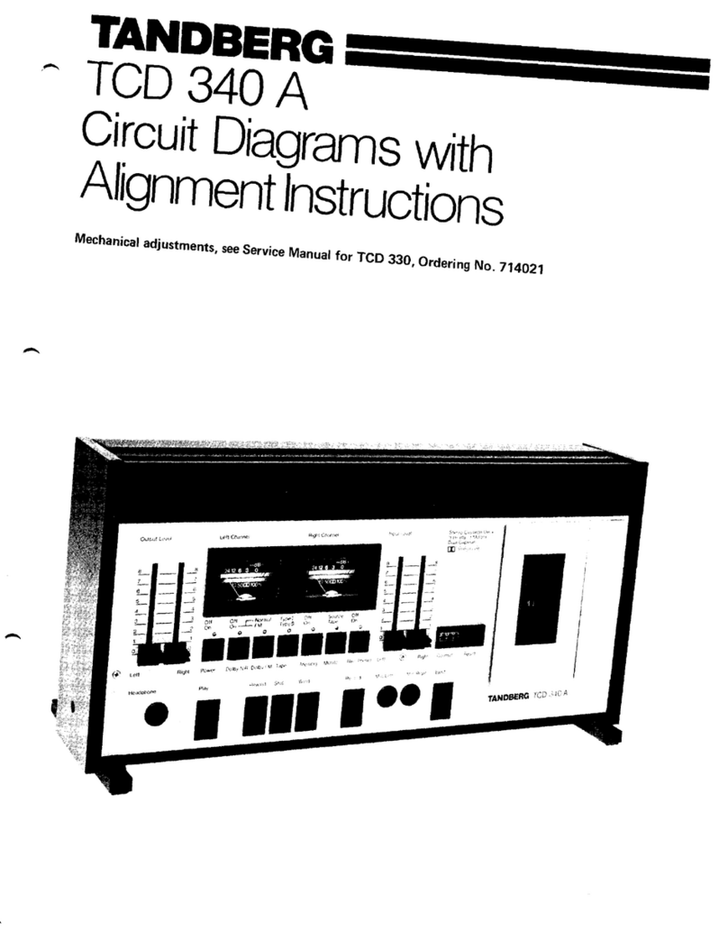
TANDBERG TCD 42OA User manual

TANDBERG'
TCD
42OA
CircuitDiagrams
with
AlignmentInstructions
n
TANDBERG'-The
European
Alternative
Electrical
checksand
adjustments
General
- 0 dB level is defined as:
0.775 V in the RADIO socket, using Ty'pe I or II
tapes.
1.2 V in the RADIO socket usingMetal tape.
1.5 V in the OUTPUT socketsusingType I or II
tapes.
2.3 V in the OUTPUT socketsusing Metal tape.
- Before adjusting, the tape path must be cleaned
and demagnetized.It is necessary
that the tape
path is correctly adjusted.
- Carry out the adjustments in the order described
because the adjustments affect each other.
- Remove the basepanel.
- When adjusting the Bias-traps
and the Bias-pre-
adjustment, the top panel must be removed.
Equipment required
- 2 millivoltmeters
- Audio signal
generator
- Frequency counter
- Distortion meter
- Wow and flutter meter
- Tandberg test cassettes:
- No. 21 (Speedcheck, 1000 Hz)
- No. 22 (Wow and flutter check, 3150 Hz)
- No. 23 (Azimuth adj. playb. head, 6300 Hz)
- No. 24 (Playback level adj., 1000 Hz)
- Measuringcassettes:
- Maxell UD XL I (Type I)
- Maxell UD XL II (Type II)
- Fuji Metal or TDK Metal MA (Metal)
Before adjusting, set buttons to:
- MPX-FILTER (situated at the back of the deck)
to OFF.
- Dolby NR.* to Off.
- Output Lcvel
controls
* The words "Dolby" isregistreredtrademarh of
Dolby Laboratories
Inc., US.Nfi stands
for
Noise
Reduction.
Before
adjusting,fold out page
5.
Oscillator
The oscillator
frequency
is between
80 and 100
kHz. The voltage
measured
on the erasehead
should
be
between6 and8volts
with TypeII or
Metal
cassettes.
Biastraps
- Remove the top panel.
- Nleasurewith a millivoltmeter on C107 and
C207 and adjust L101 and L201 to minimum
reading on the millivoltmeter.
Record/Playback head - azimuth
- Insert a Tandberg test cassette
No. 23 or a
standard azimuth cassette.
- Set the Monitor button to Taoe and connect a
millivoltmeter to eachchannel of the OTITPUT
sockets.
- Pressthe Play button. Adjust the playback
azimuth screw shown in the figure to obtain
maximum reading on eachchannel.
to maximum.
Playback
level
- Insert
Tandberg
test
cassette
No. 24 (Playback
level
adjustment
1000Hz).
- Adjust with the PLAYBACK LEVEL ADJ.
R317/R417
to 1.5V on the
OUTPUTsockets.
(In the RADIO socket,adjustto 775 mV.)
- If you useaDolby level
cassette,
adjust
to 1.2V
on the OUTPUT sockets
(0.615mV in the
RADIO socket).
Bias
(pre-adjustment)
- Set
theTCD 420Ato record,Metal
tape
loaded.
- Adjust with R21031IJ.2203
(Bias
Adjustment
Metal)
to approximately
8 - 9 mV measured
on
TPl andTP2 (on the Osc.
board),seefigure.

NOTE!
AdjustingtheTCD420A,usingthe RADlo-socket.
Overall frequency response with Metal tape
SettheTCD 420A to recording.
Adjust the gene-
rator to - 30 dB (= 25 mV on the millivoltmeters)
and record a40OHz, a 10 kHz, and a 15 kHz signal
at this level.
- Rewind and play back.
- Usethe 400 Hz signalas
a referenceand check
on both channelsthat the 10 kHz and 15 kHz
signals
arewithin the following tolerance:
r3dB.
If outside
thetolerance
adjust
R2103/R2203
BIAS
|DJ. M!,TAL. Then makea new recording,
play
backand
checkonce
more.
- If you cannot adjustto correctresponse
with
\?1991R2203, BIAS ADJ. METAL, thenadjust
R501/R601,
TREBLEADJ.METAL.
- Make
anewrecording,
playback
andcheck
once
more.
- Thencheckthe frequency
response
t 3 dB,30 -
18000
Hz.
- Whenthe frequency
response
is correct,
check
theresponse
with theDolby NR. circuit "On".
Recording Level - Metal tape
Connect anaudio-generator
and two millivoltmeters
to the RADIO-socket. Set the TCD 420A to
Record, use Metal tape. Adjust the generator to
400 Hz (= 450 mV on the millivoltmeters).
- Start recording.
- Rewind and play back (Output Level controls to
maximum).
- The millivoltmeters should now read approxi-
mately 450 mV (- 2 to 0 dB).
If outside the tolerance, make a new recording
while adjusting R105/R205, REC. LEVEL METAL
asrequired. Then play back and check once more.
Distortion - Metaltape
- Set
theTCD 420Ato recording.
- Generator
to 1000Hz (= 775mV on the
milli-
voltmeters).
- Rewindand
playback.
- Check
that thedistortionis( 3%.
- If outsidethe tolerance,
adjustR2103/R2203,
BIAS ADJ. METAL.
- Make
anewrecording,
playbackandcheck
once
more.
- Then check that the frequencyresponse
is
within thetolerance.
Signal/noise- Metaltape
Thesignal/noise
ratiosat 3To
distortion
should
be
at least
asgoodasspecified.Measure
with the
Dolby NR. circuit "On".
IECA-curve 68 dB
IEC Linear
RMS 56 dB
Program
meters
- Metaltape
- SettheTCD 420A to Record.
- Record a 400 Hz signalfrom the generator
(=11.2V on the millivoltmeters)
andadjust
the
program
meters
to 0 dB deflection
on theMetal
ry3l9_11th
Rl35/R235, METER LEVEL ADJ.
RECORD.
^
.*\ /
Adiustments
for typeI taPe
Recording Level
Adjustment
fortype
ll tape
Recording Level
lf outsiderhe tolerance
(- 2 to 0 dB), adjust { gutsidethe tolerance,
- 2 to 0 dB, adjust
R529/R629,
REC.LEVEL I. Donot touctr
Rl05/ R104/R204,
REC.LEVEL II.
R205' REC' LEVEL METAL' - Make
anewrecording,
playbackand
check
once
- Make
anewrecording,
playback
and
check
once more.
more.
- Usethe same
level as
for Metal tape (= 450 V on - Use the same
level as
for Metal tape (= 450 mV
the millivoltmeter). on the millivoltmeters).
- Record, rewind and play back. - Record, rewind and play back.
Overall frequency response Overallfreqeuncyresponse
Usethe same
levelas
for Metaltape
(= 25mV on
- Usethe same
level asfor Metal tape (= 25 mY the millivoltmeters).
on the millivoltmeters). If outsidethetolerance.
t 3 dB.
30- 18000
Hz,
If outside
thetolerance,
t 3dB,
30- 18000
Hz, adjust
R21021R2202,
BIASADJ.
II.
adjust
R2101/R2201,
BIAS
ADJ.
I. - Then check the frequency response
with the
- Then check
the frequency
response
with the Dolby NR. circuit "On".
Dolby NR. circuit "On". Distortion
Distortion - Record 1000Hz at 0 dB (= 77b mV on the
- Record
1000
Hz at 0 dB (= 775
mV on the millivoltmeters)'
millivoltmeters). - Rewindand
playback.
- Rewind
and
playback. - Check
that the distortion
is( 2%.
- Checkthat thedistortionis42%. If outside
thetolerance,
adjust
R104/R204,REC.
If outside
thetolerance,
adjust
R529/R629,REC. LEVEL II and R2102/R2202 BIAS ADJ' II.
LEVEL I and
R21021F.2202,
BIAS ADJ. I. - Then check the frequencyresponse
and the
- Then check the frequencyresponseand the distortiononcemore.
distortiononce
more.
Speed
check
PlaybackTandberg
testcassette
No. 21 (Speed
check 1000Hz) andmeasure
with a frequency
counter.on
the
output:t 1%
(990
- 1010
onthe
counter).
If necessary,adjust
to correctspeedwith R208'
SPEED
ADJ. on theMotor controlboard.
I
I
I
[ ,-"
il^
t
c{5?
t:
'E
?
T
3341
r I
33LJ
$2m
lfl
33?
lil
r19
F*fl
"r
b.l T
l][l
rf 1
llr
lra
lrH
-..1.
..
.
Baataaaa
cgir
,,
T
TMIC./LINE,
PLAYBACK'
AND
OUTPUT
AMP'
a 6lnE
FC,iii-ffi.+
#fi
ffi frfr
e ffirjf iil]L.l
url
L.l
uuLi
'
ffil;."'4-'*{ -ffi .qffi @*-; g
.',g4
oo4qo,,3_ 11 * +fl;:,;rr- i'i *- 1--;trroz
:ffi=-:i'
'1ffiH<fr:.ryIu5'"'
mii?
il ;g: .*-ffi "r^ -ffi Y;5ffi; T';
"i]:
.it
- ,'i'*i'#-i,:*-H$ffi$s:
- ?
#l
.l I
r or@-r
KF
J'iliBJ-S
tr-H-_:. J +''
rc'$.H
HSQ'1fl
"
#ffe
It' ,"',*FA $1EE-S"'#l-4r:#;.Ft
ftffi;Q"'5 rc'oo
fsE&*H+ ,
gJ glt9 .,.0, . dF?9 Oto.
.r,o,]
,-#
'; ""**HA';,*g
'El.El<.,.
ot*tq#ffiS*
btl-Er*'ffiffi
.--,"
.,*,,''
T r4rp*r'.'"t
gffiBj sls,,u
.f,+:G$%.P .**
lirrrtalaaf'l
MAIN
./^
I Jr
Inrc.r.rv.nlxr.I
rffi
"r.. rN
r t " --TlrT
#Jfrh lllj
&ffi}:'i::::::
MOTOR
SIGNALAMP.AND
DOLBY/TAPE
SELECTORS
.'.*r
flfuff;t,fis.1.ffjh3H
"f'"f'
tlr.l [rJ tlgJ tl'.l -L r
808 811 8it 8r9 -T T
+-@F< o{E@< ' '
801
!;N
*{m-en-r bll
r,*'l-.l
l" 'l
fr r rl
'L.,,.
, 'l
LcJ
:ffi I'3&,
*lfacaoe J lrl
rF-€IEFr _l!J
.-1
F-"-"rou [! loro,
e{EEts Lil
OSCILLATOR
c711 ,l
# '1h,:Tl:, iid: 4fit .l:.
*gT :l,,.,li
*g- --*- -:{i*-
--@11-. --ffi-- :l l: *-tlry- .-]F- ?...r
i6'T- -?,h ,:l-l:,u
>-@ll-- ,-lFlg- .fffi'..
''.G. ;;;,-; ;,r *rre3o'€-rPs
----s,,
el
| | | I I I I
el,:ffi":ffi
DOLBY
P60
o6d
il
FIFI
TT
lt
.e.'t$
{ dEl
?|
ir
.{frmh
t -=J
Jr.
&,4
r. -,Ei[
Ir
.ffia
L-J
t:
#
FJ
T
Ia'
I
tFt
T
'a
f,
r@h
Lrd
.t'tl.
#
BIAS
to
6!
lo
I
@A'
@^2
'f,,;fb
++#'Lr#,,i
HFffi;;$*hAA&$rH?9H
FB
*:d]H
Y
ffiI1'1
ry"g
tg'$*e
-t azoo6 !Eor' izo
MOTOR
CONTROL,CAPSTAN
)
Ito I
6C. I
fll
$l
rl
kri I
ffil
$riI
__l
Trimmingpots. on theMain board,seen
from thesolder
side
-- !*fi { )cms I
il
?"ro,m"fu,a
.lt
lm c6o? +
,__. El:_g
T-lRe3:1 { l*r.*,
033?51
lru;:+- | I reor
\ /ti i=i
nI [,,}Jr] I'------I ll I
lll lnur!_Jl I I ll I
-ut I tlt I
ll c8o6T______]l I tJtJ
4803r I R822--
Oscillator measurement points, scen from the component side
BIAS
Azimuth screw on the recordfplaybach head
r
5E
=o
N3
I
cso
T,,
I
Icso7
T'"'
o501
8C517B
o503 | o50a
ac5178| BC5a78
MOTORSIGNAL
AMP
DOLBY/TAPE
SELECTORS
63118
SWITCHES
SHOWN
FROM
SOLDER
SIDE,
AND IN UNOPERATED
POSITION.
c511
OrotI
!
METAL J-
L
I oscrt-uron ffin4
tl
r+
IN
LMETAL J
' -",n*- -B1 MOTOR
CO-t-O-GES 1-4) - - I
2001
. NOTES:
T.UNLESS
OTHERWISE
SPECIEFIEO
RESISTANCEtN
OHMS.
2, azooz,
nzoosANoR2or aRE r./. METALFILMREsrsToRs
3. czool.
o.rp 5. PoLYKARBoNAT.
4. nzooe-rxrcx
FILMvARIABLEREsrsroR.
! ooLeYG3o2o L-ANDR-cH. !
IN6r48
!
I
c710
|
3lt3
i,"
c117) j
r"
r"'
torT -T- -Euor
l"l-l
ltl
J LI-,
leH
eHtl
II
II IIIRI+
ffi
-Hl
l,+-G
lH'"'"
*H"
*}
I'"
A
t-
L
DOLBY 63020
L-CH.
e
l----effr---l
BIAS
RECORD RECOROLEVEL
RIGHT
l
I
I eause
l--
PLAYBACK-AND I Msr
sLrDE
OUTPUT
AMP I
OUTPUT
LE
PINCH ROLLER
SOLENOID
lsl :
63151 :i-q h
MIC./LINE- ffiJ
I
o (nEwtNo
$ |sroe
5{ wtND
5 |plav
Hl-necono
H
,l
.l
li
n
ll
r-J
ERASEHEAD
-L
i:13!q-
tl-l-391-J-
#i+c#
"f
F-irr
t--..1
u
301' '
io:"i-
3o!_l_-i
sodl
3051--t
3091_-t
301]-J
308r I
3091_-l
31q-!-l
311_l_-t
31?_L-.l
313_l-!
3r!_l_-,1
31:-lJ
316r I
3lz_L-l
3r9-l--l
t--.]
3191_-.1
329_.1_-i
32!_t_-,1
323.1_J
323_l_-l
32!_!_l
f ---tl-ljn-- I
-L
^ r,lr rg19
i i r>, rBlB
Qlr-stt 63121
OSCILLATOR
'ts
IRACK2t3)
RIGHT
CH, -L
- ^ l-rr 1806
( * f-: rnl--r eoe
- Y-.I.)--Lqo?
DFI
_t_
,^^r,jr r8t6
( X Llr/Ylt-rgls
t:r I
-t-
I
["'
,f-- I
--I
J
.--iu
.l
ur
I
oB01
II
L______-J I
LU
t
H
as2z !9?
!--!
503r r
'526 |
'6i.- :99-
E r+*i-
' 63ttg -^-E
507r I
M0T0RSIGNAL
AMP soEE
To
osc. DOLBV/TAPESELECTORS 50!-r-1
c.^ Tl
slq_i:
s1L_t-.l
s1:__l..l
511_!-,1
s14_!-l
s1!_l_-,1
512_L-.,1
s1qJ_-l
L--l
519r I
520r I
521r ,
SrD
52!_l_-i
s2!)_J
ourPu
t€vr
RIGHI
t-
L
DOLBY63020
R-CH.
-l I
o6
I
rMOTORCONTROL
CAPSTAN 63513
REWINO WINO
R2r0 -'l R2l2 ACTITINEAR
AMP
irFrFiFrFrFrFrFrFr
I
11111111-tL
J
0t06
8C51?
Qlll
BC51t
l-;-*
AMP
I z2jy
!
RECORDAMP
R-CH.
o202
tc557A
c103
10! ozlL
BCS17
63112 MAIN
BOARD
-1
'i'* W:
tC228 L BC51?B
I
I
I
I
i
I
I
I
I
i
I
I
_.i
I
I
I
L
I
I
I
I
I
I
_____________l
oNd A_-d
oFF
'l FM-MPX
F--
ECB
Att voltoges or. meosured with V.T.VM.
with inpul impedonce min.l0Mohhs.
Alt DC volloges neosured without signsl.
@ n"no,", signol vottoges lloooHz)
16V Oenot€s 0C voltoges.
RI
OIJIPUT LEVEL u'-l-\.n..r
/ \ Bc54e
\l___-9J Bcs57
TRANSISTORS
SEEN
FROM UNOERNEATH
B0 175
BD176
RIOHI
- -fYYYYYYYYYT
-1
l-t-l-t-t-t-t-t-t - |
' F'P'P'P'P'P'F
P'P' I
-lI
I:Pr
I
METER AMP.
o110
4c517
METERAME
sro2
3l5mAT ;\--
f._-230v soxz
;]'--
;\-ltov ooHz
NEAR
i
tP. i
I
I
l0l I
'$ll
-1-t I
o111
4c547
I
i c221
| 2e2
c122
-{F
2tz
l00p
I i
'8 li
oo
ll
--tJ
I
c126
T zpz
J-
LEVEL
IND,L
Tt, i
)209
IH
TJ
6
t!
c226 lc227l
rRD
c110
|
*T
I
I
I TL7, El"
I.f
(t.i) o""0,.. s,snol voltoses (loooHz)
1mV Denotes 0C vottogls
PLAYBACK AMP
PLAYBACKAMP
12V i
I
MIC./LINEAMP R-CH,
31S Ca05
L1t 2n2
63r51 Mtc./L|NE-,
I
PLAYBACK AMP
L'
F
lL
f
o
63151 MIC./LINE-,
PLAYBACK-,
AND OUTPUT
AMP
SWITCHES
SHOWN
FROM
SOLDER
SIDE,
ANDIN UNOPERATED
POSITION.
AI
I
I
I
+
;-?
ART/STOP
tcu|r
1727
-G
-
80 Part
No.714136
Printed
inNorway
by Reclamo
A/S
GrTandbers
A/S,
1980
l:I Tandberg
A/S, Post
OfficeBox 55, Bogerud,N-Oslo
6, Norway

Other TANDBERG Cassette Player manuals

TANDBERG 10X User manual

TANDBERG

TANDBERG 10X User manual

TANDBERG 6000X Series User manual

TANDBERG

TANDBERG 6000X Series User manual

TANDBERG TCD 910 User manual

TANDBERG

TANDBERG TCD 910 User manual

TANDBERG EDUCATIONAL TCR 222 User manual

TANDBERG

TANDBERG EDUCATIONAL TCR 222 User manual

TANDBERG TCD 340 A User manual

TANDBERG

TANDBERG TCD 340 A User manual

TANDBERG TCD 310 User manual

TANDBERG

TANDBERG TCD 310 User manual

TANDBERG TCD 340A User manual

TANDBERG

TANDBERG TCD 340A User manual

TANDBERG TCD 310 User manual

TANDBERG

TANDBERG TCD 310 User manual

TANDBERG TCD 3034 User manual

TANDBERG

TANDBERG TCD 3034 User manual

TANDBERG TCD-3014A User manual

TANDBERG

TANDBERG TCD-3014A User manual

Popular Cassette Player manuals by other brands

Sony Walkman WM-EX526 operating instructions

Sony

Sony Walkman WM-EX526 operating instructions

Technics RS-M226 Service manual

Technics

Technics RS-M226 Service manual

Hyundai H-1416 instruction manual

Hyundai

Hyundai H-1416 instruction manual

Sony TC-KE400S operating instructions

Sony

Sony TC-KE400S operating instructions

Pioneer CT-W830R operating instructions

Pioneer

Pioneer CT-W830R operating instructions

Aiwa HS-PS007 Service manual

Aiwa

Aiwa HS-PS007 Service manual

Philips AQ6411/00 user manual

Philips

Philips AQ6411/00 user manual

Sony Walkman WM-EX9 Service manual

Sony

Sony Walkman WM-EX9 Service manual

Sony Sports Walkman WM-FS473 operating instructions

Sony

Sony Sports Walkman WM-FS473 operating instructions

Sony TC-WE805S instruction & operation manual

Sony

Sony TC-WE805S instruction & operation manual

Panasonic RXFT530 - RADIO/DUAL CASS-LOW operating instructions

Panasonic

Panasonic RXFT530 - RADIO/DUAL CASS-LOW operating instructions

Rotel RD-500 owner's manual

Rotel

Rotel RD-500 owner's manual

Sharp QT-CD7L Bedienungsanleitung

Sharp

Sharp QT-CD7L Bedienungsanleitung

Aiwa TP-VS480 operating instructions

Aiwa

Aiwa TP-VS480 operating instructions

Sanyo MCD-S920F Service manual

Sanyo

Sanyo MCD-S920F Service manual

ELECTRO BRAND 2034 user guide

ELECTRO BRAND

ELECTRO BRAND 2034 user guide

Sony CFD-G555CP Service manual

Sony

Sony CFD-G555CP Service manual

Aiwa HS-RX128 operating instructions

Aiwa

Aiwa HS-RX128 operating instructions

manuals.online logo
manuals.online logoBrands
  • About & Mission
  • Contact us
  • Privacy Policy
  • Terms and Conditions

Copyright 2025 Manuals.Online. All Rights Reserved.