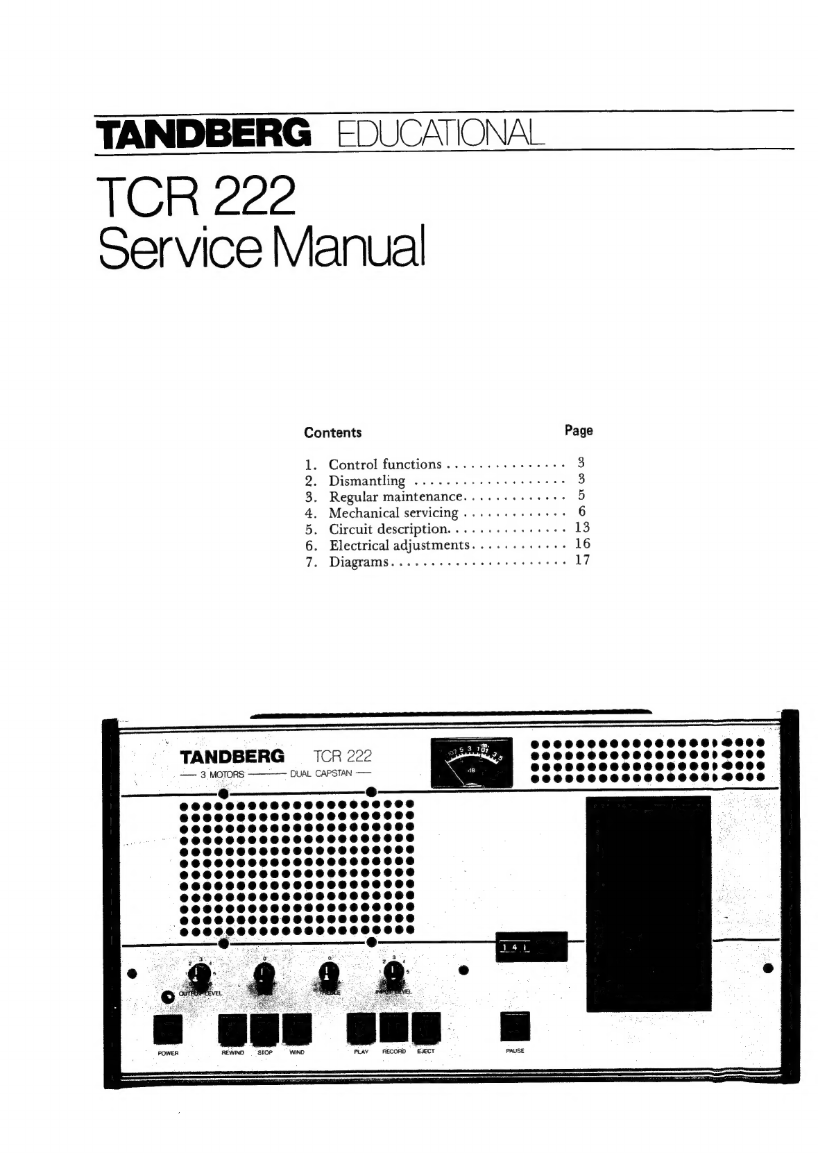
TANDBERG EDUCATIONAL TCR 222 User manual

TANDBERG
§DUCATIONAL
TCR
222
Service
Manual
Contents
Page
1.
Control
functions
..........++++.
3
2.
Dismantling
........--..
eee
sees
3
3.
Regular
maintenance.......+-+.++>
5
4.
Mechanical
servicing
.....--.+++--
6
5.
Circuit
description.
.......--.+.++-
13
6.
Electrical
adjustments..........--
16
7.
Diagrams.
......-
ese eee
cere
eee
17
TANDBERG
=
CR
222
a
——
3
MOTORS
DUAL
CAPSTAN
——
REWIND
STOP
WIND
PLAY
RECORD
EJECT

General
specification:
Adjusted
for
Tandberg
Tape
or
any
other
high
equal
quality
tape.
Can
be
used
in
a
vertical
position
or
mounted
on
the
wall.
Dimensions:
Breadth
16
7/8”
(43.5
cm),
height
4
1/8”
(10.5
23
cm).
Weight:
13.5
lb
(6
kg).
Technical
specification:
Power
requirements:
230
V,
50
Hz.
Power
consumption:
60
watts
max.
Tape
speed:
1
7/8
ips
(4.75
cm/s).
Speed
tolerance
with
nominal
mains
voltage
and
normal
operating
temperature:
+
1%.
Wow
and
flutter,
max:
DIN
45500
peak
value
better
than
0.2%.
Frequency
response,
Tandberg
XD
tape:
40
—
14
000
Hz
(DIN
45500).
Signal/tape
noise
ratio,
DIN
45500:
Better
than
58
dB
(Gerduschspannung),
A-curve
and
better
than
55
dB
(Fremd-
spannung).
Distortion,
max.:
From
tape
at
0
dB
record
level:
3%.
Inputs:
MIC:
Suitable
for
dynamic
microphone
with
impedance
less
than
700
ohms.
Sensitivity
0.1
mV
to
17
mV
at
200
ohms.
RADIO:
Input
impedance
47
k
ohms.
Sensitivity
10
mV
to2
V.
PHONO:
Input
impedance
3
M
ohms.
Sensitivity
45
mV
to
5.0
V.
Outputs:
RADIO:
Output
voltage
0.8
V.
EXT.
SPEAKER
4
-
8
ohms.
Output
power
12
watts
in
4
ohms.
Tone
controls:
Treble
control:
-8
dB
to
+
8
dB
at
10
000
Hz.
Bass
control:
-8
dB
to
+
8
dB
at
100
Hz.
Transistors:
39.
Motors:
1
hysteresis
synchronous
motor
115
V,
50
Hz.
2
DC
winding
motors,
14
V.
IN
ANY
COMMUNICATION
PERTAINING
TO
THE
EQUIPMENT,
PLEASE
SPECIFY
TYPE
NUMBER
AND
SERIAL
NUMBER

1.
CONTROL
FUNCTIONS
OUTPUT
LEVEL.
BASS
—
TREBLE.
INPUT
LEVEL.
Adjust
until
the
Program
meter.
Volume
control
for
Tone
controls.
program
meter
needle
hits
the
edge
Shows
the
level
of
speaker(s).
Use
for
of
the
red
zone.
Use
for
recording
the
input
signal.
playback
and
when
and
when
the
TCR
222
is
used
as
TCR
222
is
used
as
an
amplifier
for
e.g.
a
microphone
an
amplifier.
program.
On/off
indicator
lamp.
POWER.
On/off
button.
Counter
with
zero-button.
REWIND.
PAUSE.
For
short
Fast
backward
pauses
during
record
tape
winding.
or
playback.
STOP.
Stops
the
tape
WIND.
PLAY.
Press
to
playback
a
cassette.
RECORD.
Press
torecord
ona
EJECT.
Opens
the
cassette
Fast
forward
Control
speaker
volume
with
OUT-
cassette.
Adjust
until
the
program
compartment.
tape
winding.
PUT
LEVEL
knob.
Set
the
INPUT
meter
needle
hits
the
edge
of
the
NB!
The
STOP
button
must
be
de-
LEVEL
knob
to
0
to
avoid
input
red
zone.
pressed
before
the
EJECT
button
programs
mixing
with
the
playback
NB! The
PAUSE
button
must
be
can
be
used.
Underneath
the
re-
program.
depressed
before
the
RECORD
corder
there
is
also
a
manual
cassette
button
can
be
used.
eject
lever
that
can
be
used
when
the
recorder
is
not
connected
to
the
power
supply.
2.
DISMANTLING
2.1
REMOVAL
OF
TOP
PANEL
1.
Release
the
cassette
compartment
by
pressing
the
EJECT
button,
or
operate
the
manual
cas-
sette
release
lever
as
shown
in
fig.
2.1,
2.
Remove
the
plastic
lid
from
the
cassette
com-
partment
by
pulling
it
upwards.
Push
the
compartment
down
to
closed
posi-
tion.
LOOK
OK
AGEL
HOKOEROHSY
3.
Remove
3
screws
on
the
top
panel,
and
3
YRMORERG
0s
TrereRreee
este
NT
eEe:
DQAPHAHOKAOKATILOL
KOOKS
PHIL
POR
OGAP
EL
HOKGOROH
Pen
screws
at
the
top
of
the
rear
panel
according
SPE
P
eR
PRET
to
fig.
2.2
SonezonoeRoreanesenoe
yy
awe
BRLE
SOK
AO
RPK
LYON
OKO
SHUOXAORDHSHOLGOKOKAOA
POXOKR
SYS
LSD
KOKRAGALH
SEY
KAGELESKOKAOAGHA
WOR
IO
PHLWOKEOAPK
AYER
AOKOKA
OX
SOKOK
AVE
LEO KOK
AOKESY
ROKRAGSLHSKOKAGKALS
VOR,
VALS
OHSK
ROK
SHAVES
HOKE
SLELHOKOSALELHOKACAIA
2.
4.
Remove
the
top
panel
by
lifting
the
right
edge
first.
IMPORTANT!
Note
the
position
of
the
colored
wires
before
disconnecting
the
loudspeaker
and
the
mains
indicator
LED.
Fig.
2.2
Removal
of
top
panel

2.2
REMOVAL
OF
SWITCH
ASSEMBLY/
AMPLIFIER
2
BOARD
The
Amplifier
2
Board
is
soldered
onto
the
switch
assembly,
and
the
switch
assembly
is
mounted
on
a
bracket
which
is
fastened
to
the
front
panel
with
2
screws.
To
remove
the
switch
assembly/
Amplifier
2
Board,
see
figures
2.3
and
2.4.
Proceed
as
follows:
Remove
Amplifier
1
Board.
Remove
3
screws
marked
Al-A3.
Remove
bracket
B.
Remove
the
PAUSE
switch
button
C.
Remove
the
switch
assembly.
2.3
MOUNTING
THE
SWITCH
ASSEMBLY/
AMPLIFIER
2
BOARD
Berfore
mounting
the
switch
assembly,
make
sure
that
the
transistor
leads
of
Q
207
is
not
shor-
ted.
Q
207
is
positioned
at
the
right
side
edge
of
the
board.
See
fig.
2.4
and
proceed
as
follows:
1.
Re-install
the
assembly
by
plugging
the
con-
nectors
at
the
bottom
of
the
board.
Fasten
assembly
with
screws
Al
and
A2.
2.
Place
the
lugs
of
lever
D
into
slots
E.
3.
Re-install
the
PAUSE
switch
button
C.
4.
Operate
the
PAUSE
switch
button
several
times
to
make
sure
that
nylon
slide
F
moves
far
enough
to
allow
the
RECORD
switch
to
be
operated.
5.
Re-install
bracket
B
and
fasten
with
screw
A3.
6.
Re-install
Amplifier
1
Board.
AMPLIFIER
1
BOARD
AMPLIFIER
2
BOARD
Fig.
2.3
Position
of
printed
circuit
boards
2.4
SERVICING
THE
AMPLIFIER
1
AND
AMPLIFIER
2
BOARDS
A
special
service
kit
consisting
of
two
extender
boards
is
available,
to
simplify
the
servicing
of
Amplifier
1
and
Amplifier
2
Boards.
The
extender
boards
can
be
ordered
under
Part
No.
994
178.
m
Oo
co)
wo
Fig.
2.4
Switch
assembly

3.
REGULAR
MAINTENANCE
3.1
CLEANING
The
parts
of
the
cassette
deck
that
are
in
contact
with
the
tape
surface
should
be
cleaned
regularly,
otherwise
the
sound
quality
will
be
greatly
reduced.
Cleaning
of
capstans
and
pinch
rollers
is
particularly
important
to
avoid
wow
and
flutter.
If
the
cassette
deck
is
used
every
day,
cleaning
should
be
performed
at
least.once
a
month.
The
cleaning
can
be
done
with
cotton
wool
or
a
piece
of
flannel
wrapped
around
a
small
stick
and
moistened
with
pure
alcohol
or
methylated
spirit.
A
kit
intended
for
this
purpose,
”
Tandberg
Profes-
sional
Tape
Head
Cleaner”,
is
available
under
part
no.
352
156.
NOTE!
Do
not
use
solvents,
such
as
acetone
or
trichlor-
ethylene,
as
these
may
damage
the
heads.
How
to
clean
1.
Release
the
cassette
compartment
by
pressing
the
EJECT
button
or
operate
the
manual
cas-
sette
release
lever.
Remove
the
plastic
lid
from
the
cassette
com-
partment
by
pulling
it
upwards.
Push
the
cassette
compartment
down
to
closed
position.
9.
Clean
the
record/playback
head
(A),
erase
head
(B),
tape
guide
(C),
capstans
(D)
and
pinch
rollers
(E).
Do
not
use
too
much
cleaning
liquid
on
the
pinch
rollers,
and
dry
them
afterwards.
DO
NOT
USE
ANY
SHARP
OBJECTS
WHEN
CLEANING.
DO
NOT
TOUCH
THE
ADJUST-
MENT
SCREWS.
3.
Check
the
surrounding
area
for
dust
and
de-
posits
from
the
tape.
Clean
if
required.
Cleaning
should
be
performed
both
before
and
after
adjustments.
Fig.
3.1
Parts
to
be
cleaned
3.2
DEGAUSSING
A
marked
increase
in
background
noise
from
the
tape
may
indicate
that
the
heads
or
other
parts
in
the
tape
path
should
have
the
residual
magnetism
removed
(degaussing).
If
required,
degaussing
should
be
carried
out
as
follows.
Switch
off
the
deck.
Remove
the
cassette
from
the
deck.
Remove
the
plastic
cassette
compartment
lid
and
move
the
de-
gausser
slowly
past
each
one
of
the
metal
parts
normally
in
contact
with
the
tape.
Take
great
care
not
to
let
the
degausser
touch
the
heads
or
metal
parts
in
the
tape
path.
Do
not
switch
off
the
de-
gausser
until
it
is
at
least
3
ft
away
from
the
recorder.
Degaussing
should
be
performed
both
before
and
after
adjustments.
3.3
LUBRICATION
The
capstan
motor
and
the
reel
motors
rnay
require
lubrication
from
time
to
time.
T
he
interval
between
each
lubrication
should.
be
at
least
3000
hours
of
operation.
Use
the
following
types
of
oil:
Capstan
motor:
ANDEROL
465
fromTenneco
Chemicals,
USA.,
or
oil
supplied
by
Tincherg,
under
part
no.
713
368.
Reel
motors:
NUTO
H36
(also
called
SPENESSO
34)
from
Esso.
NOTE!
Use
only
one
drop
of
oil
for
each
moor.

4.
MECHANICAL
SERVICING
4.1
MICROSWITCH
MS
1
Pinch
rollers
released:
Check
that
there
is
a
gap
of
about
1
mm
between
the
connecting
arm
and
the
middle
leaf
of
the
switch.
See
fig.
4.1.
Pinch
rollers
operated:
Check
that
the
left
and
the
middle
leaf
are
pressed
together.
4.2
TAPE
PATH
ADJUSTMENTS
If
parts
in
the
tape
path
have
to
be
replaced,
a
more
or
less
complete
adjustment
procedure
should
be
carried
out.
This
adjustment
procedure
requires
the
use
of
special
tools,
and
should
be
carried
out
by
a
Tandberg
representative.
If
the
tape
path
only
needs
minor
adjustments,
only
visual
inspection
and
one
single
electric
measurement
is
ordinarily
needed.
Then
see
4.2.1,
"Outline
of
the
adjustment
proce-
dure’.
IMPORTANT!
DO
NOT
USE
MAGNETIC
TOOLS
WHEN
ADJUSTING
PARTS
IN
THE
TAPE
PATH!
4.2.1
Outline
of
the
adjustment
procedure
The
following
equipment
is
needed:
—
Tandberg
Test
Tape
No.
23
(Azimuth)
—
Tandberg
Test
Tape
No.
29
(Open
cassette)
Instead
of
the
Tandberg
Test
Tape
No.
29,
one
may
use
an
ordinary
high
quality
cassette
which
has
been
cut
open,
so
that
the
tape
is
visible.
See
fig.
4.2.
Insert
Tandberg
Test
Tape
No.
29.
Check
that
the
tape
does
not
climb”
on
the
capstans
and
is
not
bent
or
folded
at
the
tape
guides.
Also
check
that
the
tape
does
not
”bulge”
at
the
heads
(”*bulging”
indicates
wrong
azimuth
adjustment
of
the
heads).
When
viewed
from
above
the
tape
should
be
seen
as
an
almost
invisible
line.
Also
check
that
the
top
of
the
erase
head
(Japan-
ese
heads
only)
is
flush
with
the
top
edge
of
the
tape.
The
erase
head
should
not
be
visible
above
the
tape.
If
the
erase
head
is
made
by
Tandberg,
and
marked
with
a
Tandberg
label,
the
top
of
the
erase
head
should
be
0,82
mm
above
the
top
edge
of
the
tape.
See
fig.
4.3.
LG:
|
coach
ie
lever
>
Bracket
ao
*,
i
gue
arm
zi
Pa
P|
Fig.
4.1
Pinch
rollers
released
Fig.
4.2
Tandberg
Test
Tape
No.
29
Open
cassette
Erase
head
made
by
Tandberg
Japanese
made
erase
head
Fig.
4.3
Adjusting
the
height
of
the
erase
head

If
erratic
tape
motion
is
observed,
try
to
eliminate
it
by
turning
the
adjustment
screws
for
heads
or
pinch
rollers.
Insert
a
Tandberg
test
tape
No.
23
and
adjust
with
the
screw
AZ
on
the
record/playback
head
to
maximum
output
signal
on
a
VIVM,
connected
to
the
RADIO
socket.
See
fig.
4.4.
4.2.2
Adjustment
procedure
The
following
equipment
is
needed:
—
Tandberg
Adjustment
Plate,
part
No.
713 537
—
Adjustment
Tool
No.
2,
part
No.
716
391
-
Adjustment
Tool
No.
3,
part
No.
716
406
—
Adjustment
Tool
No.
4,
part
No.
716
502
—
Tandberg
Test
Tape
No.
23
(Azimuth)
—
Tandberg
Test
Tape
No.
29
(Open
cassette)
Adjustment
Tool
No.
2
is
packed
with
the
adjustment
plate.
IMPORTANT!
Take
great
care
not
to
damage
the
head
fronts
when
using
the
tools
No.
2
and
3.
Ferrite
heads
are
easily
damaged.
DO
NOT
depress
the
PLAY-button
when
the
tools
are
in
use.
When
adjusting,
first
move
the
mounting
plate
with
the
pinch
rollers
and
the
heads
by
hand,
then
hold
the
mounting
plate
with
one
hand
and
move
the
tool
towards
the
head
with
the
other.
Be
sure
to
move
the
mounting
plate
strictly
horizon-
tally,
not
pressing
it
downwards
nor
lifting
it.
This
is
of
great
importance
to
the
result
of
the
ad-
justments.
4.2.2.1
Pinch
rollers
Height.
Insert
the
Tandberg
Adjustment
Plate
and
move
the
mounting
plate
inwards
until
the
pinch
rollers
almost
touch
the
capstans.
Holding
the
mounting
plate
in
position
with
one
hand,
place
Tool
No.
2
on
the
Adjustment
Plate
as
shown
in
fig.
4.8.
Adjust
with
the
screw
P
on
roller
1
so
that
the
tip
of
Tool
2
fits
into
the
tape
guide
of
the
roller.
Also
adjust
the
two
screws
H
if
neccesary.
Turn
both
screws
equal
amounts.
Also
turn
the
azimuth
screw
AZ
correspondingly
in
the
op-
posite
direction
to
keep
the
roller
roughly
in
correct
azimuth
position.
Parallelity.
Remove
pitch
roller
1
and
look
at
figures
4.6
and
4.8.1.
for
the
following
procedure:
Install
Tool
No.
4
as
shown
in
the
figure.
The
capstan
should
fit
into
the
gap
of
the
tool.
Put
a
miniature
bulb
down
into
the
sylindric
hole
of
the
tool
.
The
light
from
the
bulb
shines
through
the
gap
to
simp-
lify
the
adjustments.
Fig.
4.5
Height
Azimuth
Parallelity
Fig.
4.6
Parallelity
of pinch
roller
~,
wernt:
Ke
Fig.
4.7
Adjustment
screws
for
firtch
rollers
Fig.
4.8
Tandberg
Adjustment
Plate
with
Tool
No.
2
Fig.
4.8.1
B
Positioning
Tool
No.
4
90°
aa
&
CAPSTAN
PINCH
ROLLER
SHAFT
Ol
NO.
4

Move
the
mounting
plate
inwards.
Adjust
the
screws
H
to
minimize
the
gap
as
viewed
from
direction
A.
Observe
the
gap
from
direction
B
and
adjust
the
screw
AZ
so
that
the
capstan
is
perfectly
parallel
to
the
tool,
or
at
least
minimize
the
gap
as
far
as
possible.
By
adjusting
the
screws
H
and
AZ
several
times
the
capstan
should
be
perfectly
parallel
to
the
tool.
Adjust
pinch
roller
2
following
the
same
procedure.
Adjusting
height
and
parallelity
without
using
Tool
No.
4.
Insert
Tandberg
Test
Tape
No.
29,
the
open
cassette.
Move
the
mounting
plate
inwards.
Look
at
fig.
4.7
and
adjust
with
the
screw
P
on
roller
1
so
that
the
tape
fits
into
the
tape
guide
of
the
roller.
Also
adjust
the
two
screws
H
if
neccesary.
Turn
both
screws
equal
amounts.
Also
turn
the
azimuth
screw
correspondingly
in
the
opposite
direction
to
keep
the
roller
roughly
in
cor-
rect
azimuth
position.
Adjust
pinch
roller
2
to
corresponding
height.
This
adjust-
ment
is
not
critical.
See
figures
4.6
and
4.7,
and
adjust
with
the
screws
P,
so
that
both
rollers
are
in
parallel
with
the
capstans.
A
white
piece
of
paper
can
be
inserted
behind
the
pinch
rollers
and
the
capstans
to
make
in
easier
to
observe
the
gap
between
them.
See
fig.
4.6.
Check
that
the
tape
is
not
bent
or
folded
at
the
tape
guides,
or
clims
the
capstans..
If
neccesary,
adjust
the
screw
AZ.
Pinch
roller
operation.
Remove
the
Adjustment
Plate
or
the
cassette.
Move
the
mounting
plate
inwards.
Check
that
both
pinch
rollers
touch
the
capstans
at
exactly
the
same
time.
The
pinch
rollers
will
start
rotating
when
they
meet
the
capstans.
If
required,
adjust
the
eccentric
screw
shown
in
fig.
4.9.
4.2.2.2
Erase
head
Preadjustment
of
head
mounting
plate.
Adjust
with
the
screws
H
and
AZ
shown
in
fig.
4.12
so
that
the
head
moun-
ting
plate
is
parallel
to
the
underlying
mounting
plate.
The
gap
between
them
should
be
approx.
1
mm.
To
check
this
the
right
chassis
plate
must
be
removed.
Adjustment
of
erase
head
made
by
Tandberg.
Insert
the
Tandberg
Adjustment
Plate
and
move
the
mounting
plate
inwards.
Keep
the
mounting
plate
in
position
with
one
hand.
Place
Tool
No.
3
on
the
Adjustment
Plate
according
to
fig.
4.11.
See
also
fig.
4.12
and
adjust
the
screws
H
and
AZ
so
that
the
top
of
the
erase
head
is
flush
with
the
tool.
The
front
of
the
erase
head
should
be
parallel
to
the
front
of
the
tool.
Adjustment
of
Japanese
made
erase
head.
Replace
tool
No.3
with
Tool
No.
2
and
carry
out
the
adjustment
described
above.
Adjusting
the
erase
head
using
Tandberg
Test
Tape
No.
29.
In
this
case,
insert
the
cassette
and
move
the
mounting
plate
inwards.
If
the
erase
head
is
Japanese
made,
adjust
with
the
screws
H
and
AZ
as
shown
in
fig.
4.12,
so
that
the
top
of
the
erase
head
is
flush
with
the
top
edge
of
the
tape.
If
the
erase
head
is
made
by
Tandberg,
and
marked
with
a
Tandberg
label,
the
top
of
the
erase
head
should
be
0.82
mm
above
the
top
edge
of
the
tape.
See
fig.
4.3.
.
Eccentric
screw
Sf
oe
Fig.
4.9
Adjustment
screw
for
pinch
roller
operation
Head
mounting
plate
Mounting
plate
Fig.
4.11
Tandberg
Adjustment
Phte
with
Tool
No,
3.
Fig.
4.12
Adjustment
screws
for
the
erage
head

4.2.2.3
Record/
Playback
head
The
position
of
the
record/
playback
head
is
adjusted
by
turning
the
screws
on
the
head
bracket
shown
in
fig.
4.13.
Do
not
touch
the
adjustment
screws
on
the
head
mounting
plate,
as
it
isassummed
that
this
plate
has
already
been
cor-
rectly
adjusted
according
to
4.2.2.2
”Erase
head”’.
Height
and
parallelity.
Insert
the
Tandberg
Adjustment
Plate
and
move
the
mounting
plate
inwards.
Hold
the
moun-
ting
plate
in
position
while
placing
Tool
No.
2
as
shown
in
fig.
4.14.
See
also
fig.
4.13,
and
adjust
with
the
screws
H
and
P
so
that
the
tool
fits
into
the
tape
guide
on
the
head.
The
front
of
the
head
should
be
parallel
with
the
tip
front
of
the
tool.
Adjusting
height
and
parallelity
using
Tandberg
Test
Tape
No.
29.
After
having
inserted
the
cassette,
move
the
moun-
ting
plate
inwards.
See
fig.
4.13
and
adjust
with
the
screws
H
and
P
so
that
the
tape
fits
exactly
into
the
tape
guide
of
the
head.
The
front
of
the
head
should
be
parallel]
to
the
tape.
If
not
already
done,
insert
Tandberg
Test
Tape
No.
29,
the
open
cassette
shown
in
fig.
4.2.
Set
the
recorder
to
PLAY.
Check
that
the
tape
is
not
bent
nor
folded
at
the
tape
guides
and
does
not
bulge
at
the
heads.
Azimuth.
Insert
Tandberg
Test
Tape
No.
23
(6300
HZ).
Connect
a
VTVM
to
the
RADIO
socket
at
the
rear
panel.
Set
the
recorder
to
PLAY
and
adjust
with
the
screw
AZ
as
shown
in
fig.
4.13
to
maximum
output
reading
on
the
VTVM.
Finally,
check
the
height
and
parallelity
again.
Readjust
if
neccesary.
If
any
readjustment
is
made,
azimuth
must
also
be
checked.
4.3
REPLACING
THE
DRIVE
BELT
Before
starting
this
operation
remove
the
top
plate
and
the
cassette
compartment
lid.
1.
Wind
a
piece
of
sellotape
a
few
times
around
each
capstan
(see
fig.).
This
is
done
to
ensure
that
the
capstans
and
flywheels
will
stay
in
place
during
the
dismantling.
2.
Unhook
the
connecting
spring
from
the
mounting
plate.
Be
sure
to
note
which
notch
the
spring
is
fastened
to,
so
that
you
will
be
able
to
replace
it
correctly.
3.
Unhook
the
drive
belt
from
the
pulley.
Remove
the
circlip
on
the
front
side
of
the
cassette
compartment
(see
fig.).
5.
Unhook
the
locking
lever
from
the
cassette
compartment.
The
cassette
compartment
can
now
swing
upwards.
ape
guide
pee
&
oy
NE
ee)
L~
9)
Head
bracket
HP
sa
iN
Z
a
ion
Non
f
Fig.
4.13
Adjustment
screws
for
record/playback
head
Fig.
4.14
Tandberg
Adjustment
Plate
with
Tool
No.
2.
Connecting
spring
Mounting
plate
{
Pulley
|
Drive
belt
i
i
i
4
\
{
|
aes
Locking
lever
reed
,
s.
#
Fig.
4.16
Removing
circlip
from
cassette
confoartment

a
or
|
|e
7
fee
:
Guide
bracket
we,
oe
re
:
Fig.
4.17
Position
of
the
guide
brackets
6.
Unscrew
the
two
screws
(B)
holding
the
guide
brackets
for
the
mounting
plate.
Fig.
4.18
Unhooking
of
guide
brackets
7.
Unhook
the
two
guide
brackets
and
pull
them
out
through
the
holes
(C).
Flywheel
mounting
plate
(a
9.
Unscrew
the
three
screws
(D)
holding
the
flywheel
mounting
plate
and
—
—
lift
out
the
flywheel
mounting
plate
with
capstans
and
flywheels.
10.
Remove
the
old
drive
belt.
11.
Place
the
new
drive
belt
around
the
flywheels
and
hook
it
around
the
cassette
guides
(see
fig.)
TAKE
CARE
NOT
TO
GET
OIL
OR
GREASE
ON
THE
DRIVE
BELT.
12.
Replace
the
flywheel
mounting
plateand
hook
the
drive
belt
around
the
pulley.
NOTE!
The
drive
belt
should
pass
under
the
courte
r
drive
belt.
13.
Replace
the
mounting
plate
and
check
that
it
runs
freely
back
and
forth.
Add
a
litte
grease
on
the
ball
bearings
if
required.
Use
Mobilplex
grease
No.
47
or
equvalent.
14.
Replace
all
other
parts.
Remove
the
s|Jotape
from
the
capstans
and
CLEAN
THE
CAP-
STANS
THOROUGHLY.
Insert
a
caset:te
and
check
that
the
tape
does
not
stick
to
he
capstans.

4.4
CASSETTE
ARM
The
cassette
arm
can
be
adjusted
by
bending
the
end
which
normally
rests
against
the
cassette
See
fig.
4.23.
Insert
a
cassette,
close
the
cassette
compartment
and
check
the
following:
—
The
cassette
should
rest
against
the
cassette
guides.
—
Microswitch
MS
3
should
be
closed.
(If
neces-
sary,
MS
3can
be
adjusted
by
bending
the
support
bracket
for
the
microswitch).
NOTE!
If
the
cassette
arm
is
bent
too
much
to
the
right,
the
locking
lever
will
be
moved
so
far
to
the
left
that
it
will
not
lock
the
cassette
compartment
in
the
lower
position.
—
When
the
cassette
compartment
is
released,
the
cassette
arm
should
push
the
cassette
half-way
out
of
the
compartment.
4.5
PINCH
ROLLER
SOLENOID
1.
Set the
deck
to
play.
9,
Check
that
the
connecting
spring
is
stretched
approximately
0.5
-
0.7
mm.
The
figure
shows
how
this
check
is
made.
(The
microswitches
are
not
shown
in
fig.
4.24.)
3.
If
necessary,
adjust
by
turning
the
nylon
screw
in
the
armature
of
the
solenoid.
To
reach
this
screw:
Switch
off
the
power,
lift
the
inner
top
plate
(with
the
indicators)
to
vertical
position.
Adjust
by
angling
the
screwdriver
towards
the
armature
from
the
left.
4,
Check
with
a
gauge
that
the
force
needed
to
lift
the
pinch
rollers
away
from
the
capstans
is
1000
-
1200
grams.
5.
If
necessary,
this
force
can
be
adjusted
by
moving
the
connecting
spring
to
another
notch.
If
the
spring
is
moved,
the
spring
tension
must
be
checked
again
as
explained
in
2.
~
is
Adjust
by
m
uy
bending
here
|
ut
.
q
a
wh
‘
H
Motor
support
plate
Support
bracket
Loe
Fig.
4.23
Adjustment
of
cassetie
arm
Connecting
spring
WWW
Spring
lension
(cassette
deck
in
PLAY)
Place
gauge
fee
;
1000
-
1200
g
Fig,
4.24
Pinch
roller
pressir
€

4.6
PAUSE
SWITCH
OPERATION
When
the
PAUSE
button
is
depressed,
the
gap
be-
tween
pinch
rollers
and
capstans
should
be
approx.
0,5
mm,
which
can
be
adjusted
with
the
screw
marked
”PAUSE
ADJUST””.
See
fig.
4.25.
The
screw
can
be
reached
by
removing
the
right
side
wall.
Usea
1,5
mm
ALLEN
key
when
adjus-
ting.
Insert
a
cassette
and
set
the
deck
to
PLAY.
Depress
the
PAUSE
button
a
few
times,
and
check
the
following:
—
The
PAUSE
lever
should
move
freely,
without
touching
the
motor
support
plate
or
the
bracket
of
the
PAUSE
switch.
If
required,
this
bracket
can
be
bent
a
little
with
a
screwdriver.
—
When
the
PAUSE
button
is
depressed,
the
tape
should
stop,
and
the
pinch
rollers
should
be
lifted
away
from
the
capstans.
The
gap
must
be
wide
enough
that
neither
of
the
pinch
rollers
touch
the
capstans
under
any
circumstance.
If
required,
adjust
with
the
PAUSE
ADJUST
screw.
—
At
the
same
time,
the
gap
must
be
so
narrow
that
the
pinch
roller
solenoid
will
pull
the
pinch
rollers
in
again
when
the
PAUSE
button
is
re-
leased,
both
during
PLAY
and
RECORD.
a
an
PAUSE
ADJUST
fig.
4.25
Position
of
the
PAUSE
ADJUST
screw
IMPORTANT!
With
the
deck
in
PLAY,
release
the
PAUSE
button
and
check
that
the
PAUSE
lever
can
be
moved
a
little
up
and
down
(as
indicated
with
an
arrow
in
the
figure).
If
the
lever
cannot
be
moved,
the
reason
is
probably
that
the
PAUSE
ADJUST
screw
butts
against
the
lever,
and
the
force
of
the
pinch
roller
solenoid
is
transferred
to
the
lever.
The
pressure
of
the
pinch
rollers
is
then
comespondingly
reduced.
Fig.
4.26
Checking
the
pause
lever
4.7
ADJUSTING
THE
POSITION
OF
A
REEL
MOTOR
Insert
a
high
quality
cassette
and
close
the
cassette
compartment.
Check
that
the
tape
spindle
on
the
motor
is
exactly
in
the
center
of
the
correspond-
ing
hub
on
the
cassette.
Try
the
recorder
in
play,
wind
and
rewind.
Check
that
the
hub
runs
easily
and
does
not
wobble.
If
necessary,
adjust
by
loosening
the
two
screws
holding
the
reel
motor.
This
will
be
easierif
you
remove
the
circlip
on
the
left
side
of
the
cassette
compartment
and
swing
the
cassette
compartment
upwards,
See
fig.
4.16,
page
9.
The
reel
motor
can
now
be
moved
slightly,
LL
N
Fig.
4.27

4.8
SALVAGING
TANGLED
TAPE
Occasionally
the
tape
will
wind
itself
around
the
last
of
the
two
capstans.
To
salvage
the
tape
proceed
as
follows:
1.
Remove
the
bottom
plate
of
the
deck.
2.
Turn
the
flywheel
of
the
entangled
capstan
slowly
against
its
normal
rotation.
Use
your
finger
to
turn
the
flywheel.
3.
When
the
tape
has
been
untangled
from
the
capstan,
wind
it
manually
onto
the
hubs
of
the
cassette.
4.9
REPLACING
THE
FLYWHEEL'S
UPPER
BEARING
A
special
tool
can
be
used
to
simplify
replacement
of
the
upper
bearings
for
the
flywheels.
The
worn-out
bearing
can
be
hammered
downwards
on
the
capstan.
It
needs
not
to
be
removed.
After
being
installed
onto
the
capstan,
the
new
bea-
ring
can
be
pressed
downwards
by
means
of
the
tool.
The
tool
is
available
under
part
No.
716
409.
Fig.
4.28
Turning
the
flywheel
in
order
to
salvage
tangled
tape
5.
CIRCUIT
DESCRIPTION
5.1
HOW
TO
WIRE
THE
DIN
PLUGS
The
plugs
are
seen
from
the
wiring
side.
=)
=
PHONO
Shield
connected
to
record
MIC
ti
Signal
from
receiver/amplifier
2
common
(shield)
;
s
Signal
to
receiver/amplifier
—
1.
Signal
from
mic.
—
<<
player
chassis.
C
‘
:
4-2.
Common
tead
ik
Se
edi
‘=8i
2.
Sereen
SS’
AL
ol
3
Signal
from
pick-up
<7
3.
Signal
from
mic.
we
8
,
‘

5.2
A
SHORT
EXPLANATION
OF
THE
SOLENOID
OPERATING
CIRCUIT
Q201,
Q202.
Operation
of
the
pinch
roller
(start)
solenoid
should
be
slightly
delayed,
to
give
the
reel
motors
time
to
remove
any
slack
in
the
tape,
before
the
pinch
rollers
are
pulled
in.
When
both
PLAY
and
RECORD
buttons
are
re-
leased,
C202
has
no
voltage
and
Q202(PNP)
is
cut-
off.
Q201(NPN)
has
a
base
voltage
of
0
V
and
is
also
cut-off.
When
the
PLAY
or
RECORD
button
is
depressed
the
following
sequence
is
started:
1.
13,5
Vis
connected
to
the
+side
of
C202.
The
voltage
drop
over
R202
gives
Q202
an
emitter
voltage
of
about
11
V.
The
transistor
requires
a
base
voltage
which
is
0,7
V
more
negative
than
the
emitter
to
start
conducting.
The
transistor
will
therefore
still
be
in
the
cut-off
state.
2.
C202
is
charged
through
R206/R207.
The
posi-
tive
voltage
at
point
A
is
connected
via
C203
to
the
base
of
Q202.
This
voltage
is
gradually
re-
duced
as
C202
is
charged.
moto
tttn
BOARD
NO.
63330
REWIND
STOP
START/STOP
9
CIRCUIT
3.
After
a
short
period
of
time
the
voltage
at
piont
A
has
been
reduced
so
much
that
the
base
of
Q202
drops
lower
than
10,3
V,
and
the
transis-
tor
starts
conducting.
4.
When
Q202
starts
conducting,
the
collector
voltage
increases,
driving
Q201
into
conducting
state.
Point
B
is
connected
to
ground,
current
passes
through
the
”activate”
coil,
JB-3,
JB-4,
of
the
start
solenoid
and
the
pinch
rollers
operate.
When
Q201
is
conducting,
the
current
to
C202
passes
through
R205
and
Q201.
C202
will
there-
fore
be
fully
charged
in
a
very
short
time.
-
When
C202
is
fully
charged,
there
will
be
no
voltage
at
point
A.
C203
is
now
charged
through
R204.
The
current
through
R204
will
keep
Q202
in
conducting
state.
After
a
little
while
the
current
to
C203
has
been
reduced
so
much
that
Q202
goes
cut-off,
Q201
also
goes
cut-off,
stopping
the
current
through
the
”’activate”
coil.
R201
7-0]
t
dE
Q202
B
BC486
CR201
MR
2065
Palau
ws
\
cape
ES
ee
oe
it
bias
54
Je
805
ay
"
“ak
3
Bg
a
RUrd
bt
zi
S|
5
5
Sis
ssi}
8
=|
al
3
s|
3
aa
fae
a
a a
a
a
‘
24
PINCH
ROLLER
4
SOLENOID
58-3
a
sat
J8-4
aR
(=
=I
18-1
78-2
-
wf!
x
alA]
han
2
™
fb
£
x
IS
RecoROe
MS2
yo-2
REC’
PLAYB.
HEAD
L
CORD
SW.
MSt
MS3
CASSETTE
We
roadie
R103
baw
+23
V
SUDE
Sw.

5.3
A
SHORT
EXPLANATION
OF
THE
MOTOR
CONTROL
CIRCUITS
When
the
reel
motors
revolve,
they
generate
pulses.
These
pulses
are
used
to
control
the
motor
power
supply.
When
both
motors
are
stationary,
no
pulses
are
fed
to
the
motor
signal
amplifier.
Q
104
of
the
Schmitt-
trigger
is
cut-off,
and
Q105
is
conducting.
Q
107
is
also
conducting,
and
the
motor
power
supply
is
connected
to
ground.
Therefore,
no
voltage
is
fed
to
the
motors.
When
the
REWIND,
WIND,
PLAY
or
RECORD
button
is
depressed,
one
of
the
capacitors
C201,
C204
or
C205
will
give
a
trigger
pulse
to
the
Schmitt-trigger.Q104
starts
conducting
and
Q105
goes
cut-off.
Q107
also
goes
cut-off,
and
the
motor
power
supply
feeds
a
voltage
to
the
motors
(via
microswitches
and
operating
switches).
The
motors
start
revolving,
feeding
pulses
to
the
motor
signal
amplifier.
The
output
from
this
amplifier
will
keep
Q104
in
conducting
state.
During
wind
or
rewind
the
supply
motor
works
as
a
generator,
feeding
a
negative
voltage
to
transistor
Q106
which
regulates
the
motor
power
supply.
The
voltage
from
the
power
supply
is
therefore
dependent
on
the
speed
of
the
supply
reel.
When
the
tape
stops
(for
instance
at
the
end
of
the
tape)
the
input
to
the
motor
signal
amplifier
drops
to
zero,
and
the
Schmitt-trigger
reverts
to
unope-
rated
state
after
a
short
delay
(determined
by
C104/R109).
Q107
starts
conducting
and
the
voltage
from
the
motor
power
supply
drops
to
zero.
5.4
CONTROL
OF
MOTOR
VOLTAGES
Remove
the
bottom
plate,
insert
a
cassette
in
the
deck
and
check
that
the
voltages
across
the
motors
are
as
specified
below:
WIND
motor
REWIND
motor
25V—-3V
OV
O7V.—0.8:V
|
0.7V
=-0.8V
Drops
to
0
Drops.
to
0
after
a'short
after
a
short
while
while
|
10V—3.5V
Drops
to
0.a
little
while
after
the
end
stop
is
reached
Depress
PLAY
10
V
~
3.5
V
Drops
to
0a
little
while
after
the
end
stop
is
reached
|
Trigger
Motor
Microswitches
and
operating
switches
power
Pw
supply
Q107
Block
diagram
of
motor
control
circutts

6.
ELECTRICAL
ADJUSTMENTS
EQUIPMENT
NEEDED:
QUIESCENT
CURRENT
High
impedance
voltmeter
(VTVM)
The
quiescent
current
can
be
adjusted
in
one
of
AF
signal
generator
EWO.
Wayes
DC
voltmeter
1.
Using
a
DC-voltmeter:
Distortionmeter
With
no
input
signal,
measure
across
R
174
and
:
Pandbens
Tee
Canseies
adjust
R
171
to
obtain
3-4
mV.
See
fig.
6.1.
an
:
—
Test
Tape
No.
23
Azimuth
6300
Hz
—
Test
Tape
No.
24
1000
Hz
:
R17
—
Tandberg
XD
cassette
or
equivalent
%
In
()
a
J
é
(OMT
MCMICENS|
é
C2
oe
R321
=
R312
LL}
+
GENERAL
Clean
the
tape
path
before
making
adjustments.
Carry
out
adjustments
in
the
order
described
here,
since
the
adjustments
affect
one
another.
NOTE
_——
Apply
10
mV,
1000
Hz
to
the
RADIO
socket
when
record
current
(sensitivity)
is
adjusted.
When
playing
back
set
the
INPUT
LEVEL
to
min.
so
that
the
input
signal
does
not
disturb
the
play-
back
signal.
Fig.
6.1
Location
of
test
point
and
AZIMUTH,
RECORD/
PLAYBACK
HEAD
adjustable
components
Play
back
Test
Tape
No.
23
or
a
standard
azimuth
2.
Using
an
AMP-meter:
cassette.
Adjust
the
azimuth
screw
on
the
record/
Unsolder
one
end
of
the
jumper
that
is
con-
playback
head
for
maximum
voltage
on
a
VITVM
nected
in
series
with
the
collector
of
Q
165.
connected
to
the
RADIO
socket.
See
fig.
6.2
to
identify
the
jumper.
OVERALL
RESPONSE
CURVE
(BIAS
ADJ.)
Connect
the
two
leads
of
an
AMP-meter
to
either
side
of
the
jumper.
With
no
input
signal,
Use
a
Tandberg
XD
cassette
or
equivalent.
adjust
R
171
to
15-20
mA.
With
1000
Hz
as
reference,
adjust
C112
BIAS
ADJ.
to
obtain
the
correct
curve
40-
14000
Hz,
-3
dB.
RECORD
CURRENT
(SENSITIVITY)
Play
back
Test
Tape
No.
24.
Measure
the
output
voltage
on
the
RADIO
socket
with
the
VTVM
and
make
a
note
of
the
reading.
With
the
INPUT
LEVEL
set
to
maximum,
apply
10
mV
signal,
1000
Hz,
to
the
RADIO
socket.
Record
on
a
Tandberg
XD
cassette.
Play
back
the
recorded
signal.
The
level
now
measured
should
be
within
2,5
dB
of
the
level
obtained
with
the
No.
24
Test
Tape.
If
not,
adjust
R
312
REC.LEVEL
ADJ.
and
try
again.
When
this
level
is
correct,
adjust
R321
METER
:
LEVEL
ADJ.
to
obtain
0
dB
deflection
on
the
Fig.
6.2
Location
of
the
jumper
connected
in
level
meter.
series
with
collector
of
Q
165
Maximum
permissible
distortion
for
a
record/
play-
back
signal
at
0
dB
is
3
%.

|
Lt
‘Buy
apts
prof
ay,
woLf
uaas
‘pavog
uly
£9
eco
ad
eS
®
Ce
iL
ee
eee
RIB
Tt]
Has
o
180
ai
Cr8z
Q183
Br
sr
£8
LHD.
4t
7
oO
C18)
ets

g
ite
8
Gar
aett
PED
oe
,
tev
ae
Oy
sie
fe2is
te
Fos
ete
3
Fig.
6.6
Position
of
the
microswitches
MS1
-MS3
ib
a
oO]
r
es
sid
ei
esecr®
i
ey
fe
2legy
€
coil
al
ae

me
ee
a
a
a
a
aa
aa
eer
cnr
wcrc
erences
eee
ss
eee
|
BOARD
NO.
63330
REWIND
sToP
WIND
PLAY
RECORD
EJECT
p--------
AMPLIFIER
2
BOARD
POWER
AMPLIFIER
PLAYBACK
AMP
BIAS/ERASE
OSCILLATOR
R217
START
/
STOP
CIRCUIT
RI61
{68k}
Q163
BCS57A
MR
2065
CR201
Macatee
SI
ee
eee
PINCH
ROLLER
z
SOLENOID
REC./PLAYB.
HEAD
ERASE
HEAD
MS1
#1
=
SLIDE
SW
POWER
SUPPLY
(MOTORS)
wid
gio
BOARD
NO.
63324
(MAIN
BOARD)
cee
MOTORSIGNAL
AMP.
1
xv
ae
wr
0.33
(3)
es
POWER
IND.
FAs
E
3
3
|
al
i
cRi08
28
&
a
ai
2
Je
-1
ra
(dis
R109
R130
E
R102
ay
-
1N
4148
=e
a4
BCS47
(Vv
Xb
cK)
103
em
aol
3300p
Oty
8C5478
27Vv
J6-6
J6-5
—j—
uae
Ga
ee
eae
OARD
NO.
63336
x
1
ae
eC
ne
De
emnrea
mE,
AMPLIFIER
1
BOARD
R3
RECORD
AMP
Qi4i
BCSu9C
302
HON
XTAL/CER.
INPUT
(200.0)
Life
Secciay
icas
cmammisYan
ai Gs
cas
sm
“cigeSn
ms
ee
s
mm
a
e
S
i
a
s’
Ss
eames
Ga
A
2
RECORD
METER
eet
co
|
ECB
E
Bc
Ee
ALL
OC
VOLTAGES
MEASURED
WITHOUT
SIGNAL.
THE
POSITION
OF
THE
MICROSWITCHES
7G
<=)
CG:
©
4
(i
Gav)
DENOTES
SIGNAL
VOLTAGES
(1000Hz).
IS
SHOWN
IN
FIG.
6.6
AT
PAGE
18.
E c c
tae
—
BC
547
2N
5087
BC
107
BC
486
ImY
DENOTES
OC
VOLTAGES.
BC
849
pe
ats
MPSU
08
(HOV)
DENOTES
DC
VOLTAGES
IN
OPERATED
MODE.
BC
557
ao
F
1
D
697
3
MEASURED
WITH
TANDBERG
TEST
TAPE
NR.24.
|
eth
80
697
80675
|
TRANSISTORS
SEEN
FROM
UNDERNEATH
POWER
SUPPLY,
(AMPLIFIERS)
38V
Q182
2N
46919
(80176)
CRIB!
Bs0
€2200
Si
C184
Oly
SPEAKER
6-80
SPEAKER
5.
POWER
a
230V
SOHz
|
no°Cc
THERMAL
FUSE
TCR
212
IN
ANY
COMMUNICATIO
N
PERTAINING
TO
THE
EQUIPMENT
PL
EASE
SPECIFY
TYPE
NUMBER
ANDSEFRIIAL
NUMBER
19
|

TANDBERG
=DUCATONML
TANDBERG
INDUSTRIER
A/S
EDUCATIONAL
DIVISION
Olav
Helsets
vei
5,
Oslo
6
P.O.
Box
21
Bogerud
Oslo
6,
Norway
3001.2.79
Part
no.
714901
Printed
in
Norway
by
Optimal
Offset
a/s
Table of contents
Other TANDBERG Cassette Player manuals

TANDBERG
TANDBERG TCD 340A User manual

TANDBERG
TANDBERG TCD-3014A User manual

TANDBERG
TANDBERG TCD 340 A User manual

TANDBERG
TANDBERG TCD 910 User manual

TANDBERG
TANDBERG TCD 310 User manual

TANDBERG
TANDBERG TCD 310 User manual

TANDBERG
TANDBERG 10X User manual

TANDBERG
TANDBERG TCD 42OA User manual

TANDBERG
TANDBERG 6000X Series User manual

TANDBERG
TANDBERG TCD 3034 User manual