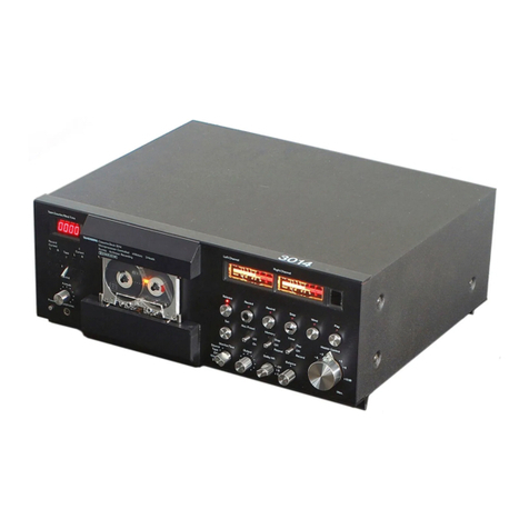
TANDBERG TCD 310 User manual

Service
Manual
Cassette
Deck
TANDBERG

CONTENTS
lz
Dsmanthings
.
24
-.teaw.
ah.
OR ee
3
1.1
Removal
of
top
plate.............
3
1.2
Removal
of
inner
top
plate
........
3
1.3
A
note
on
reassembling
...........
3
2.
Regular
maintenance
...............-
4
Peas
CHANTS
ok
cet,
Sees,
Gees
ee
ee
4
2
eoatssiney
8.
feet
ae
ee
ae
APOBAS
GATIONS.
grec’.
Cie
ae
wane
ey
a
3.
Mechanical
servicing
................
5
3.1
Microswitches
MS
1
and
MS
2......
5
3.2
Tape
path
adjustments
...........
5
Sealy
OUDMIME:
[ies
cn:
.
aie
=
oe
D
See
DeTaON
s
atid.
Tas
ous
oe
ee
6
3.3
Replacing
the
drive
belt...........
8
GPa
CAssene
AMM.
.
ms
he
eee
10
3.5
Pinch
roller
solenoid..............
10
DFO
WHalISe,
CONUEON
..
eat
Bete
ee
11
3.7
Adjusting
the
position
of
a
reel
motor
11
5.8
Salvaging
tangled
tape
............
11
4.
Motor
and
solenoid
circuits
...........
12
4,1
Solenoid
operating
circuit
.........
12
4,2
Motor
control
circuits
............
13
4.3
Control
of
motor
voltages
.........
13
5.
Electrical
adjustments
...............
14
6.
Circuit
diagrams....................
16

1.
DISMANTLING
Bal
REMOVAL
OF
TOP
PLATE
1.
Remove
the
plastic
lid
from
the
cassette
com-
partment,
and
push
the
compartment
down
to
closed
position.
2.
Remove
the
RECORD
LEVEL
buttons
(A).
Remove
the
3
screws
on
the
top
plate
(B)
and
the
3
screws
at
the
top
of
the
rear
plate
(C).
US-version
only:
Remove
the
nuts
from
the
microphone
sockets
(D).
3.
Grip
the
left
edge
of
the
cassette
compartment
aperture
with
your
fingers
(indicated
with
arrows
on.
the
drawing).
Remove
the
top
plate
by
lifting
the
rear
edge
first,
and
pulling
the
plate
away
from
the
recorder.
1.2
REMOVAL
OF
INNER
TOP
PLATE
The
inner
top
plate
with
indicators
and
volume
controls
can
be
lifted
to
the
vertical
position
to
give
access
to
the
electrical
parts.
1.
Remove
the
plastic
cover
of
the
indicators.
2.
Remove
the
left
side
wall
by
unscrewing
the
two
black
screws.
3.
Push
the
operating
buttons
(E)
out
to
the
left.
4.
Remove
the
plastic
arm
(F)
from
the
PAUSE
switch.
5.
Unscrew
the
6
screws
(G).
6.
Unhook
the
eject
interlock
arm
from
the
moving
plate
on
the
switch
bracket.
7.
Grip
the
right
edge
of
the
inner
top
plate
and
lift
it
carefully
to
vertical
position.
1.3
ANOTE
ON
REASSEMBLING
When
reassembling
make
sure
that
the
hooks
(J)
on
the
operating
buttons
are
hooked
onto
the
plastic
arms
on
the
switches.
Also
make
sure
that
the
eject
interlock
arm
is
hooked
onto
the
moving
plate
on
the
eject
switch
bracket.
Cassette
compartment
Plastic
cover
Inner
top
plate
Left
side
wall
Oe
ec
OCpoocoo
oF
(ohkenonek
chutenekokekenes
i
|
j
Profile
of
operating
button,

zZ
2.1
CLEANING
The
parts
of
the
cassette
deck
that
are
in
contact
with
the
tape
surface
should
be
cleaned
regularly,
otherwise
the
sound
quality
will
be
greatly
reduced.
Cleaning
of
capstans
and
pinch
rollers
is
particularly
important
to
avoid
wow
and
flutter.
If
the
cassette
deck
is
used
every
day,
cleaning
should
be
performed
at
least
once
a
month.
The
cleaning
can
be
done
with
cotton
wool
or
a
piece
of
flannel
wrapped
around
a
small
stick
and
moistened
with
pure
alcohol
or
methylated
spirit.
A
kit
intended
for
this
purpose,
Tandberg
Profes-
sional
Tape
Head
Cleaner”’,
is
available.
NOTE!
Do
not
use
solvents,
such
as
acetone
or
trichlor-
ethylene,
as
these
may
damage
the
heads.
How
to
clean
1.
Press
the
EJECT
button,
and
remove
the
plastic
lid
from
the
cassette
compartment.
2.
Push
the
cassette
compartment
down
to
closed
position.
3.
Clean
the
record/playback
head
(A),
erase
head
(B),
tape
guide
(C),
capstans
(D)
and
pinch
rollers
(E).
Do
not
use
too
much
cleaning
liquid
on
the
pinch
rollers,
and
dry
them
afterwards.
DO
NOT
USE
ANY
SHARP
OBJECTS
WHEN
CLEANING.
DO
NOT
TOUCH
THE
ADJUST-
MENT
SCREWS.
4.
Check
the
surrounding
area
for
dust
and
de-
posits
from
the
tape.
Clean
if
required.
Cleaning
should
be
performed
both
before
and
after
adjustments.
2.2
DEGAUSSING
A
marked
increase
in
background
noise
from
the
tape
may
indicate
that
the
heads
or
other
parts
in
the
tape
path
should
have
the
residual
magnetism
removed
(degaussing).
If
required,
degaussing
should
be
carried
out
as
follows.
Switch
off
the
deck.
Remove
the
cassette
from
the
deck.
Remove
the
plastic
4
REGULAR
MAINTENANCE
eco
he
fe
"a
se
Neen
f
PW
A
eaaeem
Pei
Rineasy,
Parts
to
be
cleaned
cassette
compartment
lid
and
move
the
de-
gausser
slowly
past
each
one
of
the
metal
parts
normally
in
contact
with
the
tape.
Take
great
care
not
to
let
the
degausser
touch
the
heads
or
metal
parts
in
the
tape
path.
Do
not
switch
off
the
de-
gausser
until
it
is
at
least
3
ft
from
the
deck.
Degaussing
should
be
performed
both
before
and
after
adjustments.
2.3
LUBRICATION
The
capstan
motor
and
the
reel
motors
may
require
lubrication
from
time
to
time.
The
interval
between
each
lubrication
should
be
at
least
3000
hours
of
operation.
Use
the
following
types
of
oil:
Capstan
motor:
ANDEROL
465
from
Tenneco
Chemicals,
U.S.A.,
or
oil
supplied
by
Tandberg.
Reel
motors:
NUTO
H36
(also
called
SPINESSO
34)
from
Esso.
NOTE!
Use
only
one
drop
of
oil
for
each
motor.

3.
MECHANICAL
SERVICING
3.1
MICROSWITCHES
MS
1
AND
MS
2
Pinch
rollers
released:
MS
1:
Check
that
there
is
a
gap
of
about
1
mm
between
the
connecting
arm
and
the
middle
leaf
of
the
switch
(see
figure).
MS
2:
Check
that
the
two
leaves
of
the
switch
are
pressed
together
between
the
solenoid
operating
lever
and
the
bracket.
Adjust
by
bending
the
bracket.
Pinch
rollers
operated:
MS
1:
Check
that
the
left
and
the
middle
leaf
are
pressed
together.
MS
2:
Check
that
the
switch
is
open.
3.2
TAPE
PATH
ADJUSTMENTS
The
following
equipment
is
needed:
—
An
ordinary
high
quality
cassette
which
has
been
cut
open
so
that
the
tape
is
visible
(see
figure).
—
Tandberg
test
tape
No.
23
(azimuth
test).
For
really
extensive
adjustments
—
for
example
if
several
parts
in
the
tape
path
are
replaced
—
a
Tandberg
Adjustment
Plate
may
be
needed.
Such
adjustments
should
be
carried
out
by
a
Tandberg
representative.
3.2.1
Outline
of
the
adjustment
procedure
Insert
an
open
cassette
and
set
the
deck
to
PLAY.
Check
that
the
tape
does
not
”climb”’
on
the
capstans
and
is
not
bent
or
folded
at
the
tape
guides.
Also
check
that
the
tape
does
not
”bulge”
at
the
heads
(’*bulging”
indicates
wrong
azimuth
adjustment
of
the
heads).
When
viewed
from
above
the
tape
should
be
seen
as
an
almost
invisible
line.
Also
check
that
the
top
of
the
erase
head
is
flush
with
the
top
edge
of
the
tape.
The
erase
head
should
not
be
visible
above
the
tape.
If
erratic
tape
motion
is
observed,
try
to
eliminate
it
by
turning
the
adjustment
screws
for
heads
or
pinch
rollers.
Insert
a
Tandberg
test
tape
No.
23
and
adjust
with
the
screw
(AZ)
on
the
record/playback
head
to
maximum
output
signals
on
both
OUTPUT
sockets.
The
difference
between
the
tracks
should
be
less
than
4
dB.
(Details:
see
next
page.)
Tandberg
Adjustment
Plate

3.2.2
Details
of
adjustment
procedure
@
Pinch
rollers.
Parallelity.
Move
the
mounting
plate
inwards
so
that
the
pinch
rollers
almost
touch
the
capstans.
Adjust
with
the
screws
(P)
so
that
both
rollers
are
parallel
with
the
capstans.
A
white
piece
of
paper
can
be
inserted
behind
the
pinch
roller
and
capstan
to
make
it
easier
to
see
the
gap
between
them.
Height.
Insert
the
open
cassette.
Move
the
mounting
plate
inwards
and
check
that
the
tape
fits
exactly
into
the
tape
guide
on
pinch
roller
1.
Adjust
with
the
two
screws
(H)
if
necessary
(turn
both
screws
equal
amounts).
Also
turn
the
azimuth
screw
(AZ)
correspondingly
in
the
opposite
direction
to
keep
the
roller
roughly
in
correct
azimuth
position.
Adjust
pinch
roller
2
to
corresponding
height.
This
adjustment
is
not
critical.
Azimuth.
Set
the
cassette
deck
to
PLAY
and
check
that
the
tape
does
not
”climb”
on
the
capstans.
If
necessary,
adjust
with
the
screws
(AZ).
Check
again
that
the
tape
is
not
bent
or
folded
at
the
tape
guide
of
pinch
roller
1.
Also
check
the
parallelity
again.
Height
and
azimuth
can
also
be
adjusted
by
means
of
a
Tandberg
Adjustment
Plate.
The
pinch
rollers
are
then
checked
against
the
tabs
marked
A
and
B
in
the
figure.
(A
special
adjustment
plate
for
the
pinch
roller
shafts
can
also
be
used).
Pinch
roller
operation.
Remove
the
cassette
and
move
the
mounting
plate
inwards.
Check
that
both
pinch
rollers
meet
the
capstans
at
exactly
the
same
time
(the
pinch
rollers
will
start
rotating
when
they
touch
the
capstans).
If
required,
adjust
with
the
eccentric
screw
as
shown.
@
Erase
head
The
position
of
the
erase
head
is
adjusted
by
turning
the
screws
on
the
head
mounting
plate
(see
top
figure
next
page
).
Preadjustment
of
head
mounting
plate.
Adjust
with
the
screws
(H)
and
(AZ)so
that
the
head
mounting
plate
is
parallel
with
the
underlying
mounting
plate.
The
gap
between
them
should
be
approx.
1
mm.
To
check
this,
the
right
chassis
plate
must
be
removed.
6
Height
Azimuth
Parallelity
Adjustment
screw
for
pinch
roller
operation
Preadjustment
of
head
mounting
plate

Adjustment
of
erase
head.
Insert
the
open
cassette
and
move
the
mounting
plate
inwards.
Adjust
with
the
screws
(H)
and
(AZ)
so
that
the
top
of
the
erase
head
is
flush
with
the
top
edge
of
the
tape.
The
front
of
the
erase
head
should
be
parallel
with
the
tape.
Set the
deck
to
PLAY.
Check
that
the
erase
head
is
not
visible
above
the
tape,
and
that
the
tape
does
not
bulge”
at
the
head.
Keep
the
head
mounting
plate
parallel
with
the
underlying
mounting
plate.
The
screws
(H)
must
not
be
unscrewed
too
far,
as
the
spring
under
the
head
mounting
plate
will
then
prevent
the
mounting
plate
from
moving
freely.
An
Adjustment
Plate
can
also
be
used.
In
this
case
the
top
of
the
erase
head
should
be
flush
with
tab
D.
The
front
of
the
erase
head
should
be
parallel
with
the
tab.
M@
Record/playback
head
The
position
of
the
record/playback
head
is
adjusted
by
turning
the
screws
on
the
head
bracket.
Do
not
touch
the
adjustment
screws
for
the
head
mounting
plate.
It
is
assumed
that
the
head
mounting
plate
has
already
been
correctly
adjusted
Height
and
parallelity.
Insert
the
open
cassette
and
move
the
mounting
plate
inwards.
Adjust
with
the
screws
(H)
and
(P)
so
that
the
tape
fits
exactly
into
the
tape
guide
of
the
head.
The
front
of
the
head
should
be
parallel
with
the
tape.
Set
the
deck
to
PLAY.
Check
again
that
the
tape
is
not
bent
or
folded
at
the
tape
guide,
and
does
not
*bulge’’
at
the
head.
Azimuth.
Insert
a
Tandberg
test
Tape
No.
23
(6,300
Hz
azimuth
test).
Connect
a
voltmeter
to
each
OUTPUT
socket
and
set
the
deck
to
PLAY.
Adjust
with
the
screw
(AZ)
to
maximum
output
signals
with
no
more
than
4
dB
difference
between
the
tracks
(adjust
to
best
compromise).
Check
the
height
and
parallelity
again,
and
re-
adjust
if
necessary.
If
readjustments
are
made,
the
azimuth
must
be
checked
again.
If
an
Adjustment
Plate
is
used,
the
parallelity
must
be
checked
against
tab
F,
and
the
height
against
tab
E.
Do
not
turn
the
screws
while
the
tape
guide
of
the
head
touches
tab
E
as
this
may
cause
bending
of
the
tape
guide.
Tracking
control.
Insert
an
ordinary
cassette
and
record
a
signal
on
both
tracks.
Then
turn
the
cassette
around
and
set
the
deck
to
PLAY.
Listen
for
crosstalk
on
the
recorded
piece
of
tape.
Head
mounting
plate
Right
chassis
plate
Adjustment
screws
for
erase
head
Tandberg
Adjustment
Plate
Adjustment
screws
for
record/playback
head
Open
cassette

3.3.
REPLACING
THE
DRIVE
BELT
Before
starting
this
operation
remove
the
top
plate
and
the
cassette
compartment
lid.
1.
Wind
a
piece
of
sellotape
a
few
times
around
each
capstan
(see
fig.).
This
is
done
to
ensure
that
the
capstans
and
flywheels
will
stay
in
place
during
the
dismantling.
2.
Unhook
the
connecting
spring
from
the
mounting
plate.
Be
sure
to
note
which
notch
the
spring
is
fastened
to,
so
that
you
will
be
able
to
replace
it
correctly.
3.
|
Unhook
the
drive
belt
from
the
pulley.
4.
Remove
the
circlip
on
the
front
side
of
the
cassette
compartment
(see
fig.).
5.
Unhook
the
locking
lever
from
the
cassette
compartment.
The
cassette
compartment
can
now
swing
upwards.
6.
Unscrew
the
two
screws
(B)
holding
the
guide
brackets
for
the
mounting
plate.
7.
Unhook
the
two
guide
brackets
and
pull
them
out
through
the
holes
(C).

8.
Remove
the
mounting
plate
carefully.
1
12.
13.
14.
Unscrew
the
three
screws
(D)
holding
the
flywheel
mounting
plate
and
—
—
lift
out
the
flywheel
mounting
plate
with
capstans
and
flywheels.
Remove
the
old
drive
belt.
Place
the
new
drive
belt
around
the
flywheels
and
hook
it
around
the
cassette
guides
(see
fig.)
TAKE
CARE
NOT
TO
GET
OIL
OR
GREASE
ON
THE
DRIVE
BELT.
Replace
the
flywheel
mounting
plate
and
hook
the
drive
belt
around
the
pulley.
NOTE!
The
drive
belt
should
pass
under
the
counter
drive
belt.
Replace
the
mounting
plate
and
check
that
it
runs
freely
back
and
forth.
Add
a
little
grease
on
the
ball
bearings
if
required.
se
Mobilplex
grease
No.
47
or
equivalent.
Replace
all
other
parts.
Remove
the
sellotape
from
the
capstans
and
CLEAN
THE
CAP-
STANS
THOROUGHLY.
Insert
a
cassette
and
check
that
the
tape
does
not
stick
to
the
capstans.

3.4
CASSETTE
ARM
The
cassette
arm
can
be
adjusted
by
bending
the
end
which
normally
rests
against
the
cassette
(see
figure).
Insert
a
cassette,
close
the
cassette
compartment
and
check
the
following:
—
The
cassette
should
rest
against
the
cassette
guides.
—
Microswitch
MS
4
should
be
closed.
(If
neces-
sary,
MS
4
can
be
adjusted
by
bending
the
support
bracket
for
the
microswitch).
—
The
locking
lever
extending
from
the
cassette
compartment
and
down
through
a
slot
in
the
motor
support
plate
should
be
about
2
mm
from
the
right
end
of
this
slot
(see
figure).
NOTE!
If
the
cassette
arm
is
bent
too
much
to
the
right,
the
locking
lever
will
be
moved
so
far
to
the
left
that
it
will
not
lock
the
cassette
compartment
in
the
lower
position.
—
When
the
cassette
compartment
is
released,
the
cassette
arm
should
push
the
cassette
half-way
out
of
the
compartment.
3.5
PINCH
ROLLER
SOLENOID
1.
Set
the
deck
to
play.
2.
Check
that
the
connecting
spring
is
stretched
approximately
0.5
-
0.7
mm.
The
figure
shows
how
this
check
is
made.
(Lhe
microswitches
are
not
shown
in
the
figure).
3.
If
necessary,
adjust
by
turning
the
nylon
screw
in
the
armature
of
the
solenoid.
To
reach
this
screw:
Switch
off
the
power,
lift
the
inner
top
plate
(with
the
indicators)
to
vertical
position.
Adjust
by
angling
the
screwdriver
towards
the
armature
from
the
left.
4.
Check
with
a
gauge
that
the
force
needed
to
lift
the
pinch
rollers
away
from
the
capstans
is
1000
-
1200
grams.
5.
If
necessary,
this
force
can
be
adjusted
by
moving
the
connecting
spring
to
another
notch.
If
the
spring
is
moved,
the
spring
tension
must
be
checked
again
as
explained
in
2.
10
Position
of
locking
lever
(cassette
in
compartment)
Spring
tension
(cassette
deck
in
PLAY)
Pinch
roller
pressure

3.6
PAUSE
CONTROL
When
the
PAUSE
button
is
depressed,
the
gap
between
pinch
rollers
and
capstans
can
be
adjusted
with
a
screw
marked
*PAUSE
ADJUST”,
which
can
be
reached
by
removing
the
right
side
wall.
Insert
a
cassette
and
set
the
deck
to
PLAY.
Depress
the
PAUSE
button
a
few
times,
and
check
the
following:
—
The
PAUSE
lever
should
move
freely,
without
touching
the
motor
support
plate
or
the
bracket
of
the
PAUSE
switch.
(If
required,
this
bracket
can
be
bent
a
little
with
a
screwdriver.)
—
When
the
PAUSE
button
is
depressed,
the
tape
should
stop,
and
the
pinch
rollers
should
be
lifted
away
from
the
capstans.
The
gap
must
be
wide
enough
that
neither
of
the
pinch
rollers
touch
the
capstans
under
any
circumstance.
If
required,
adjust
with
the
PAUSE
ADJUST
screw.
—
At
the
same
time,
the
gap
must
be
so
narrow
that
the
pinch
roller
solenoid
will
pull
the
pinch
rollers
in
again
when
the
PAUSE
button
is
re-
leased,
both
during
PLAY
and
RECORD.
IMPORTANT!
With
the
deck
in
PLAY,
release
the
PAUSE
button
and
check
that
the
PAUSE
lever
can
be
moved
a
little
up
and
down
(as
indicated
with
an
arrow
in
the
figure).
If
the
lever
cannot
be
moved,
the
reason
is
probably
that
the
PAUSE
ADJUST
screw
butts
against
the
lever,
and
the
force
of
the
pinch
roller
solenoid
is
transferred
to
the
lever.
The
pressure
of
the
pinch
rollers
is
then
correspondingly
reduced.
3.7
ADJUSTING
THE
POSITION
OF
A
REEL
MOTOR
Insert
a
high
quality
cassette
and
close
the
cassette
compartment.
Check
that
the
tape
spindle
on
the
motor
is
exactly
in
the
center
of
the
correspond-
ing
hub
on
the
cassette.
Try
the
recorder
in
play,
wind
and
rewind.
Check
that
the
hub
runs
easily
and
does
not
wobble.
If
necessary,
adjust
by
loosening
the
two
screws
holding
the
reel
motor.
This
will
be
easier
if
you
remove
the
circlip
on
the
left
side
of
the
cassette
compartment
and
swing
the
cassette
compartment
upwards
(see
page
8,
step
4).
The
ree]
motor
can
now
be
moved
slightly.
3.8.
SALVAGING
TANGLED
TAPE
Occasionally
the
tape
will
wind
itself
around
the
last
of
the
two
capstans.
To
salvage
the
tape
proceed
as
follows:
1.
Remove
the
bottom
plate
of
the
deck.
2.
Turn
the
flywheel
of
the
entangled
capstan
slowly
against
its
normal
rotation.
Use
your
finger
to
turn
the
flywheel.
3.
When
the
tape
has
been
untangled
from
the
capstan,
wind
it
manually
onto
the
hubs
of
the
cassette.
Turning
the
flywheel
in
order
to
salvage
tangled
tape
11

4.
MOTOR
AND
SOLENOID
CIRCUITS
4.1
ASHORT
EXPLANATION
OF
THE
SOLENOID
OPERATING
CIRCUIT
(0305,
0306)
Operation
of
the
pinch
roller
(start)
solenoid
should
be
slightly
delayed,
to
give
the
reel
motors
time
to
remove
any
slack
in
the
tape,
before
the
pinch
rollers
are
pulled
in.
When
both
PLAY
and
RECORD
buttons
are
re-
leased,
C316
has
no
voltage
and
Q307
(PNP)
is
cut-
off.
Q306
(NPN)
has
a
base
voltage
of
0
V
and
is
also
cut-off.
When
the
PLAY
or
RECORD
button
is
depressed
the
following
sequence
is
started:
1.
12
START
/
STOP
CIR
cu
DO
AR
2068
13.5
V
is
connected
to
the
+side
of
C316.
The
voltage
drop
over
R326
gives
Q307
an
emitter
voltage
of
about
11
V.
The
transistor
requires
a
base
voltage
which
is
0.7
V
more
negative
than
the
emitter
to
start
conducting.
The
transistor
|
will
therefore
still
be
in
cut-off
state.
Jcsirare
te
Solenoid
operating
circuit
.
C316
is
charged
through
R328/R333.
The
posi-
tive
voltage
at
point
A
is
connected
via
C315
to
the
base
of
Q307.
This
voltage
is
gradually
reduced
as
C316
is
charged.
.
After
a
little
while,
the
voltage
at
point
A
has
been
reduced
so
much
that
the
base
of
Q307
drops
lower
than
10.3
V,
and
the
transistor
starts
conducting.
.
When
Q307
starts
conducting,
the
collector
voltage
increases,
driving
Q306
into
conducting
state.
Point
B
is
connected
to
ground,
current
passes
through
the
activate”
coil
(Ly)
of
the
start
solenoid
and
the
pinch
rollers
operate.
.
When
Q306
is
conducting,
the
current
to
C316
passes
through
R332
and
Q306,
C316
will
there-
fore
be
fully
charged
in
a
very
short
time.
.
When
C316
is
fully
charged,
there
will
be
no
voltage
at
point
A,
and
C315
is
charged
through
R325,
The
current
through
R325
will
keep
Q307
in
conducting
state.
.
After
a
little
while
the
current
to
C315
has
been
reduced
so
much
that
Q307
goes
cut-off.
Q306
also
goes
cut-off,
stopping
the
current
through
the
activate”
coil.
START
Ty
SOLENDIC

4.2
A
SHORT
EXPLANATION
OF
THE
MOTOR
CONTROL
CIRCUITS
When
the
reel
motors
revolve,
they
generate
pulses.
These
pulses
are
used
to
control
the
motor
power
supply.
When
both
motors
are
stationary,
no
pulses
are
fed
to
the
motor
signal
amplifier.
Q504
of
the
Schmitt-
trigger
is
cut-off,
and
Q505
is
conducting.
Q507
is
also
conducting,
and
the
motor
power
supply
is
connected
to
ground.
Therefore,
no
voltage
is
fed
to
the
motors.
When
the
REWIND,
WIND,
PLAY
or
RECORD
button
is
depressed,
one
of
the
capacitors
C317,
C320
or
C321
will
give
a
trigger
pulse
to
the
Schmitt-trigger.
Q504
starts
conducting
and
Q505
goes
cut-off.
Q507
also
goes
cut-off,
and
the
motor
power
supply
feeds
a
voltage
to
the
motors
(via
microswitches
and
operating
switches).
‘The
motors
start
revolving,
feeding
pulses
to
the
motor
signal
amplifier.
The
output
from
this
amplifier
will
keep
Q504
in
conducting
state.
During
wind
or
rewind
the
supply
motor
works
as
a
generator,
feeding
a
negative
voltage
to
transistor
Q506,
which
regulates
the
motor
power
supply.
The
voltage
from
the
power
supply
is
therefore
dependent
on
the
speed
of
the
supply
reel.
When
the
tape
stops
(for
instance
at
the
end
of
the
tape)
the
input
to
the
motor
signal
amplifier
drops
to
zero,
and
the
Schmitt-trigger
reverts
to
unope-
rated
state
after
a
short
delay
(determined
by
C508/R512).
Q507
starts
conducting
and
the
voltage
from
the
motor
power
supply
drops
to
zero.
4.3
CONTROL
OF
MOTOR
VOLTAGES
Remove
the
bottom
plate,
insert
a
cassette
in
the
deck
and
check
that
the
voltages
across
the
motors
are
as
specified
below:
OV
0.7V~0.8V
|
0.7V—-08V
Drops
to
0
Drops
to
0
after
a
short
after
a
short
while
while
10V~3.5V
Drops
to
0a
little
while
after
the
end
stop
is
reached
10V—3.5V
Drops
to
0a
little
while
after
the
end
stop
is
reached
Block
diagram
of
motor
control
circuits
13

5.
ELECTRICAL
ADJUSTMENTS
GENERAL
.
NECESSARY
EQUIPMENT
—
”0
dB”
level
is
defined
as
775
mV.
Thus
—5
dB
—
2high
impedance
voltmeters
(do
NOT
use
equals
450
mV
and
—35
dB
equals
14
mV.
universal
meters).
—
Frequency
counter.
; .
;
;
—
Audio
generator.
—
Make
the
adjustments
in
the
order
in
which
they
are
listed
here.
Many
of
the
adjustments
require
that
previous
adjustments
have
already
been
—
Wow
meter
(required
for
wow
test
only).
correctly
made.
It
is
especially
important
that
adjustment
for
CrOg
tape
be
made
before
adjust-
ment
for
HL
tape.
—
Tandberg
test
tapes
No.
21
(1,000
Hz
speed
test),
No.
22
(3,150
Hz
wow
test),
No.
23
(6,300
Hz
azimuth
test)
and
No.
24
(1,000
Hz
playback
™
level).
—
TDK
C60
CHROM
or
equivalent
chromium
dioxide
cassette.
—
Distortion
meter.
—
Hum/noise
meter
(required
for
signal/noise
test).
—
Clean
and
degauss
the
tape
path
before
and
after
the
adjustments.
It
is
assumed
that
the
tape
path
has
already
been
correctly
adjusted
as
described
on
pages
5,
6
and
7.
—
Maxell
C60
UD
or
equivalent
HL
cassette.
Location
of
test
points
and
adjustable
components:
see
page
17
Azimuth
Adjust
to
best
signal.
Difference
screw
on
|compromise
between
the
tracks:
|
head
<
4¢dB
1775
mV
R317
(left
ch.)
R417
(right
ch.
Playback
c
+
1%
(990
—
1010)
Playback
S
0.2%
Measure
at
end
of
{DIN
45,507
tape.
Measure
both
peak
weighted)
in
vertical
and
hori-
45.507)
zontal
position
CrO2
Frequency
|Connect
80
-
100
kHz
Connection
is
made
Recording
counter
inductively
with
a
coil
or
a
few
to
erase
turns
of
ordinary
head
(see
wire.
Instead
of
a
comments)
frequency
counter
a
long-wave
receiver
(
tuned
to
3rd
har-
monic)
can
be
used
|
CrO2
Voltmeter
[Across
[28
—
32
V
Recording
lerase
head
CrO2
Voltmeters
[OUTPUT
|<
5
mv
lps
INPUT
sockets
open
|
Recording
|
sockets
=
CrO2
Voltmeters
[R319
(left)
[Minimum
L301
{left
ch.)
|
The
filters
prevent
Recording
R419
(right)|reading
L401
(right
ch.)
|
the
record
amplifiers
to
ground
\{2—4
V}
from
short-circuiting
the
bias
voltage
to
ground
130!
-===4
TO
REC
/PLAY
HEAD
TO
OUTPUT
OF
REC
AMP
cH
RTS

Voltmeters
|
R801
(left
ch.)
CrOz
|
Voltmeters
|Set
the
cassette
deck
to
CrO2
recording
and
adjust
R901
{right
ch.)
|€801
(left
ch.)
and
C901
(right
ch.)
to
readings
of
see
“location’’
drawing
OUTPUT
sockets
approximately
6—8
mV.
(Measure
between
ground
and
the
side
of
the
resistor
which
is
connected
to
the
head.)
Set
the
cassette
deck
to
CrO2
recording.
R1
and
R2
to
mid-position.
Connect
an
audio
generator
to
the
INPUT
sockets.
Adjust
the
jgenerator
to
400
Hz,
-5
dB
(=
450
mV
on
the
voltmeters).
(—5
dB
is
used
instead
of
0
dB
in
order
to
avoid
inaccurate
results
caused
by
varying
tape
characteristics.
y
varying
tap
)
Bakes
output
Rewind
and
play
back.
The
voltmeters
should
now
read
—5
dB
(=450
mV)
+
0.5
dB.
If
outside
the
tolerance,
make
a
new
recording
while
adjusting
R105
(left
ch.)
and
R205
(right
ch.)
as
required.
Then
play
back
and
check
once
more.
Voltmeters
Distortion
meter
Voltmeters
CrQ2
|
Indicators
Mian
aa
Voltmeters
HL
HL
Voitmeters
|
i
H
Distortion
meter
;
HL
Voltmeters.
Voltmeters
Hum/noise
meter
(according
to
DIN
45.405)
OUTPUT
sockets
OUTPUT
sockets
OUTPUT
sockets
OUTPUT
sockets
OUTPUT
sockets
OUTPUT
sockets
OUTPUT
sockets
Set
the
cassette
deck
to
CrOg
recording.
Adjust
the
generator
to
—35
dB
{=
14
mV
on
the
voltmeters)
and
record
a
400
Hz
and
a
10,000
Hz
signal
at
this
level.
Rewind
and
play
back.
Use
the
400
Hz
signal
as
a
reference
and
check
on
both
channels
that
the
10,000
Hz
signal
is
within
the
following
tolerance:
-0
dB
to
+5
dB.
If
outside
the
tolerance
adjust
C801
and
C901
(bias).
Then
make
a
new
recording,
play
back
and
check
once
more.
Set
the
cassette
deck
to
CrOg
recording.
Generator
to
1000
Hz,
0
dB
(=775
mV
on
the
voltmeters).
Rewind
and
play
back.
Check
that
the
distortion
is
S
5%
(3rd.
harmonic
distortion
according
to
DIN
45,405).
If
outside
the
tolerance
adjust
C801
and
C901
(bias).
Make
a
new
Set
the
cassette
deck
to
CrO2?
DOLBY
(!)
recording.
Adjust
the
generator
to
—35
dB
and
record
the
following
frequencies:
400
Hz,
55
Hz,
1000
Hz,
4000
Hz,
10,000
Hz,
12,500
Hz.
Rewind
and
play
back.
Use
the
400
Hz
signal
as
a
referance,
and
check
that
the
other
signals
are
within
the
following
tolerances:
55
Hz:
~3
dB
to
+2
dB
10,000
Hz:
OdBto+
5B
1000
Hz:
~2
dB
to
+2
dB
12,500
Hz:
—2
dB
to
+
5
4B
4000
Hz:
—2
dB
to
+4
dB
If
outside
the
tolerances
try
changing
the
values
of
Cb01/C502
(left
ch.)
and
€601/C602
(right
ch.).
Increased
values
give
higher
treble
response.
Record
a
400
Hz,
0
dB
signal
and
adjust
R115
(left
ch.)
and
R215
(right
ch.)
to
0
dB
deflection
on
both
indicators.
Same
as
in
step
9.2,
except
that
the
CrOg
button
is
released.
If
outside
the
tolerance
adjust
R104
(left
ch.)
and
R204
(right
ch.).
DO
NOT
TOUCH
R105
OR
R205.
NOTE!
Adjustment
of
R104
and
R204
will
not
affect
the
readings
on
the
indicators
of
the
cassette
deck.
Same
as
in
step
9.3,
except
that
the
CrO9
button
is
released,
If
outside
the
tolerance
adjust
R807.
DO
NOT
TOUCH
C801
OR
C901.
Same
as
in
step
9.4,
except
that
the
CrOg
button
is
released.
If
outside
the
tolerance
adjust
R807.
Then
repeat
11.2.
DO
NOT
TOUCH
C801
OR
C901.
Same
as
in
step
9.5,
except
that
the
CrO9
button
is
released.
Tolerances:
55
Hz:
—3
dB
to
+2
dB
10,000
Hz:
—2
dB
to
+5
dB
1000
Hz:
—-2
dB
to
+2
dB
12,500
Hz:
—3
dB
to
+4
dB
4000
Hz:
-2
dB
to
+4
dB
If
outside
the
tolerances
try
changing
the
values
of
C503/C510
(left
ch.)
and
C603/C604
(right
ch.).
Increased
values
give
higher
treble
response.
Record
a
400
Hz,
0
dB
signal.
Rewind
and
erase.
Then
rewind
once
more
and
play
back
the
erased
piece.
The
voltmeters
should
read
<—
62
cB.
The
signal/noise
ratios
at
5
%
distortion
should
be
at
least
as
good
as
specified
in
the
table
below:
NORMAL
DOLBY
Signal/tape
noise:
HL
CrO2
HL
CrO2
DIN
45.511
(Gerauschspannung)
46
dB
49
dB
55dB
58
dB
DIN
45.511
(Fremdspannung)
46dB
48dB
50dB
50
dB

Oscillator
|
|]
Dolby
boards
104
@)
sot
503]
C603
“A208
=
|
Amplifier
2
board
fa)
i)
a
RNIB
R108
A205
A216
A31
'®
Mue
Amplifier
I
board
SRE
30m
BRO)
1
C80’
Ago
C901
AZIMUTH
1407
L301
=X
|
woo
Gl...
Location
of
test
points
and
adjustable
components

Oscillator
|
|]
Dolby
boards
104
@)
sot
503]
C603
“A208
=
|
Amplifier
2
board
fa)
i)
a
RNIB
R108
A205
A216
A31
'®
Mue
Amplifier
I
board
SRE
30m
BRO)
1
C80’
Ago
C901
AZIMUTH
1407
L301
=X
|
woo
Gl...
Location
of
test
points
and
adjustable
components

Dolby
boards
roa
©
cor
©
conn
R215,
Amplifier
2
board
g
is)
A
ATS
R105
R205
cits
@
aL
Amplifier
1
beard
_
Location
of
test
points
and
adjustable
components
Dolby
board
Oscillator
board

Amplifier
1
board
=}
=
>
au
09:
¥,
be
Ae
H*
g
a
Ss
@)
|
@—Toicut
car
a5,
;
e050
©
eer
am
il!
-
fa
>
Sho
~
Ba
ara
a
3g
t
og
WATTS
a
om
&
8
is)
es)
N
&
8
&
3
Q
=
x

ee
ee
ee
ee
BOARO
NO
60209
|
|
|
|
|
|
|
|
I
|
|
|
|
|
|
|
[
|
|
[
|
!
|
|
|
|
|
Vas5
|
V3
MIC.
/
LINE
AMP
RIGHT
AMPLIFIER
I
Ov
All
voltages
are
measured
with
VTV.M
with
input
Impedance
min
10M
ohms
Ail
DC
voltages
measured
without
signal
Ged)
Denotes
signal
volieges
(1000Hz)
TmV
Denotes
OC
voltages
{10V}
Denotes
voltages
in
operated
mode
RECORD
LEVEL
LEFT
i
362
42
320
REWIND
7
z
a
sToP
WIND
i
-—4
ma
|
ke
Remo
paberviu
sins
¢
ay
Se
ie
1}...
START/
STOP
CIRCUIT
CAIs
CAG
0p
1000p
RECORD
LEVEL
RIGHT
Le
Lett
channel
{Track
|
or
tale
3
4701
L702
&
=--4
=~
13.5V
>
“
EEE
MS3
NS
MS&
REC
SUDE
CASSETTE
680
p
4)
Re
Right
channel
[Track
2
oF
3)
—}
=
Connector
O10)
=
Connection
terminel
Signal
path
—
RECORDING
Signal
path
—
PLAYBACK
~
:.
9°
]
J
MS2
MUTING
123
104
{750}
Ra
+4
\j
ae
f
:
r|
U3,
a
Ls
ea
aS,
337
Green
Z
Blue
304!
+234
Start
—————
8
fis
SOLENQIC
as!
JPLAYE,
Bb
(Se
MOTOR
SIGNAL
AMPLIFIER
ee
SE
ES
BC
147
BC
1498
Be
169
---p>---
TRANSIS
E(D)
Ge
ctG)
2N5087
MPS
6518
(2N5458)
TORS SEEN
FROM
UNDERNEATH
Other manuals for TCD 310
1
Table of contents
Other TANDBERG Cassette Player manuals

TANDBERG
TANDBERG 10X User manual
TANDBERG
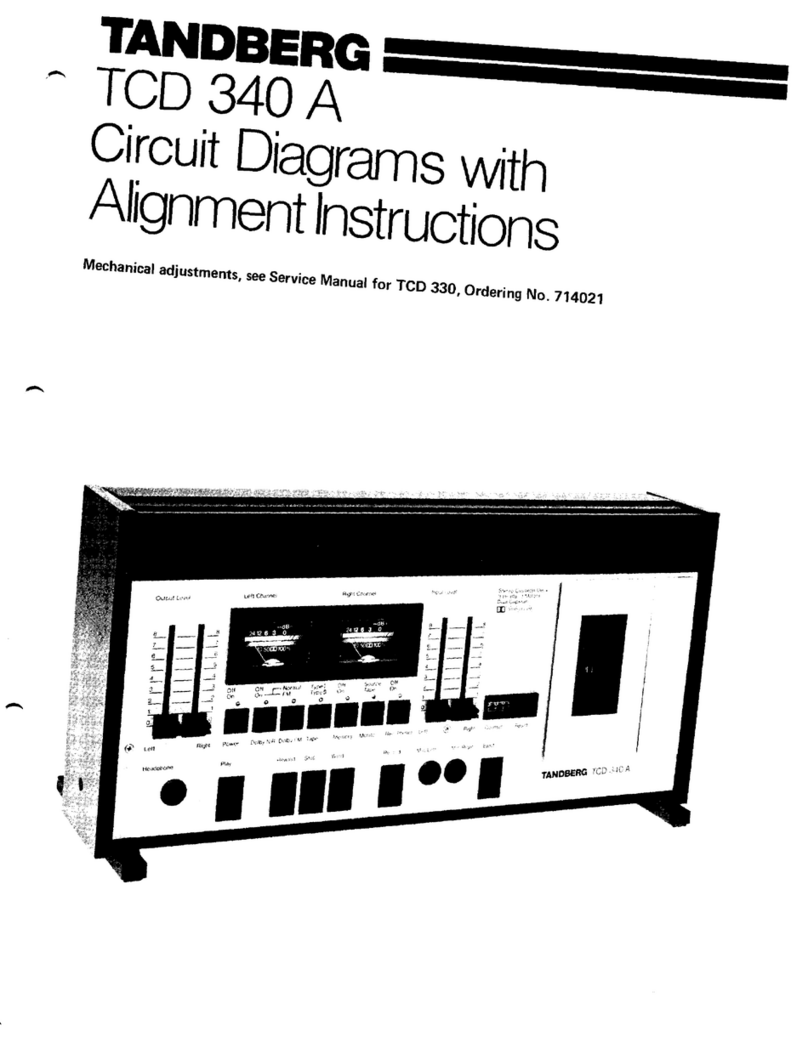
TANDBERG TCD 340 A User manual

TANDBERG
TANDBERG EDUCATIONAL TCR 222 User manual

TANDBERG
TANDBERG 6000X Series User manual

TANDBERG
TANDBERG TCD 910 User manual

TANDBERG
TANDBERG TCD 340A User manual

TANDBERG
TANDBERG TCD 42OA User manual

TANDBERG
TANDBERG TCD 3034 User manual

TANDBERG
TANDBERG TCD 310 User manual

TANDBERG
TANDBERG TCD-3014A User manual