T&D VEGAWELL 52 User manual

Operating Instructions
VEGAWELL 52
4…20 mA
Document ID:
35401
Process pressure/
Hydrostatic

Contents
1About this document
1.1Function.................................. 4
1.2Target group .............................. 4
1.3Symbolism used............................ 4
2For your safety
2.1Authorised personnel ........................ 5
2.2Appropriate use ............................ 5
2.3Warning about misuse ....................... 5
2.4General safety instructions .................... 5
2.5Safety label on the instrument .................. 6
2.6CE conformity ............................. 6
2.7NAMUR recommendations .................... 6
2.8Safety instructions for Ex areas ................. 6
2.9Environmental instructions..................... 6
3Product description
3.1Structure ................................. 7
3.2Principle of operation ........................ 8
3.3Operation................................. 9
3.4Packaging,transport and storage ............... 9
3.5Accessories and replacement parts .............. 10
4Mounting
4.1General instructions ......................... 11
4.2Mounting steps with straining clamp ............. 12
4.3Mounting steps with screwed connection .......... 13
4.4Mounting steps with threaded connection or housing .14
5Connecting to power supply
5.1Preparing the connection ..................... 15
5.2Connection procedure........................ 17
5.3Wiring plan................................ 18
5.4Switch-on phase............................ 19
6Maintenance and fault rectification
6.1Maintenance .............................. 21
6.2Remove interferences........................ 21
6.3Shorten suspension cable ..................... 22
6.4Shorten suspension cable ..................... 22
6.5Instrument repair ........................... 24
7Dismounting
7.1Dismounting steps .......................... 25
7.2Disposal ................................. 25
8Supplement
8.1Technical data ............................. 26
2VEGAWELL 52 •4…20 mA
Contents
35401-EN-111021

8.2Dimensions ............................... 32
Supplementary documentation
Information:
Supplementary documents appropriate to the ordered version come
with the delivery.You can find them listed in chapter "Product
description".
Editing status:2011-10-10
VEGAWELL 52 •4…20 mA3
Contents
35401-EN-111021

1About this document
1.1Function
This operating instructions manual provides all the information you
need for mounting,connection and setup as well as important
instructions for maintenance and fault rectification.Please read this
information before putting the instrument into operation and keep this
manual accessible in the immediate vicinity of the device.
1.2Target group
This operating instructions manual is directed to trained qualified
personnel.The contents of this manual should be made available to
these personnel and put into practice by them.
1.3Symbolism used
Information,tip,note
This symbol indicates helpful additional information.
Caution:If this warning is ignored,faults or malfunctions can
result.
Warning:If this warning is ignored,injury to persons and/or serious
damage to the instrument can result.
Danger:If this warning is ignored,serious injury to persons and/or
destruction of the instrument can result.
Exapplications
This symbol indicates special instructions for Ex applications.
lList
The dot set in front indicates a list with no implied sequence.
àAction
This arrow indicates a single action.
1Sequence
Numbers set in front indicate successive steps in a procedure.
4VEGAWELL 52 •4…20 mA
1About this document
35401-EN-111021

2For your safety
2.1Authorised personnel
All operations described in this operating instructions manual must be
carried out only by trained specialist personnel authorised by the plant
operator.
During work on and with the device the required personal protective
equipment must always be worn.
2.2Appropriate use
VEGAWELL 52 is a suspension pressure transmitter for level and
gauge measurement.
You can find detailed information on the application range in chapter
"Product description".
Operational reliability is ensured only if the instrument is properly used
according to the specifications in the operating instructions manual as
well as possible supplementary instructions.
For safety and warranty reasons,any invasive work on the device
beyond that described in the operating instructions manual may be
carried out only by personnel authorised by the manufacturer.Arbitrary
conversions or modifications are explicitly forbidden.
2.3Warning about misuse
Inappropriate or incorrect use of the instrument can give rise to
application-specific hazards,e.g.vessel overfill or damage to system
components through incorrect mounting or adjustment.
2.4General safety instructions
This is a high-tech instrument requiring the strict observance of
standard regulations and guidelines.The user must take note of the
safety instructions in this operating instructions manual,the country-
specific installation standards as well as all prevailing safety
regulations and accident prevention rules.
The instrument must only be operated in a technically flawless and
reliable condition.The operator is responsible for trouble-free
operation of the instrument.
During the entire duration of use,the user is obliged to determine the
compliance of the necessary occupational safety measures with the
current valid rules and regulations and also take note of new
regulations.
VEGAWELL 52 •4…20 mA5
2For your safety
35401-EN-111021

2.5Safety label on the instrument
The safety approval markings and safety tips on the device must be
observed.
2.6CE conformity
This device fulfills the legal requirements of the applicable EC
guidelines.By attaching the CE mark,VEGA provides a confirmation
of successful testing.You can find the CE conformity declaration in the
download area of www.vega.com.
2.7NAMUR recommendations
NAMUR is a user association for automation technology in the process
industries in Germany.Several of its key activities are defining
standards as well as setting user requirements on new devices,
systems and technologies.The published NAMUR recommendations
(NE)are accepted as the standard in field instrumentation.
The device fulfills the requirements of the following NAMUR
recommendations:
lNE 21 –Electromagnetic compatibility of equipment
lNE 43 –Standardization of the signal level for the breakdown
information of digital transmitters
2.8Safety instructions for Ex areas
Please note the Ex-specific safety information for installation and
operation in Ex areas.These safety instructions are part of the
operating instructions manual and come with the Ex-approved
instruments.
2.9Environmental instructions
Protection of the environment is one of our most important duties.That
is why we have introduced an environment management system with
the goal of continuously improving company environmental protection.
The environment management system is certified according to DIN
EN ISO 14001.
Please help us fulfil this obligation by observing the environmental
instructions in this manual:
lChapter "Packaging,transport and storage"
lChapter "Disposal"
6VEGAWELL 52 •4…20 mA
2For your safety
35401-EN-111021

3Product description
3.1Structure
The scope of delivery encompasses:
lVEGAWELL 52 pressure transmitter with suspension cable
loptionally available with straining clamp,screwed connection or
housing with cable locking
lDocumentation
-this operating instructions manual
-test certificate
-Supplementary instructions "Suitable for drinking water"(op-
tional)
-Ex-specific"Safety instructions"(with Ex versions)
-if necessary,further certificates
VEGAWELL 52 with suspension cable consists of the following
components:
lTransmitter
lSuspension cable
lOptional fastening element or housing with threaded fitting
The components are available in different versions.
2
1
Fig.1:Example of a VEGAWELL 52 with transmitter 22 mm
1Transmitter
2Suspension cable
Scope of delivery
Constituent parts
VEGAWELL 52 •4…20 mA7
3Product description
35401-EN-111021
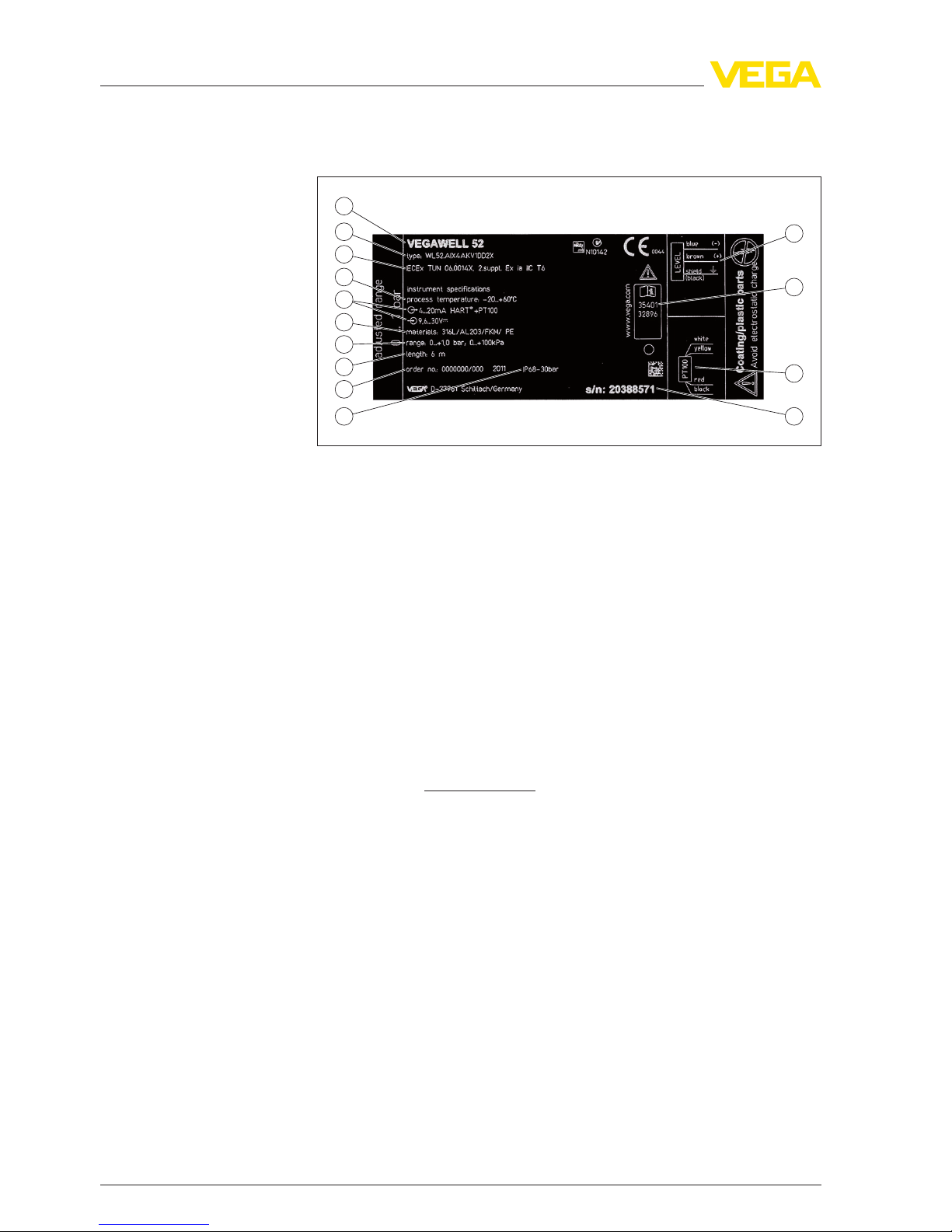
The type label contains the most important data for identification and
use of the instrument:
1
2
3
4
5
7
8
9
10 11
12
13
14
6
Fig.2:Structure type label VEGAWELL 52 (example)
1Instrument type
2Product code
3Approvals
4Process temperature
5Signal output/Voltage supply
6Materials transmitter/Measuring cell/Measuring cell seal/Connection cable
7Measuring range
8Cable length
9Order number
10 Protection rating
11 Serial number of the instrument
12 Assignment connection cable temperature
13 ID numbers,instrument documentation
14 Assignment connection cable level
The serial number allows you to access the delivery data of the
instrument via www.vega.com,"VEGA Tools"and "serial number
search".You can also find the serial number on the type label on the
suspension cable or on the housing.
3.2Principle of operation
VEGAWELL 52 is used for level and gauge measurement in wells,
basins and vessels open to the atmosphere,particularly in the water/
waste water industry as well as in the shipbuilding industry.1)
The actual sensor element is the CERTEC
®
measuring cell with
rugged ceramic diaphragm.The hydrostatic pressure causes a
capacitance change in the measuring cell via the ceramic diaphragm.
This change is converted into an appropriate output signal.
1)For use in closed vessels under vacuum,the instrument is available with
absolute pressure measuring ranges.
Type label
Application area
Functional principle
8VEGAWELL 52 •4…20 mA
3Product description
35401-EN-111021

Asa standard feature,the CERTEC
®
measuring cell is equipped with
a lateral,recessed seal.
Instruments with double seal have an additional seal in front.
Two-wire electronics 4…20 mAfor power supply and measured
value transmission over the same cable.
The supply voltage range can differ depending on the instrument
version.
The data for power supply are specified in chapter "Technical data".
3.3Operation
VEGAWELL 52 with 4…20 mAelectronics has no adjustment
options.
3.4Packaging,transport and storage
The device was protected by packaging during transport.Its capacity
to handle normal loads during transport is assured by a test according
to DIN EN 24180.
The packaging of standard instruments consists of environment-
friendly,recyclable cardboard.For special versions,PE foam or PE foil
is also used.Dispose of the packaging material via specialised
recycling companies.
Transport must be carried out under consideration of the notes on the
transport packaging.Nonobservance of these instructions can cause
damage to the device.
The delivery must be checked for completeness and possible transit
damage immediately at receipt.Ascertained transit damage or
concealed defects must be appropriately dealt with.
Up to the time of installation,the packages must be left closed and
stored according to the orientation and storage markings on the
outside.
Unless otherwise indicated,the packages must be stored only under
the following conditions:
lNot in the open
lDry and dust free
lNot exposed to corrosive media
lProtected against solar radiation
lAvoiding mechanical shock and vibration
lStorage and transport temperature see chapter "Supplement -
Technical data -Ambient conditions"
lRelative humidity 20 …85 %
Seal concept
Voltage supply
Packaging
Transport
Transport inspection
Storage
Storage and transport
temperature
VEGAWELL 52 •4…20 mA9
3Product description
35401-EN-111021

3.5Accessories and replacement parts
VEGADIS 62 is suitable for measured value indication and adjustment
of sensors with HART protocol.It is looped into the 4…20 mA/HART
signal cable.
VEGADIS 62 is suitable for measured value indication with sensors
without HART protocol.
You can find further information in the operating instructions
"VEGADIS 62"(Document-ID 36469).
The measuring instrument holder is used for wall/tube mounting of
VEGABAR series 50 pressure transmitters and VEGAWELL 52
suspension pressure transmitters.Supplied reducers enable the
adaptation to different instrument diameters.The material used is
316L.
External indicating and
adjustment unit VEGA-
DIS 62
Measuring instrument
holder
10 VEGAWELL 52 •4…20 mA
3Product description
35401-EN-111021
4Mounting
4.1General instructions
Make sure that all parts of the instrument exposed to the process,in
particular the sensor element,process seal and process fitting,are
suitable for the existing process conditions.These include above all
the process pressure,process temperature as well as the chemical
properties of the medium.
You can find the specifications in chapter "Technical data"or on the
type label.
Lateral movements of the transmitter can cause measurement errors.
For this reason,mount the instrument in a calm area or in a suitable
protective tube.
The connection cable has a capillary for atmospheric pressure
compensation.Therefore lead the cable end into a dry environment or
a suitable terminal housing,for example VEGABOX 02 or VEGA-
DIS 62.
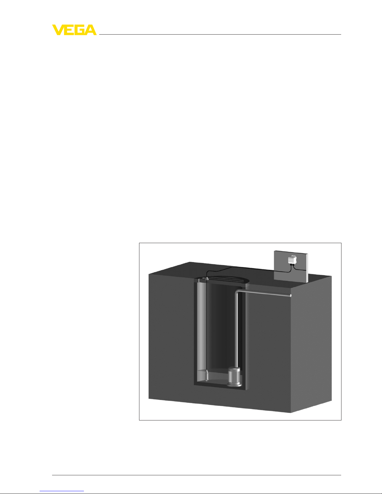
Fig.3:Mounting example:VEGAWELL 52 in a pump shaft with breather housing
VEGABOX 02
Suitability for the pro-
cess conditions
Mounting position
Pressure compensation
Mounting example
VEGAWELL 52 •4…20 mA11
4Mounting
35401-EN-111021

4.2Mounting steps with straining clamp
2
3
1
Fig.4:Straining clamp
1Suspension cable
2Suspension opening
3Clamping jaws
Mount VEGAWELL 52 with straining clamp as follows:
1Hang the straining clamp on a suitable wall hook
2Lower VEGAWELL 52 to the requested height
3Slide the clamping jaws upward and push the suspension cable
between them
4Hold the suspension cable,push the clamping jaws downward
and fix them with a light blow
Removal is carried out in reverse order.
12 VEGAWELL 52 •4…20 mA
4Mounting
35401-EN-111021

4.3Mounting steps with screwed connection
1
2
3
4
5
6
Fig.5:Threaded fitting
1Suspension cable
2Seal screw
3Cone bushing
4Seal cone
5Threaded fitting
6Seal
Mount VEGAWELL 52 with screwed connection as follows:
1Weld the welded socket into the vessel top
2Lower VEGAWELL 52 to the requested height by means on the
welded socket G1½Aor 1½NPT on the vessel side
3Insert the suspension cable from below into the open screwed
connection
4Slide the seal cone and the cone sleeve over the suspension
cable,fasten manually with the seal screw
5Screw the screwed connection into the socket,fasten with SW 30
and then fasten seal screw with SW 19
How to correct the height:
1Loosen seal screw with SW 19
2Slide seal cone and cone sleeve to the requested position on the
cable
3Fasten the seal screw
Removal is carried out in reverse order.
VEGAWELL 52 •4…20 mA13
4Mounting
35401-EN-111021
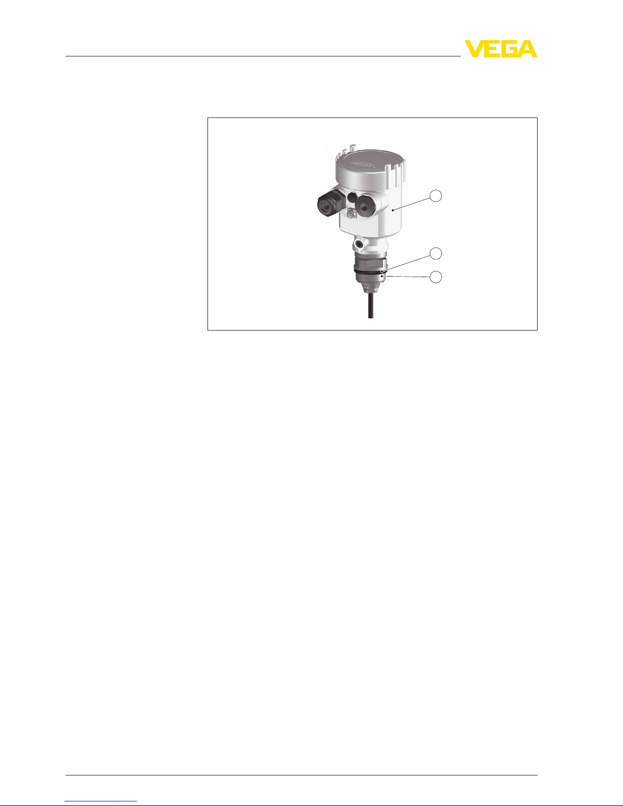
4.4Mounting steps with threaded connection or
housing
2
3
1
Fig.6:Plastic housing
1Housing
2Seal
3Thread
Mount VEGAWELL 52 as follows:
1Weld the welded socket G1½Aor 1½NPT to the vessel top
2Shift transmitter through the mounting boss
3Turn the thread with seal into the socket and tighten with SW 462)
Removal is carried out in reverse order.
Mount VEGAWELL 52 as follows:
1Fasten the mounting bracket at the suitable height on the basin
wall
2Lead the transmitter through the opening of the mounting bracket
and the counter nut
3Fasten counter nut with SW 46 on the thread
2)Seal the 1½NPT thread with teflon,hemp or a similar resistant material.
Mount into the vessel
Mounting into the basin
14 VEGAWELL 52 •4…20 mA
4Mounting
35401-EN-111021

5Connecting to power supply
5.1Preparing the connection
Generally connect the instrument only in the complete absence of line
voltage.
The instrument is equipped with an integrated overvoltage protection.
For additional protection of the signal circuit,we recommend further
external overvoltage arresters:
lType B63-48 (use with VEGAWELL 52 with plastic housing)or
lType ÜSB 62-36G.X(use in a separate housing)
Inhazardous areas you must take note of the respective regulations,
conformity and type approval certificates of the sensors and power
supply units.
Power supply and current signal are carried on the same two-wire
cable.The voltage supply range can differ depending on the
instrument version.
The data for power supply are specified in chapter "Technical data".
Provide a reliable separation between the supply circuit and the mains
circuits according to DIN VDE 0106 part 101.
VEGA power supply units VEGATRENN 149AEx,VEGASTAB 690,
VEGADIS 371 as well as all VEGAMETs meet this requirement.When
using one of these instruments,protection class III is ensured for
VEGAWELL 52.
Keep in mind the following additional factors that influence the
operating voltage:
lOutput voltage of the power supply unit can be lower under
nominal load (with a sensor current of 20.5mAor 22 mAin case of
fault message)
lInfluence of additional instruments in the circuit (see load values in
chapter "Technical data")
The instrument is connected with standard two-wire cable without
screen.If electromagnetic interference is expected which is above the
test values of EN 61326 for industrial areas,screened cable should be
used.
Use cable with round cross-section.Acable outer diameter of 5…9mm
(0.2…0.35 in)ensures the seal effect of the cable gland.If you are
using cable with a different diameter or cross-section,exchange the
seal or use a suitable cable gland.
Safety instructions
Take note of sa-
fety instructions
for Ex applica-
tions
Select power supply
Select connection cable
VEGAWELL 52 •4…20 mA15
5Connecting to power supply
35401-EN-111021
1
2
3
123456
123456
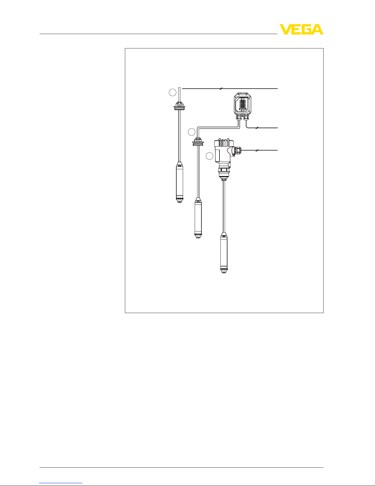
Fig.7:Connect VEGAWELL 52 to power supply
1Direct connection
2Connection via VEGABOX 02
3Connection via housing
If screened cable is necessary,connect the cable screen on both ends
to ground potential.In the plastic housing,in VEGABOX 02 or in
VEGADIS 12,the screen must be connected directly to the internal
ground terminal.The ground terminal outside on the housing must be
connected to the potential equalisation.
If potential equalisation currents are expected,the connection on the
processing side must be made via a ceramic capacitor (e.g.1nF,
1500 V). The low frequency potential equalisation currents are thus
suppressed,but the protective effect against high frequency interfer-
ence signals remains.
Cable screening and
grounding
16 VEGAWELL 52 •4…20 mA
5Connecting to power supply
35401-EN-111021

Warning:
Within galvanic plants as well as vessels with cathodic corrosion
protection there are considerable potential differences.Considerably
equalisation currents can be caused via the cable scrren when the
screen is earthed on both ends.To avoid this,the cable screen must
only connected to ground potential on one side of the switching
cabinet in such applications.The cable screen must not be connected
to the internal ground terminal in the sensor and the outer ground
terminal on the housing not to the potential equalisation!
Information:
The metallic parts of the instrument (antenna,transmitter,concentric
tube,etc.) are conductively connected with the inner and outer ground
terminal on the housing.This connection exists either as a direct
metallic contact or via the shielding of the special connection cable on
instruments with external electronics.You can find specifications on
the potential connections within the instrument in chapter "Technical
data".
Take note of the corresponding installation regulations for Ex
applications.
5.2Connection procedure
Proceed as follows:
1Wire the connection cable up to the connection compartment3)
2Connect the wire ends to the screw terminals according to the
wiring plan
Proceed as follows:
1Snap VEGABOX 02 onto the carrier rail or screw it to the mounting
plate
2Loosen the cover screws and remove the cover
3Push the cable into VEGABOX 02 through the cable entry
4Loosen the screws with a screwdriver
5Insert the wire ends into the open terminals according to the wiring
plan
6Tighten the screws with a screwdriver
7Check the hold of the wires in the terminals by lightly pulling on
them
8Tighten the compression nut of the cable entry.The seal ring must
completely encircle the cable
9Connect the supply cable according to steps 3to 8
3)The connection cable is already preconfectioned.After shortening the ca-
ble,fasten the type plate with support again to the cable.
Select connec-
tion cable for Ex
applications
Direct connection
Connection via
VEGABOX 02
VEGAWELL 52 •4…20 mA17
5Connecting to power supply
35401-EN-111021

10 Screw the housing cover on
The electrical connection is finished.
5.3Wiring plan
4
1
2
2
3
Fig.8:Wire assignment,suspension cable
1Blue (-): to power supply or to the processing system
2Brown (+): to power supply or to the processing system
3Shielding
4Breather capillaries with filter element
1
2
–
+
123456
123456
Fig.9:Wiring plan VEGABOX 02
1To power supply or the processing system
2Shielding4)
Wire number Wire colour/Polarity Terminal VEGABOX 02
1brown (+)1
2blue (-) 2
Shielding Ground
4)Connect screen to ground terminal.Connect ground terminal on the outside
of the housing as prescribed.The two terminals are galvanically connected.
Direct connection
Connection via
VEGABOX 02
18 VEGAWELL 52 •4…20 mA
5Connecting to power supply
35401-EN-111021

1
2
4
5
3
6
1
2
Fig.10:Wiring plan housing
1To power supply or the processing system
12
+
( ) (-)
3 4
+
( ) (-)
12
3
Fig.11:Wiring plan,VEGADIS 62
1To the sensor
2For power supply
3Coupling for the connection cable to the indicating and adjustment module
Wire number Wire colour/Polarity Terminal VEGADIS 62
1brown (+)1
2blue (-) 2
Shielding Ground
5.4Switch-on phase
After connecting VEGAWELL 52 to power supply or after a voltage
recurrence,the instrument carries out a self-check:
lInternal check of the electronics
l4…20 mAoutput jumps to the failure signal
Connection via housing
Connection via VEGA-
DIS 62
VEGAWELL 52 •4…20 mA19
5Connecting to power supply
35401-EN-111021

After the run-up period (specification see "Technical data"), the
instrument delivers an output signal of 4…20 mA.The value
corresponds to the actual level as well as the settings already carried
out,e.g.factory setting.
20 VEGAWELL 52 •4…20 mA
5Connecting to power supply
35401-EN-111021
Table of contents
Popular Transmitter manuals by other brands

Car and Driver
Car and Driver CAD-9900 user manual

Mighty Mule
Mighty Mule FM134 user guide

Teslink
Teslink WPT171AT Installation information for customers & installers

BANGGOOD
BANGGOOD MXT-5G8-S1 manual

Motorola
Motorola T505 - MOTOROKR - Speaker Phone instruction manual

Renkforce
Renkforce RF-BTR-200 operating instructions


