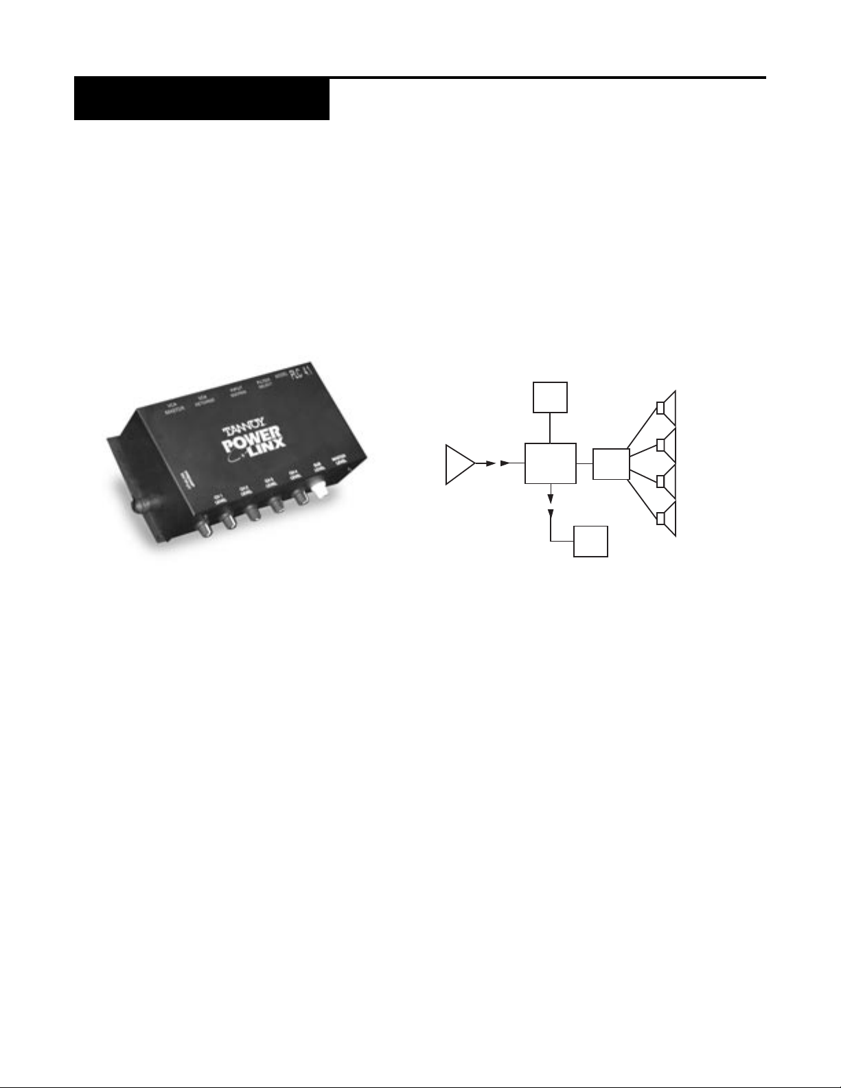
Tannoy PowerLinx Multi-channel Sound Reinforcement... User manual

OWNER/INSTALLER/OPERATOR'S MANUAL
PowerLinx Multi-channel Sound Reinforcement Systems
{

2
WARRANTY/DAMAGE CLAIMS
All Tannoy professional loudspeaker products are covered by a 5 year warranty for loudspeaker components and
one year for electronic components from the date of purchase subject to the absence of misuse, overload,
or accidental damage.
Claims will not be considered if the serial number has been altered or removed.
Work under warranty should only be carried out by a Tannoy Professional dealer or service agent.
This warranty in no way affects your statutory rights.
For further information please contact your service dealer or distributor in your area. If you cannot locate a distributor,
please contact Customer Services, Tannoy North America Inc. at the address given below.
DO NOT SHIP ANY PRODUCT TO TANNOY WITHOUT PRIOR AUTHORIZATION.
Our policy commits us to incorporating improvements to our products through continuous research and development.
Please confirm current specifications for critical applications with your supplier.
Tannoy North America Inc.
335 Gage Ave., Suite #1
Kitchener, ONTARIO CANADA
N2M 5E1
Tel: (519) 745-1158 } FAX: (519) 745-2364 } Toll Free Dealer Faxline: (800) 525-7081
For further information on our warranty policies,please refer to our website.
Our customer service dept. is available during normal office hours (EST) for questions regarding service, purchase,
installation or any other technical matters.
Installation of Tannoy products should be performed by an experienced contractor familiar with local
codes. Failure to properly install and secure heavy Tannoy equipment may cause a device to fall.
Tannoy cannot be responsible for damage or injury due to improperly installed equipment.
UNPACKING-DAMAGE CLAIMS
Each Tannoy product is inspected for damage and inventoried to insure that all accessories and packing materials are
included before sealing and shipping.
When unpacking equipment, take note of any damages to the cardboard container and carefully inspect your Tannoy
equipment for any impact in that area. Should you have any damage, immediately notify your carrier and our Tannoy
customer service dept. A return claim may be issued. You may be required to repack the equipment for pick-up by
your local carrier.
{

3
TABLE OF CONTENTS
WARRANTY/DAMAGE CLAIMS/UNPACKING
CONTENTS
INTRODUCTION
PLA305 5-Channel Amplifier
PLC4.1 Controller
PLM-4 Mixer w/Ducking
REMOTE LEVEL CONTROL
Wall-mount Potentiometer
PRODUCTS
PLA305 5-Channel Amplifier
PLC4.1 Controller
Description of Controls
Set-Up and Testing
System Commissioning w/remote
PLM-4 4-Channel Mixer/Preamplifier
Description of Controls
Installation and Set-Up
Technical Specifications
REMOTE LEVEL CONTROL
Wall-mount Potentiometer, Wiring
2
3
4
4
4
5
6
7
8
9
10
11,12
13
14
15
4
{

4
INTRODUCTION
PLA305 5-Channel Power Amplifier
Designed to mount directly into the cutout provided on one of our 110 series
subwoofers,the PLA305 is a powerful and versatile center of your multi-channel
sound reinforcement system. The 5 amplifiers (100 watts for the sub, 50 watts
each for the 4 full-range outputs) use ProBASH technology for great sound and
superb efficiency. ProBASH circuits track the audio waveform and provide a
dynamic DC voltage,on demand, to the class AB amplification stages. An auto-power
feature switches power on or off in response to the audio signal.
PLC4.1 Controller
Mounted directly to PLA305 amplifier the PLC4.1 Controller is the control center,
for audio signal pre-amplification, balancing, distribution and filtering. For a full
description of its flexibility and use see the PRODUCT section of this manual.,
Master remote volume control is possible with our remote control options (see the
REMOTE section of this manual). Individual channel remote volume control is
enabled with the installation of our VCA card (see your Tannoy dealer).
PLM-4 Mixer with Ducking
The PLM-4 has all the inputs needed for most commercial applications. It is
designed to provide a properly mixed and pre-amplified balanced audio feed to
the PLC4.1 Controller via a long-wire run. Power supply is by a 12V DC wall-wart.
For a complete description of its controls and functions, see the PRODUCT section
of this manual.
{
REMOTE VOLUME CONTROL
1) Wall-mount Potentiometer (25K ohm). Each multi-channel amplifier is shipped
Simple 3-wire connection to the PLC4.1.
NOTE: Overall master volume control is a standard function of the PLC4.1. Remote control of
individual channels requires the factory installed VCA card.
with one standard wall mount potentiometer.

5
POWERLINX PRODUCTS
PLA305 5-Channel Power Amplifier
The PLA305 amplifier resides in the 110 series subwoofer cabinet. All internal woofer connections are made for
you at the factory. Four external 50 watt full-range speaker connector sets are accessible on the front panel of the PLA305.
1) PREAMP INPUT
Accepts the supplied 30 cable from the PLC4.1. Audio signals from and power to the PLC4.1 are routed via this
cable. Note that the PLC4.1 module may be temporarily located remotely, with the 12 cable option,
to facilitate system set-up
2) SPEAKER OUTPUTS
Four separate 50 watt speaker-level outputs are provided. Each output should be limited to a minimum of 3 ohms
speaker load. Wire connections are made via spring-loaded push-and-release connectors (maximum wire size; 14
gauge). Your choice of plenum-rated speaker wire should be made with consideration for length of run and damping
characteristics. Be sure to observe consistent phasing of your full-range speakers and avoid shorting of
speaker wires.
3) POWER CORD
110VAC 60 Hz 5A. A standard 2-prong plug is provided. There is no power switch on the PLA305. Automatic power
on/off is made in the presence or absence of an audio signal.
1
2
3
{

6
POWERLINX PRODUCTS
FULL-RANGE
SPEAKERS
ACTIVE
110 SUB
110 SUB
W/S1-341
AMPLIFIER
PLC 4.1
REMOTE VOLUME (VCA)
(OPTIONAL)
STEREO SOURCE
LINE LEVEL
SUB-LOOP OUT
(LINE LEVEL)
2nd ZONE
SUBWOOFER
PLC4.1 Controller
The PLC4.1 Controller is designed to mount directly to the face the PLA305 amplifier panel. However, a 12
interconnect cable is available from your Tannoy dealer if a remote set-up of the PLC4.1 is required. All controls and
connectors on the PLA305 and PLC4.1 are accessible when the controller is mounted to the amplifier.
The PLC4.1 is ideally suited to receive a 2-channel, pre-amplified audio signal from the PLM-4 or other signal source via
a balanced wire run (Belden 8451, or equivalent). Each input may be commissioned to any combination of the 4 outputs.
Additional features of the PLC4.1 include:
} Switchable high-pass filtering for any output.
} Individual volume control for each speaker output (the subwoofer and SUB LOOP
OUTPUT volume share one control).
} VCA interfacing for remote master volume control. Multi-channel remote volume control is possible when our
optional VCA card is installed.
The following configurations are typical of the many systems possible with Power Linx:
} Subwoofer and four mono channels
} Subwoofer and two stereo pairs
} Subwoofer, stereo pair, and two mono channels
} Two subwoofers and two stereo pairs
} Full-range sub-line out, sending to a second similar system, effectively doubling the capabilities listed above.
Note that it is not necessary to use all four channels. Any speaker level output may be left unused.
Additionally, more than one speaker may be connected to each output and each channel can handle
{
loads down to 3 ohms.

7
POWERLINX PLC4.1 CONTROLLER
Description of Controls Rear
Front
Side
1
5
2
MR+10V 341
SUB
2
OUT
IN
8
7
6
45
2
13
13
24
L R
910
SUB
L R L R L R L R
L = Left Input
R = Right Input
DOWN = 80Hz Hi-Pass
UP = Full Frequency
1234
INPUT
LEFT
OUT
LOOP
SUB
INPUT
RIGHT
++ +
LINE LEVEL ONLY
3
4
6
7
89
1) CH1 through CH4 LEVEL Adjusts the level of each of 4 full range outputs which arerouted to the PLA305 amplifier.
2) SUB-LEVEL Adjusts the level of the subwoofer amplifier output, as well as the level of the sub-loop output
3) MASTER LEVEL Adjusts the overall level of all 5-speak er level outputs to the PLA305 amplifier, including
the line level output.
4) VCA MASTER Connections for use of a remote volume control. (See REMOTE.)
5) VCA RETURNS Individual channel connections for remote volume control when the optional VCA card is installed.
See your Tannoy dealer. (See REMOTE.)
6) INPUT MATRIX Assigns either left, right, both or neither of the two inputs to any of the five outputs. DIP switches
are used to switch the left or right signals IN or OUT for each channel. EXAMPLE: To enable both left and right inputs
to sum together for the subwoofer, switch DIP sw#1 and #2 to the down (IN) position. If any output is not to be used,
its 2 switches may be set up to the OUT position.
7) FILTER SELECT Allows selection of an 80 Hz high-pass filter to be added to any combination of the 4 outputs,
thereby reducing low frequency content in the selected channels.
8) LEFT and RIGHT INPUTS Balanced line-level inputs on the PLC4.1 Controller. Wire termination via Phoenix
connectors for tinned, bare wire leads, 18-24 gauge.
9) SUB LOOP OUT A line-level, full bandwidth balanced output for use with a second subwoofer or full range system.
Level control of this output is in concert with the SUB and MASTER levels..
{

8
Set-Up and Testing
POWERLINX PLC4.1 CONTROLLER
Before applying power to the system, insure that all audio connections are properly
terminated and all level controls including the control room feeds are set to minimum.
Once your system is fully wired to a sound source and speakers, a careful balancing of all levels is necessary to provide
pleasing sound levels, adequate audio headroom, and system protection from excessive volume or overdriving.
System Commisioning Procedure-
Unless fitted with a remote volume control, all level adjustments (excepting the control room feeds) are performed on
the PLC4.1 Controller.
1) Set all level controls to minimum. Remove security covers and set all FILTER SELECT switches to FULL FREQUENCY.
2) Plug the PLA4.1 into a 110vac wall output.
3) Set MASTER LEVEL control to mid position.
4) Start the music source and adjust audio feeds to mid position.
5) Adjust CH 1 through CH 4 LEVEL controls to their desired operating levels. If satisfactory levels cannot be
achieved, increase the MASTER LEVEL control and readjust the channel levels if necessary.
6) Switch FILTER SELECT switches to their DOWN position (80 Hz high-pass) for those speakers that will be used
in conjunction with a subwoofer, or cannot reproduce frequencies below 80 Hz.
7) Adjust the SUB LEVEL control until the subwoofer level is balanced with its main speakers.
Note that the use of high-pass filters will increase the overall system headroom by several dB.
8) Once all levels are satisfactory, reinstall the security covers on the PLC4.1.
{

{
9
POWERLINX PLC4.1 CONTROLLER
System Commisioning for Remote Volume Controls Procedure-
Systems fitted with wall mount volume control require careful commissioning to ensure that safe levels cannot be
exceeded at any wall control panel. The optional remote controls can only attenuate levels downward from the maximum
levels set on the PLC4.1 Controller.
1) Set all level controls on the PLC4.1 to minimum.
2) Set wall panel control(s) to minimum.
3) Set all FILTER SELECT switches to FULL FREQUENCY.
4) Plug the PLA305 amplifier into a 110vac wall outlet.
5) Set all wall panel controls to maximum.
6) Adjust sub level and master level wall panel controls to maximum.
7) Adjust MASTER LEVEL control to its mid position.
8) Select a channel (or zone) where the highest sound levels will be required.
9) Start the music source. Feed levels should be at mid position.
10) Carefully adjust the selected channel's LEVEL control to the desired maximum safe level. If an adequate level
cannot be achieved, check the signal source level and readjust if necessary
.
11) If an adequate level still cannot be achieved, raise the MASTER LEVEL to a higher position. Readjust the channel
LEVEL to achieve the desired volume.
12) Set the three remaining channel LEVEL controls to their appropriate levels without adjusting the
MASTER LEVEL control.
13) Once the levels on the PLC4.1 have been set, all operator level changes will be made at the remote wall
control panel.
14) Switch FILTER SELECT switches to their DOWN position as required.
15) Adjust the SUB LEVEL control for a subwoofer sound level that is complementary with its associated main speakers.
16) Reinstall the security covers on the PLC4.1.

10
PLM-4 4 CHANNEL MIXER/PREAMPLIFIER with DUCKING
Designed as the input control center for your music system, or a stand-alone mixer, the free-standing PLM-4 is usually
installed remotely in a control room and interfaced to the PLC4.1 Controller by a long-wire run, either balanced XLR to
the PLC4.1B (recommended for lowest noise) or unbalanced RCA to a PLC4.1. Low current power is provided by a
supplied 12VDC wall wart. Additional PLM-4s may be link ed for more inputs.
Some of the many features of the PLM-4 include:
}A balanced XLR microphone input
}Three RCA stereo line inputs
}Balanced (XLR) and unbalanced (RCA) outputs
}Three position ducking (mic-over-music) switch: Mute/Dim/None
}Independent volume for all the input sources
}Up to 3 PLM-4s may be linked together for more inputs
}Master Volume, Bass, and Treble controls
}Ground lift switch
}Half rack size
}Operates anywhere on 9 to 15 volts, DC or AC. Supplied wall wart supply.
{

11
POWERLINX PLM-4 MIXER/PREAMPLIFIER
Description of Controls
1) SENSITIVITY TRIM (SENS.) Sets the microphone trigger level when DIM or MUTE is selected.
2) DUCKING This switch selects one of three options that determine how microphone announcements
affect the music level:
NONE -No ducking
DIM - Automatic 10 dB music level reduction while speaking into the microphone.
MUTE - Automatically shuts the music off when speaking into the microphone.
3) MIC Adjusts the microphone level (equally distributed between left and right outputs).
Ducking does not affect this level.
4) STEREO 1 STEREO 3 Adjusts the level of the STEREO RCA inputs. These inputs are suitable for CD players,
tuners, TVs, VCR audio, etc.
5) BASS Over all adjustment of low frequency levels.
6) TREBLE Over all adjustment of high frequency levels.
7) MASTER Adjusts overall level of all the mixed audio sources. Adjust to provide a suitable signal level to
the PLC4.1 controller or other following amplifier. Unity gain of the mixer is provided when STEREO input
and MASTER output levels are at 12 o'clock.
POWER
MIC STEREO 1 STEREO 2 STEREO 3 BASS TREBLE MASTER
10
6
8
4
2
0
+12
+3
+6
-3
-6
0
-12 +12
+3
+6
-3
-6
0
-12
MUTE DIMNONE
SENS.
6
8
4
2
010 10
64
2
0
8
10
6
8
4
2
010
6
8
4
2
0
MIC
MODEL
PLM-4 MIXER
-
-
DUCKING
8
1
2 3 5 6 74
{

12
POWERLINX PLM-4 MIXER/PREAMPLIFIER
Description of Controls
1) LINE 1 - 3 INPUTS Stereo, line-level RCA inputs for tape decks, CD players, tuners, etc.
2) MICROPHONE (MIC) INPUT Balanced XLR connector suitable for almost any kind of microphone, balanced
or unbalanced. The microphone signal is evenly distributed to the left and right outputs. Pin-out is: 1 (GND), 2 (HI), 3 (LO).
3) OUTPUTS The PLM-4 offers both unbalanced RCA connectors for short wire runs to other unbalanced equipment
and balanced XLR output connectors for longer wire runs to other balanced input devices such as the PLC4.1.
Both outputs may be used simultaneously if required. XLR pin-out is: 1 (GND), 2 (HI), 3 (LO).
4) LINK CONNECTORS Up to 3 PLM-4s may be daisy chained using 5-pin DIN cables via the LINK IN
and OUT connectors.
Connect the LINK OUT of the master unit to the LINK IN of the #2 unit. Connect the LINK OUT of the #2 unit to
the LINK IN of the #3 unit.
Note the following when interconnecting PLM-4s:
} Up to 9 stereo line inputs and up to 3 microphone inputs are possible.
} Power need be connected only to the master unit.
} BASS and TREBLE controls affect inputs on that unit only.
} The MASTER level on the master unit affects all inputs.
} MASTER levels on units #2 and #3 should be set and retained (5 to 7 recommended).
} The DUCKING switch and SENS. trim govern the ducking function on that unit only.
However:
} If a microphone signal is high enough to trigger ducking, at any unit, all sources to all units will be ducked
or muted at the main output of the master unit.
5) ON/OFF SWITCH This switch is located on the rear panel to prevent accidental switching.
6) GROUND (GND) LIFT SWITCH This switch isolates the signal grounds from the chassis and is switched
for least hum or buzz in the output. Note that hum or buzz may have many other possible causes.
7) POWER SOCKET Receives the plug from the supplied 12VDC power supply. Any AC or DC voltage supply
may be used. Power requirements are 9 to 15Vac or DC >100ma.
LEFT RIGHT MICLINE 2 LINE 1
ON
OFF
9 - 15V AC/DC 1OOmA
L
R
LINE 3
LIFT
GND
+
LINK
INOUT L
R
L
R
OUTPUTS INPUTS
1
2
3
4
5
6
{

13
POWERLINX PLM-4 MIXER/PREAMPLIFIER
Installation
Before applying power to the system, insure that all audio connections are properly
terminated and all level controls are set to minimum.
For optimum performance,the PLM-4 should be connected to the PowerLinx controller through its balanced XLR output
to the controller's balanced Phoenix-type inputs (Belden 82761 or equivalent). As a stand-alone unit the PLM-4 may be
connected to the balanced or unbalanced input of an audio system amplifier.
A microphone with an on/off switch is recommended so it can be left in the "Off" position when not in use for
announcements. In this way, background noise in the vicinity of the microphone won't be heard through the system and
won't trigger the ducking feature. To a void feedback, be sure not to place your microphone too close to your audio sys-
tem's loudspeakers, and use shielded cables for all audio connections.
SET-UP
1) Plug the AC adaptor into the +9-15V AC/DC input on the rear of the PLM-4 and then into a power outlet.
Turn on the power to the PLM-4 and your other equipment.
2) Set the MASTER control to about mid position.
3) Adjust the STEREO 1, 2, and 3level controls on the PLM-4 for your music playback source(s) to comfortable
listening levels.
4) Set your MIC level control to a suitable level for announcements.
5) Select your preferred ducking setting. The three-position DUCKING switch is located below the microphone
level control. You can select "NONE" for no ducking, "DIM" for an automatic 10 dB level reduction of the back
ground music while speaking into the microphone or "MUTE" to shut the music off completely while you're,
speaking into the microphone..
6) If you chose DIM or MUTE, adjust the SENS. trim with a small screwdriver. Set it so that speaking into the
microphone in a normal voice triggers ducking but whispering or rustling papers nearby doesn't. Now if you,
wish to make an announcement, the background music volume will be reduced while you speak, and will
automatically increase to its previous level after the announcement ends.
7) The MASTER level control should now be adjusted to provide a suitable level to your PLC4.1 or other following
audio equipment. This level should be as high as possible for best noise characteristics but not so high as to
overdrive the following inputs. Usually a position of 5 to 7 is optimum.
8) If any hum or buzz is noted in your audio systems output, try switching the GND LIFT switch. Note that ground
loops or other interferences may occur at any point in the chain of your equipment.
Since the PLM-4 is an end-user adjustable device the mix may be readjusted at any time. However the MASTER setting,
should be carefully made and retained as it has a direct effect on the headroom, audio quality and system protection of,
the PLA305 and its associated loudspeakers.
{

14
POWERLINX PLM-4 MIXER/PREAMPLIFIER
Technical Specifications
INPUTS:
} 3X Stereo line, 5k ohms RCA. Maximum input level: +30 dBu
}1X Balanced XLR Mic input, 2k ohms. Maximum input level:+1 dBu. Maximum gain to unbalanced output:
75 dB. XLR pin-out is: 1 (GND), 2 (HI), 3 (LO).
MAXIMUM GAIN:
}30 dB at output, all levels at maximum.
}Unity gain when input and MASTER controls are at 50% rotation.
EQUIVALENT INPUT NOISE:
}-126 dBu, unweighted 20 Hz to 20 kHz.
OUTPUTS:
}Impedance: 100 ohms, unbalanced. 200 ohms, balanced.
}Maximum output level: +19 dBu, unbalanced. +25 dBu, balanced.
}Recommended load impedance: >2.5k ohms. Lesser impedance loads will be tolerated but maximum output
levels will be reduced.
}Connectors: RCA (unbalanced). XLR (balanced) +6 dB over RCA levels.
XLR Pin-out:1 (GND), 2 (HI), 3 (LO).
LINKS (for more PLM-4s) via 5-pin DIN
GENERAL:
}Frequency response: +0, -1 dB from 20 Hz to 20 kHz.
}Output noise:< -80 dBu from 20 Hz to 20 kHz with input and MASTER controls at 12 o'clock and inputs shorted.
}Distortion: < .02% THD at maximum rated output.
}Equalization: Bass +/-14 dB @ 40 Hz. Treble +/- 14 dB @ 18 kHz.
}Dimensions: 1.73 H x 8.56 W x 5 D. Rack mountable with kit from Tannoy. Painted steel chassis.
}Power requirement: 12VDC, 100ma at 4 watts. Adaptor supplied. A 230V AC adaptor is also available.
{

15
REMOTE LEVEL CONTROL
25K Linear Potentiometer
All PLC4.1 Controllers will accept this option for remote control of over all (master) volume control. The potentiometer is
typically installed in a single-gang electrical box with a blank cover panel drilled to accept the control. Simple 3-wire
22ga, or equivalent, interconnection. Wiring is as follows:
25K Linear Potentiometer (For PLC4.1 w/factory-installed VCA card option)
Individual channel (1, 2, 3, 4 and/or SUB) remote volume control is possible with the factory-option VCA card. (See your
Tannoy dealer). One or more potentiometers may control any PLC4.1 output(s) in any combination. This is achieved by
wiring the Master Return connection from the potentiometer(s) to the VCA RETURNS connector (one or more pins) for
the channel(s) you wish to control.
EXAMPLE: Channels 1 and 2 are feeding a stereo signal to zone #1 you wish to control. Channel 3 is feeding a mono
signal to zone #2 you wish to control separately. Wire the Master Return connection from zone #1's potentiometer to
VCA RETURN 1 and 2connector pins. Wire the Master Return connection from zone #2's potentiometer to the
VCA RETURN 3 connector pin. The + 10V and GROUND connections are common to all used potentiometers.
Rear
of Pot
+ Voltage
Master Return
Ground
PLC4.1 PowerLinx Controller
+ 10V
Master Return
Ground
Rear
of Pot
To +10V
PLC4.1 PowerLinx Controller
1234
Sub
Channels
ZONE #1
Rear
of Pot
To Channel 3
To Channels 1 & 2
To Ground
ZONE #2
+10V MR
{

Tannoy North America Inc. 335 Gage Avenue, Suite #1 Kitchener, Ontario Canada N2M 5E1
Tel: 519-745-1158 Fax: 519-745-2364 E-mail: [email protected]
www.tannoy.com
MC-I180703
{
This manual suits for next models
1
Table of contents
Other Tannoy Music Mixer manuals