Tannoy TMA120 User manual

TANNOY LIMITED, PROFESSIONAL DIVISION, COATBRIDGE, ML5 4TF. SCOTLAND
TELEPHONE: +44 (0) 1236 420199 FAX: +44 (0) 1236 428230 E-MAIL: prosales@tannoy.com
A MEMBER OF THE TGI PLC GROUP OF COMPANIES
TMA120
OPERATING INSTRUCTIONS
TABLE OF CONTENTS
Front Panel Features
Rear Panel Features
Modifications
Applications
Specifications
Block Diagram
Warranty Statement
Appendices
pg. 2
pg. 3
pg. 5
pg. 6
pg. 10
pg. 10
pg. 11
pg. 12
INTRODUCTION
The TMA120 commercial mixer/amplifier combines a versatile 6-
input mic/line mixer with 120 Watt amplification. Mixing
functions include mic/line/telephone inputs, selectable automatic
& manual channel muting, channel priority assignment, remote
level control, tone control, a built-in compressor, an internal
chime, phantom power, and extensive output patching. The
amplifier includes an output transformer, and provides rated
power into direct or distributed speaker systems.
TMA120 features include:
• integrated mixer, power amplifier, and output transformer
• five electronically balanced microphone/line input channels
• one transformer balanced microphone/line/tel input channel
• rear panel trim control & pad switch on each input channel
• +24 Volt phantom power selectable on each input channel
• input isolation transformer option on mic/line input channels
• automatic muting of selected channels (-10, -20, or -40dB)
• automatic muting triggered by selected "priority" channels
• manual muting of selected channels (-10, -20, or -40dB)
• manual muting triggered from remote contact closures
• remote control of master level via rear panel terminals
• integral output compressor with rear panel threshold control
• recessed treble & bass controls plus "loudness" & "low-cut"
• two insert points for signal processing and remote control
• two line-outs and one stack-in for system interconnections
• 120 Watts into direct or distributed systems
• front panel indicators for power, fault, signal, and peak
• internal 'pre-announcement' chime tone with level control
• input/output connections provided on barrier strip terminals
• integral security cover and removable rack-wing/handles
• covered by two year warranty
• marked, UL and C-UL (UL Canada) listed

2
FRONT PANEL FEATURES
Level (Channels 1~6): These controls adjust the
amount of signal sent from the individual input
channels to the mixer output. Optimum Level setting
is near the 12 o'clock position (unity gain).
Level (Master): This control adjusts the amount of
signal sent from the mixer output to the amplifier
input. The Master Level control is used to adjust the
overall volume of the system.
Low Cut: This switch inserts a low cut filter at the
amplifier input.
Loudness Contour: This switch inserts a loudness
filter at the mixer output (+6dB @ 100Hz & +4dB @
10kHz). The Loudness filter provides tonal
compensation when operating with low-level music
signals.
Tone Control: This switch enables the Bass &
Treble controls.
Bass: This screwdriver control adjusts the low-
frequencies ("Bass") at the mixer output (±10dB @
100Hz).
Treble: This screwdriver control adjusts the high-
frequencies ("Treble") at the mixer output (±10dB @
10kHz).
Peak Indicator: This red LED flashes when signal
levels at the amplifier output have reached
maximum. Occasional flashes of the Peak Indicator
are acceptable, however, a continuously lit LED may
indicate an excessive level setting.
Signal Indicator: This yellow LED remains lit when
signal is present at the amplifier output.
Fault Indicator: This red LED lights to indicate fault
conditions due to overheating, DC offset voltage, or
failure of low-voltage power. The Fault Indicator will
light for 3-5 seconds at turn-on, and then go off if no
fault is detected. Some faults (such as overheating)
will correct themselves when the unit has been
turned off awhile. If the Fault Indicator remains lit
when the unit is turned back on, contact your local
dealer.
On Indicator: This green LED remains lit when AC
power is applied to the unit.
Power Switch: This switch applies AC power to the
unit.

3
REAR PANEL FEATURES
Power Entrance: This receptacle accepts a 3-
prong AC power cord. WARNING: DO NOT REMOVE OR
DEFEAT THE GROUND PRONG, AS THIS CONSTITUTES A
SHOCK HAZARD. The removable lower portion of the
receptacle holds the AC fuse. NOTE: See AC Fuse
on page 6 for replacement by qualified personnel. A
chassis ground post is provided (next to the
receptacle) for system grounding.
Output Selector: This switch selects either direct
output or transformer coupled output from the
amplifier. The direct output is from the 4terminal.
Output Terminals: These screw terminals provide
connection for speaker loads (4, 8, 25V, 50V,
70V, or 100V) at the amplifier output. WARNING: THE
LOUDSPEAKER OUTPUTS POSE A RISK OF HAZARDOUS
ENERGY. LOUDSPEAKER CONNECTIONS MUST BE MADE
PROPERLY. THE OUTPUT TERMINAL COVER MUST BE
INSTALLED WHEN THE DEVICE IS ENERGIZED.
Chime Level: This control adjusts the volume level
of the chime tone (see Mute/Chime on next page).
To turn the chime tone off completely, set this control
to the fully counter-clockwise position.
Send/Return: This 3-conductor TRS 1/4" Phone
jack provides an insert point for signal processing or
remote control devices. It is wired with Tip as send,
Ring as return, and Sleeve as ground. Send/Return
is after Stacking In, Loudness, & Tone, but before
Compressor, Master Level, & Low Cut. Send/Return
is a switching jack, which interrupts the signal flow
only when a plug is inserted.
Line Out: This RCA phono jack provides an
unbalanced line-level output from the mixer. Line
Out is after Stacking In, Loudness, Tone,
Compressor, & Master Level, but before Low Cut.
Rec Out: This RCA phono jack provides an
unbalanced line-level output from the mixer. Rec
Out is after Stacking In, but before Loudness, Tone,
Compressor, Master Level, & Low Cut.
Pre Out: This RCA phono jack provides an
unbalanced line-level output from the mixer. Pre Out
is after Stacking In, Loudness, & Tone, but before
Compressor, Master Level, & Low Cut. Pre Out and
Amp In may be used together as an insert point for
signal processing or remote control devices.
Remove jumper before connecting devices. To
connect Pre Out to both Amp In and an external
device, a parallel (‘Y’) cable must be used.
Amp In: This RCA phono jack provides an
unbalanced line-level input to the amplifier. Amp In
is after Stacking In, Loudness, & Tone, but before
Compressor, Master Level, & Low Cut. Pre Out and
Amp In may be used together as an insert point for
signal processing or remote control devices.
Remove jumper before connecting devices.
Compressor: This control adjusts the threshold
level at which the internal compressor circuit is
activated. The internal compressor has a fixed
compression ratio of 4:1, and is used to reduce
peaks in output signal level, as well as to moderate
volume differences between loud and soft signals.
Auto Mute: This control adjusts the threshold level
at which signals from "priority" channels will
automatically trigger muting of selected non-priority
channels (see Assignment & Priority below).

4
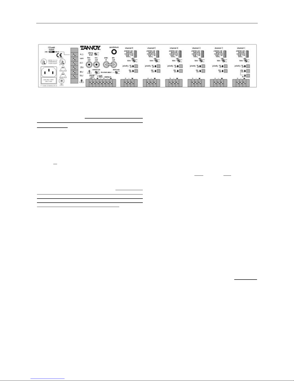
Remote Level: These two screw terminals (plus "ý")
provide remote volume control of the master level.
An internal voltage controlled amplifier (VCA) allows
remote control from up to 2000 ft (600m) away,
using any 5k~50klinear taper potentiometer and/or
switch to provide adjustment and/or muting of the
master level. Potentiometers are wired with high-
side to "+10V", low-side to "ý", and wiper to "C".
Switches simply connect (or disconnect) "+10V" to
"C", and do not require a ground (‘ý’) connection.
NOTE: The factory installed jumper (between
"+10V" & "C") must be in place when a remote
control is not being used.
Mute/Chime: This screw terminal (plus "ý") allows
manual muting of any selected channels, via an
external switch or contact closure (see Assignment &
Priority below). When the Chime Level control is
turned up (on), a pre-announcement chime tone will
also be activated by the switch or contact closure.
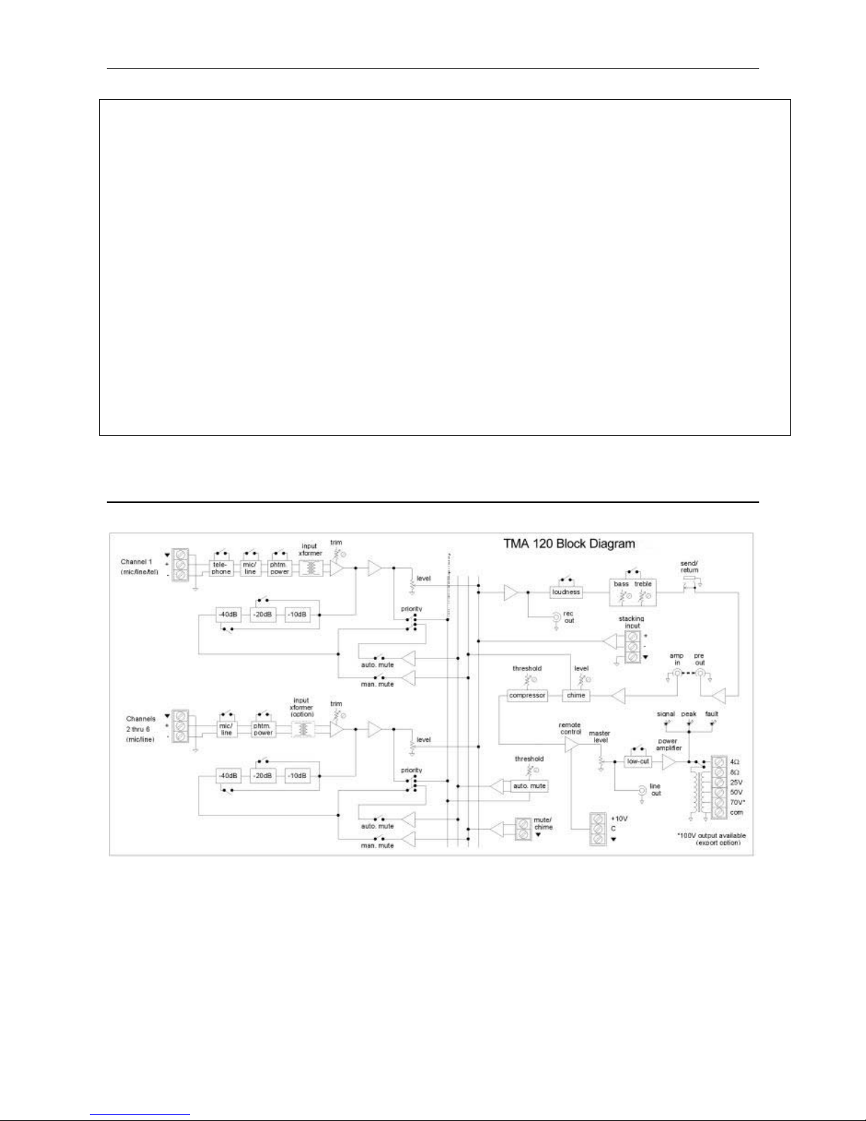
Stacking In: These screw terminals provide a
balanced line-level input to the mix bus, for input
expansion. Stacking In is before Loudness, Tone,
Compressor, Master Level, & Low Cut. For
unbalanced input, wire high to (+) and ground to
both (-) & (ý).
Assignment: These five DIP switches are used to
assign specific functions to the individual channels.
To assign a function, move the respective switch to
the left. Phantom Pwr assigns +24 Volts DC
phantom power to the channel input, for powering
condenser microphones. CAUTION: TO AVOID
DAMAGE TO EQUIPMENT, ASSIGN PHANTOM POWER ONLY
ON CHANNELS WHICH ARE SELECTED FOR 'MIC' INPUT
AND WHICH REQUIRE PHANTOM POWER. Auto Mute
assigns a (non-priority) channel to be muted
whenever signal is present in any "priority" channel.
Manual Mute assigns a channel to be muted
whenever the Mute/Chime terminals are shorted
together via a switch or contact closure. Mute Level
assigns the amount of muting (-10dB, -20dB, or -
40dB) which is applied to a channel, when triggered
by either Auto Mute or Manual Mute. NOTE: -10dB
muting will occur when both switches are to the right.
-40dB muting will occur when both switches are to
the left.
Trim: This control adjusts the input gain of the
channel, to compensate for various input signal
levels. Once the Line/Mic switch has been set to the
proper position (see Line/Mic below), the Trim
control should be adjusted so that peaks in signal
level do not cause distortion at the channel input.
Priority: This switch assigns a channel to "priority".
When signal is present in a "priority" channel, any
(non-priority) channels which are assigned to Auto
Mute will be muted by their selected amount. NOTE:
A "priority" channel cannot be auto muted by another
"priority" channel, but a "priority" channel can be
manual muted.
Line/Mic: This switch selects the proper impedance
and gain for either microphone or line-level input
signals. Depress the switch for line-level input.
Release the switch for microphone input. On
Channel 1, the Tel switch (see Tel below) must be
released for the Line/Mic switch to operate.
Tel (Channel 1 only): This switch selects the
proper impedance and gain for input from 600 ohm
sources. The input for Channel 1 includes an
isolation transformer, which allows connection to
most telephone system audio ports.
Inputs: These screw terminals provide a balanced
input connection for the channel. For unbalanced
input, wire high to (+) and ground to both (-) & (ý).
The input for Channel 1 includes an isolation
transformer.

5
MODIFICATIONS
CAUTION: THE FOLLOWING INFORMATION IS FOR USE BY QUALIFIED INSTALLATION/SERVICE PERSONNEL.
Removable Rack-Handles: The TMA120 has removable rack-handles. To remove the rack-handles: 1)
Remove the two screws from the side of each rack-handle. 2) Remove the rack-handles. 3) Replace the
mounting screws in the sides of the chassis.
Security Cover: The TMA120 includes a removable front panel security cover. A hole in the security cover
provides access only to the power switch. To remove the security cover: 1) Using a 3mm hex wrench,
loosen the two captive security cover mounting screws. 2) Remove the security cover.
WARNING: TO REDUCE THE RISK OF SHOCK, DISCONNECT ALL POWER FROM THE UNIT BEFORE MAKING ANY INTERNAL
MODIFICATIONS OR EXTERNAL FIELD WIRING CONNECTIONS.
230V/115V AC Operation: The TMA120 may be converted to 115V operation for use in other countries. To
convert to 115V operation: 1) Remove the fuse holder compartment from the lower portion of the rear panel
AC Power Cord receptacle. 2) Replace the fuse in the fuse clip with the same type and appropriate value
fuse (see table below). 3) Replace the fuse holder compartment.
115VAC FUSE VALUE
6A NB
230VAC FUSE VALUE
3A NB
USE ONLY WITH
250V FUSE
4) Select the correct position on the Power Selector Switch. The Power Selector is recessed into the
underside of the chassis, near the AC Power Cord receptacle.
bottom panel
rear panel
115V 230V

6
APPLICATIONS
Commercial / Industrial Paging System
This application shows a TMA120 being used in a commercial/industrial paging system. Channel #1 is set for
input from the telephone paging line, and is assigned both as a priority channel and manual muting of -20dB.
Channel #2 is set for input from the security paging microphone, which also has a push-to-talk switch wired to
the Mute/Chime terminals of the TMA120. Channel #3 is set for input from the line-level background music
source, and is assigned manual and auto muting of -20dB. Therefore, telephone paging will automatically
mute only the background music, whereas, security paging will manually mute both the background music and
the telephone paging. The TMA120 is set for 'xfmr' output and is connected to a 70V/100V distributed
speaker system.
WARNING: THE ABOVE DIAGRAM SHOWS THE OUTPUT TERMINAL COVER REMOVED FOR CLARITY ONLY. THE COVER
MUST BE INSTALLED WHEN THE UNIT IS ENERGIZED.

7
APPLICATIONS
Church Sound Reinforcement System
This application shows a TMA120 being used in a church sound reinforcement system. Channels #1~5 are
set for input from the various microphones. Channel #6 is set for input from the tape deck (playback), which is
also connected to Rec Out of the TMA120 (recording). If additional inputs are required, an auxiliary mixer
(such as another TMA120) may be connected to the Stacking In terminals of the TMA120. The mixer
amplifier is set for 'direct' (4Ω) output and is connected (in parallel) to the two 8Ωspeaker cabinets.
WARNING: THE ABOVE DIAGRAM SHOWS THE OUTPUT TERMINAL COVER REMOVED FOR CLARITY ONLY. THE COVER
MUST BE INSTALLED WHEN THE UNIT IS ENERGIZED.

8
APPLICATIONS
Retail Store Paging System
This application shows two TMA120s being used in a retail store paging system.
Channel #1 of the store TMA120 is set for input from the telephone paging line. The telephone system also
provides a paging contact closure which is wired to the Mute/Chime terminals. Channel #2 is set for input
from the line-level digital message repeater, and is assigned both as a priority channel and manual muting of -
20dB. Channel #3 is set for input from the line-level background music source, and is assigned manual and
auto muting of -10dB.
Channel #1 of the warehouse TMA120 is set for input from the warehouse paging microphone, which also has
a push-to-talk switch wired to the Mute/Chime terminals. Channel #6 is set for input from the line-level Pre
Out of the store TMA120 and is assigned manual muting of -40dB. Therefore, the digital message repeater
will automatically mute only the background music (-10dB), whereas, telephone paging will manually mute
both the background music (-10dB) and the digital message repeater (-20dB). These combined signals from
the store TMA120 are then fed to the TMA120 in the warehouse, where they are manually muted by any
warehouse paging (-40dB). Potentiometers are wired to the Remote Level terminals of both mixers, providing
remote control of store and warehouse levels. They are both set for 'xfmr' output and are connected to
70V/100V distributed speaker systems.
WARNING: THE ABOVE DIAGRAM SHOWS THE OUTPUT TERMINAL COVER REMOVED FOR CLARITY ONLY. THE COVER
MUST BE INSTALLED WHEN THE UNIT IS ENERGIZED.

9
APPLICATIONS
Multi-Floor Office/Hospital Paging System
This application shows three TMA120s being used in a multi-floor office/hospital paging system. An all-call
paging microphone and a background music source are distributed independently to the three TMA120s.
Channel #1 of each TMA120 is set for input from line-level all-call paging, and is assigned as a priority
channel. Channel #2 of each TMA120 is set for input from the respective floor paging microphone, and is
assigned auto muting of -40dB. The push-to-talk switch of each floor paging microphone is wired to the
Mute/Chime terminals of the respective TMA120. Channel #3 of each TMA120 is set for input from line-level
background music, and is assigned manual and auto muting of -20dB. Therefore, local paging will manually
mute the background music only on that floor (-20dB), whereas, all-call paging will automatically mute
background music (-20dB) and local paging (-40dB) on all floors. The TMA120s are set for 'xfmr' output and
are connected to 70V/100V distributed speaker systems for each floor.
WARNING: THE ABOVE DIAGRAM SHOWS THE OUTPUT TERMINAL COVER REMOVED FOR CLARITY ONLY. THE COVER
MUST BE INSTALLED WHEN THE UNIT IS ENERGIZED.

10
SPECIFICATIONS
Output Power: 120 Watts Input Impedance / Sensitivity
Power Bandwidth (THD < 0.4%): mic inputs 6kΩ/ -77dBu (110µV)
direct output 20Hz~20kHz line inputs 15kΩ/ -37dBu (14mV)
transformer output 50Hz~20kHz telephone inputs 600Ω/-60dBu (775µV)
Frequency Response (+0/-1.5dB): amplifier input 10kΩ/ +4dBu (1.2V)
direct output 20Hz~20kHz stacking input 20kΩ/ -8dBu (300mV)
transformer output 50Hz~20kHz patch/return input 10kΩ/ -8dBu (300mV)
Total Harmonic Distortion (1kHz @ rated power):< 0.2% Output Impedance / Level:
Output Regulation (no load to full load) < 0.5dB preamp output & line output 200Ω/ +4dBu (1.2V)
Equivalent Input Noise (mic in, 150Ωtermination):< 0.2% record output 200Ω/ +4dBu (1.2V)
Signal-to-Noise Ratio (20Hz-20kHz @ rated power):patch/send output 50Ω/ -8dBu (300mV)
line inputs 78dB Amplifier Output Impedance / Level:
telephone inputs 78dB 4 Ω/ 22V 20.8 Ω/ 50V
master level off 98dB 8 Ω/ 31V 40.8 Ω/ 70V
Compressor:
5.2 Ω/ 25V 83.3 Ω/ 100V
attack time < 1mSecond Power Consumption (120VAC 60Hz / 240VAC 50Hz):
release time > 1 Second Weight 12 kg (26.45 lbs)
compression ratio 4 : 1 Dimensions (includes rack/handles & feet):
threshold adjust range 15dB height (two rack spaces) 93.5mm/3.68"
width 482mm/19"
depth 364mm/14.33"
BLOCK DIAGRAM

Pa
g
e 11 of 24
WARRANTY
No maintenance of the TMA120 mixer amplifier is necessary.
All Tannoy electronics are guaranteed for a period of two years from the date of manufacture, subject to the
absence of, or evidence of, misuse, overload or accidental damage.
For further information please contact your dealer, or the distributor in your country. The best way to do this is
through the Tannoy website at www.tannoy.com However, if you cannot locate your local distributor, please
contact:
Customer Services
Tannoy Limited, Professional Division
Rosehall Industrial Estate
Coatbridge
Strathclyde ML5 4TF
SCOTLAND
Telephone 01236 420199 (UK) +44 1236 420199 (International)
Fax 01236 428230 (UK) +44 1236 428230 (International)
e-mail service@tannoy.com
DO NOT SHIP ANY PRODUCT TO TANNOY WITHOUT PREVIOUS AUTHORISATION.
This warranty in no way affects your statutory rights.
Other manuals for TMA120
1
Table of contents
Other Tannoy Music Mixer manuals