An Evaluation System for the TSL2550 Ambient Light Sensor
Plugging the motherboard into an active RS232 port (supporting RTS and DTR) will power the mother
and daughter boards. No external power is required unless SMBus devices requiring more than a
couple milliamps are attached to the 5-pin SMBus headers (also on the motherboard), or if the
onboard SX microcontroller is in debug mode or is being programmed.
To provide more power (
not to exceed 100 ma
) to the motherboard, an external supply can be
connected to the DB9 as follows:
1. Pins 4
and
7: +6 to +7.5VDC. (Note: Connect both pins.)
t
2. Pin 5: Ground.
To provide more power to the motherboard
and communicate wi h a PC at the same time
, an adapter
will have to be made incorporating the above connections in a DB9 male plug, plus a DB9 female with
pins 2, 3, and 5
only
connected to the same pins on the male plug. The Ubicom SX is programmed by
removing the jumper on the 5-pin right-angle programming connector and installing the SXKey which
is available from Parallax, Inc. at www.parallax.com. With the DB9 connector at 12 o’clock and the
SXKey sticking out at 9 o’clock, use the four bottom header pins. Vss is the bottom pin. The external
SMBus header pins (two identical 5-pin headers) are labeled on the housing’s panel cutout: +5 for
Vdd, D for data, G for ground, and C for clock. See Figure 2 for a schematic diagram of the TSL2550
Serial EVM.
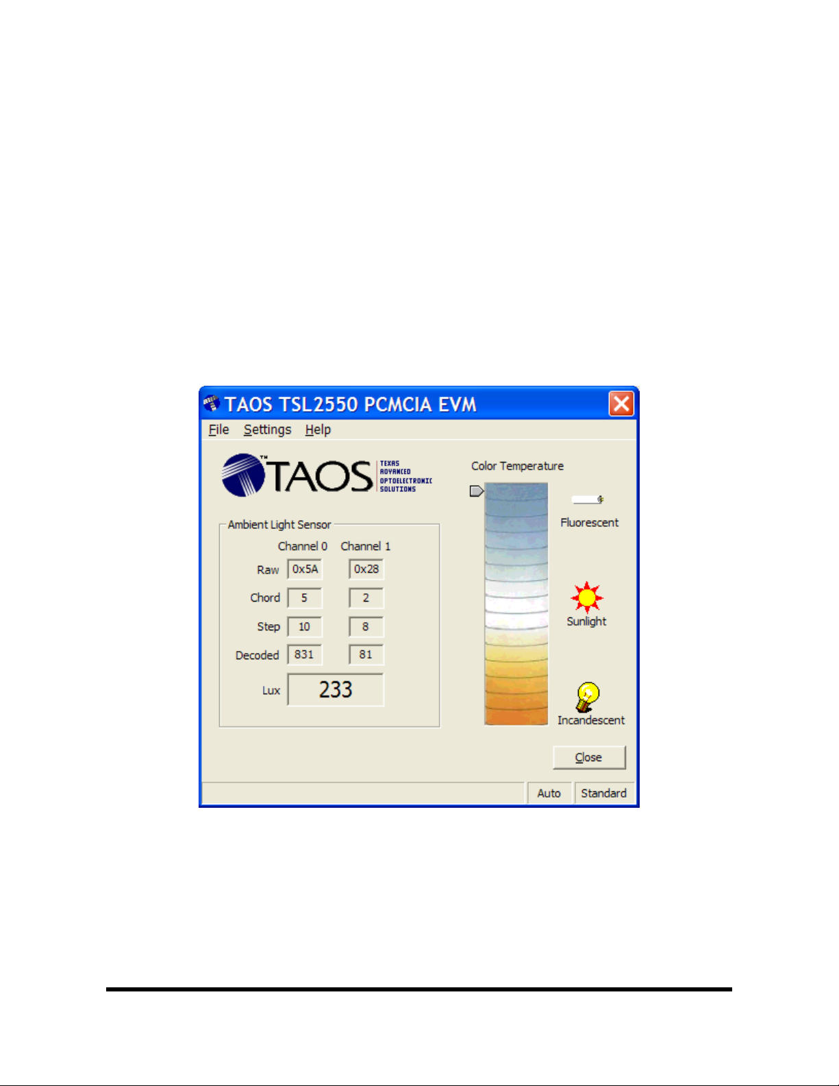
GETTING STARTED
On most PCs, installation will automatically start when the CD-ROM is inserted into the drive. If the
installation does not begin:
Click Start
Click Run
Type D:\setup and press Enter. IMPORTANT: Use the appropriate drive letter in the above
command to install the software. CD-ROMs are commonly D:
The installation program will guide you through the product installation
Refer to the ReadMe file on CD for the latest installation instructions.
Note: After inserting the PCMCIA card into the appropriate card slot, a message will be displayed on
the screen indicating that a new card was found and a driver needs to be installed. Follow the
instructions to install the driver and software. Below are some additional guidelines when using the
TSL2550 PCMCIA EVM:
Close the EVM application program before removing the PCMCIA card
Close the EVM application program when the computer is not in use so that the program is not
active when your computer goes into sleep mode
If more than one PCMCIA EVM card is used:
• Close the EVM Software
• Remove PCMCIA EVM card
• Insert new PCMCIA EVM card
• Activate EVM Software
Note: The TSL2550 Serial EVM software will automatically search for an available RS232
communication port until the serial EVM hardware is located.
www.taosinc.com
3 of 8