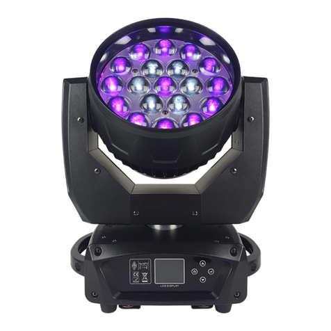
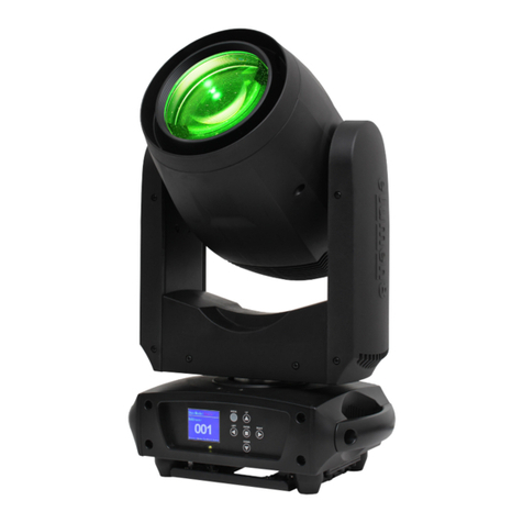
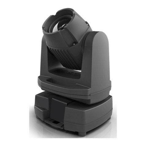
TAS ProSpot User manual

TAS s.r.l. Via Svizzera, 7
46042 Castel Goffredo (Mantova) Italy
tel. 0376 780497 - fax 0376 780844
1^edizione settembre 1999
1st edition september 1999
ProSpot

ProSpot
numero di serie/serial number
data di acquisto/date of purchase
fornitore/retailer
indirizzo/address
cap/città/suburb
provincia/capital city
stato/state
tel./fax/
Prendete nota, nello spazio apposito, dei dati relativi al modello e al rivenditore del vostro
ProSpot: in caso di richiesta di informazioni, pezzi di ricambio, servizi di riparazione o altro ci
permetteranno di assistervi con la massima rapidità e precisione.
Please note in the space provided above the relative service information of the model and the retai-
ler from whom you purchased your ProSpot: This information will assist us in providing spare parts,
repairs or in answering any technical enquiries with the utmost speed and accuracy.
ATTENZIONE: la sicurezza dell’apparecchio è garantita solo con l’uso appropriato delle presenti
istruzioni, pertanto è necessario conservarle.
WARNING: the security of the fixture is granted only if these instructions are strictly followed; the-
refore it is absolutely necessary to keep this manual.

Index
1.Packaging
2.Transportation
3.Important safety information
4.Lamp: installation and replacement
5.Operating voltage and frequency
5.1 Selecting operating voltage on the ProSpot power supply
6. Mounting the unit
7. Mains connection
8. Signal connection
9.Powering up
10.DMX addressing
11.Display panel functions
12.DMX 512 channel functions
13.Aligning the lamp in the optical path
14.Automatic repositioning features
15.Gobo Replacement
16.Maintenance
17. Test
17.1 Manual testing of each motor (MAnU)
17.2 DMX level readout (dMin)
17.3 Internal temperature readout (tEMP)
18.Function settings
18.1 Turning off the display (dISP)
18.2 Adjusting display intensity (dint)
18.3Inhibiting lamp on/off via DMX (dLoF)
18.4Adjusting fan speed (FAnS)
18.5 Automatic lamp on when fixture is switched on (LAAU)
18.6Resetting default function settings (dFSE)
19.Electronic alignment of motors
19.1Calibrating via an external signal source
19.2Calibrating via ProSpot’s on-board controls
20.Error messages
21.Spare parts
www.carlosmendoza.com.mx

Congratulations on having purchased a tas product. You have assured yourself of a fixture of the highest quality, both in
componentry and in the technology used. We renew our invitation to you to complete the service information on the previous
page, to expedite any request for service information or spares (in case of problems encountered either during, or subse-
quent to, installation). This information will assist in providing prompt and accurate advice from your tas service centre.
1. Packaging Following the instructions and procedures outlined in this manual will ensure the
maximum efficiency of this product for years to come.
Open the packaging and ensure that no part of the equipment has suffered dama-
ge in transit. In case of damage to the equipment, contact your carrier immediately
by telephone or fax, following this with formal notification in writing.
packing list
Ensure the packaging contains:
1 ProSpot
1 additional mounting plate
1 instruction manual
2. Transportation The ProSpot should be transported in its original packaging or in a tas approved
flight case.
We recommend the use of a suitable flight case which will stop the articulated
movement of the ProSpot during transportation.
www.carlosmendoza.com.mx

3. Important safety Fire prevention:
information 1. ProSpot utilises a Philips MSD 200w or 250w MH or equivalent lamp; use of
any other lamp is not recommended and will null and void the fixture’s warranty
2. Never locate the fixture on any flammable surface.
3. Minimum distance from flammable materials: 0,5 m.
4. Minimum distance from the closest illuminable surface: 2 m.
5. Replace any blown or damaged fuses only with those of identical values. Refer
to the schematic diagram if there is any doubt.
6. Connect the projector to main power via a thermal magnetic circuit breaker.
Prevention of electric shock:
1. High voltage is present in the internals of the unit. Isolate the projector from
mains supply prior to performing any function which involves touching the inter-
nals of the unit, including lamp replacement.
2. For mains connection, adhere strictly to the guidelines outlined in section 7 of
this manual.
3. The level of technology inherent in the ProSpot requires the use of specialised
personnel for all service applications; refer all work to your authorised tas servi-
ce centre.
4. A good earth connection is essential for proper functioning of the projector.
Never operate the unit without proper earth connection.
5. The fixture should never be located in an exposed position, or in areas of extre-
me humidity. A steady supply of circulating air is essential.
Protection against ultraviolet radiation:
1. Never turn on the lamp if any of the lenses, filters, or the housing is damaged; their
respective functions will only operate efficiently if they are in perfect working
order.
Never look directly into the lamp when it is operating.
Safety:
1. The projector should always be installed with bolts, clamps, and other fixings
which are suitably rated to support the weight of the unit.
2. Always use a secondary safety chain of a suitable rating to sustain the weight of
the unit in case of the failure of the primary fixing point.
3. The external surface of the unit, at various points, may exceed 80°C. Never hand-
le the unit until at least 10 minutes have elapsed since the lamp was turned off.
4. Always replace the lamp if any physical damage is evident.
5. Never install the fixture in an enclosed area lacking sufficient air flow; the
ambient temperature should not exceed 45°C.
6. A hot lamp may explode. always wait for at least 10 minutes to elapse after the
unit has been turned off prior to attempting to replace the lamp.
Always wear suitable hand protection when handling the lamp.
www.carlosmendoza.com.mx

4. Lamp: ProSpot utilises a Philips MSD 200W or 250W MH or equivalent.
Installation and The lamp is available from your authorised tas sales agent:
replacement tas cod. LM 5210
wattage 200 w
luminous flux 13500 lm
colour temperature 6600° K
base GY 9,5
approximate life 3000 hours
tas cod. LM 5214
wattage 250 w
luminous flux 17000 lm
colour temperature 6600° K
base GY 9,5
approximate life 2000 hours
The fixture’s internal temperature can reach 150° C after 5 minutes, with a maxi-
mum peak of 350° C; ensure that the lamp is cold prior to attempting removal. The
fixture should be allowed to stand and cool for 10 minutes prior to its removal.
MSD lamps are part of the mercury vapour family of discharge lamps and must be
handled with great care. The lamp operates at high pressure, and the slight risk of
explosion of the lamp exists if operated over its recommended life.
We recommend, therefore, that the lamp be replaced within the manufacturer’s spe-
cified lamp life.
mounting the lamp
1) Using a Philips head screwdriver remove the 4 which affix the top cover, located
as shown in the following diagram.
2) Remove the lampcover by removing the three thumbscrews as shown in the diagram.
Lamp cover
3 fastening screws
2 screws 2 screws
top cover
bottom cover
Attention
Disconnect mains prior to opening up the unit
www.carlosmendoza.com.mx

3) Locate the lampholder
4) Insert the lamp. The lamp is manufactured from quartz glass and should be hand-
led with care; always adhere to the instructions supplied in the lamp’s packaging.
Never touch the glass directly, use the tissue provided in the lamp’s packaging.
The GY 9.5 lampholder is asymmetrical in construction, therefore make sure that
the correct pin is lined up into its respective socket. DO NOT USE UNDUE
FORCE. In case of difficulty, re-read the instructions and repeat the procedure.
5) The optimal distance between the lamp and the lense is 1-1,5 mm. Should this
not be the case, use the adjusters located on the fixture to rectify this situation.
See chapter 14 “Aligning the lamp in the optical path”.
6) Reposition the lampcover and refasten the three thumbscrews. Next replace the
fixture’s housing and refasten the four screws.
Prior to igniting the new lamp, reset the lamp life counter as described in section
11 “Display panel functions.”
Attention: we recommend that the lamp be realigned in the optical train of the
unit to avoid overheating of the dichroic filters and other internal components of
the unit. refer to section 14 for instructions about this procedure.
www.carlosmendoza.com.mx

5. Operating voltage The projector may operate at either 208, 230 or 240 V.at 50 or 60 Hz; tas presets
and frequency (barring specific requests), a voltage of 230 V and a frequency of 50 Hz.
If this preset does not correspond with the conditions in your particular country of
operation, follow the instructions in the sections which follow.
Incorrect frequency and voltage selection will detrimentally affect the
operation of the projector.
5.1 Setting the operating frequency on the ballast of the ProSpot.
1) Remove the four screws (A) on the side plate of the projector’s base, using a
Philips head screwdriver; remove the plate, thereby allowing complete internal
access to the base of the ProSpot.
4) Locate the terminal block labeled 50 or 60Hz to which the cable determining ope-
rating frequency is attached.
5) Move this cable to either the 50 or 60Hz position as required.
6) After having moved the cable and tightened it firmly in place, replace the hou-
sing and refasten the screws (A).
www.carlosmendoza.com.mx

6. Mounting the unit mounting
ProSpot can operate in any mounting position.
The structure from which the unit is hung should be of sufficient rating to hold the
weight of the unit, as should any clamps used to hang the unit.
The structure should also be sufficiently rigid so as not to move or shake whilst the
ProSpot moves during its operation.
The M8 mounting holes in the base of the ProSpot marked A1 A2 B1 B2 allow
the projector to have hook clamps fitted for the purpose of hanging.
The mounting plate shown below may be affixed to the base of the ProSpot using
M10 bolts, the slots allowing varying angles of mounting to be attained as well
as being able to be mounted on truss of various dimensions.
protection against liquids
The projector contains electric and electronic components that must not come into
contact with water, oil, or any other liquid.
movement
The projector has a movement of 530° in the base and 280° in the yoke; DO NOT
place any obstructions in the path of the projector’s movement.
safety chain
The use of two safety chains (cod. 069) - fixed to the ProSpot and to the primary
suspension point, is highly recommended to protect against accidental failure,
however unlikely, of the primary suspension point.
If using an after-market safety chains not manufactured by tas, ensure that they are
of sufficient rating to hold the weight of the fixture.
The safety chains are affixed via the 2 holes provided in the base of the unit, as
shown in the following diagram.
risk of fire
Each fixture produces heat and must be installed in a well-ventilated position. The
minimum recommended distance from flammable material is: 0.5m. Minimum
distance from the object being illuminated is: 2 m.
www.carlosmendoza.com.mx

forced ventilation
You will note that the projector’s housing contains several air entry points and fan
outlets, positioned both on the head and the base of the unit; under no circumstan-
ces should any of these points be obstructed!
Obstruction of any of these points will result in the overheating of the unit, detrimen-
tally and seriously affecting the proper operation of the ProSpot.
On this point, read section 17.3 Internal temperature monitor (tEMP).
www.carlosmendoza.com.mx

7.Mains connection cabling
The mains cable provided is thermally resistant, complying to the most recent international
standards
NB: In case of cable replacement, similar cable with comparable thermal resistant
qualities must be used exclusively (cable 3x1.5 ø external 8 mm, rated 300/500V,
tested to 2KV, operating temperature -40° +180°).
mains connection
ProSpot can operate at voltages from 208V-230V-240V at 50 or 60Hz (operating
voltage and frequency can be selected as described in section 5 of this manual).
Prior to connecting the unit to your mains supply, ensure that the model in your pos-
session correctly matches the mains supply available to you.
For connection purposes, ensure your plug is of a suitable rating: 3 amps.
Locate the mains cable which exits the base of the unit and connect as shown
below:
protection
The use of a thermal magnetic circuit breaker is recommended for each ProSpot.
A good earth connection is essential for the correct operation of the fixture. Strict
adherence to regulatory norms is strongly recommended.
marrone - brown
blu - blue
giallo/verde - yellow/green
marrone - brown
blu - blue
giallo/verde - yellow/green
massa
ground
neutro
neutral
fase
phase
alimentazione
main
marrone - brown
blu - blue
giallo/verde - yellow/green
www.carlosmendoza.com.mx

8. Signal connection Control signal is digital, and is transmitted via two pair screened ø0.5mm cable.
Signal type is DMX 512, conforming to international standards; in order to reduce
production costs and to allow easy worldwide availability of parts, tas utilises only
XLR 3 plugs and sockets for signal connection. Pin connection conforms to interna-
tional standards:
pin 1= screening 0 V
pin 2= data -
pin 3= data +
Controller
DMX 512
OUT
3
2
1
3 pin XLR 3/F
3 pin XLR 3/M
out
Ad altri ProSpot
Connect to other ProSpot
in out
in
www.carlosmendoza.com.mx

Should your DMX 512 controller utilise only XLR 5 sockets, the polarity of pins 1, 2
and 3 must be preserved as shown. Do not connect pins 4 e 5.
pin 1= screening 0 volt pin 4= not connected
pin 2= data - pin 5= not connected
pin 3= data +
Ensure that all data conductors are isolated from one another and the metal hou-
sing of the connector.
Note: the housing of the cannon XLR 3 must be isolated.
Controller
Standard
DMX 512
OUT
3
2
1
5 pin XLR 5/M
3 pin XLR 3/F
out
Ad altri ProSpot
Connect to other ProSpot
in out
in
www.carlosmendoza.com.mx

9. Powering up After having followed the preceding steps, turn on the DMX 512 controller which
will be used to control the ProSpot. Following this, turn on the power to the projec-
tor, and turn on the projector’s power switch.The projector will perform a
reset function on all the internal and external motors. This will last
some few seconds, after which it will be subject to the external
signal from the controller.
DMX reception
The display will be static on to indicate that DMX 512 signal is being correctly
received.
If the display flashes, the projector is not receiving signal. Check your cabling and
the controller for correct functioning.
menu enter +--
www.carlosmendoza.com.mx

10. DMX addressing Each ProSpot utilises 14 (8 bit) or 16 (16 bit) channels of DMX 512 signal
for complete control.
To ensure that each projector accesses the correct signal, it is necessary to correctly
address each fixture. Any number between 1 and 512 can be generated via the
multifunction panel of the ProSpot.
This procedure must be carried out on every ProSpot being used.
When powered up initially, each projector will show A001 which indicates DMX
address 1
Using 8 bit resolution, a projector addresses as A001 will respond to com-
mands on channels 1to 14 from the DMX 512 controller. A second projector
should be addressed as 15, the third as 29 and so on until the final ProSpot is
addressed.
Using 16 bit resolution, a projector addresses as A001 will respond to com-
mands on channels 1to 16 from the DMX 512 controller. A second projector
should be addressed as 17, the third as 33 and so on until the final ProSpot is
addressed.
altering the dmx address
1) Press the enter button. The letter A in the display will flash.
2) Press the +or -buttons until the desired DMX address is displayed. The letter A in
the display will flash to indicate the selected address is not stored in memory.
3) Press the enter button to confirm your selection; the display will stop flashing and
the projector will now respond to the new DMX address.
4) To better understand the function of each channel, we refer you to section 12
“Control channel functions from a DMX 512 controller”.
5) To alter the functioning from 8 to 16 bit refer to section 11 “Display panel
functions”.
Important Note: Keeping the +or -button pressed will cause the display to alter
at increased speed, allowing a faster selection to be effected.
By pressing the -button, you may inadvertently select a DMX address which is not
being communicated to the fixture by the controller, for example 405. If this is the
case, the display will flash. You may solve this problem by altering the incorrect
DMX setting.
menu enter +--
www.carlosmendoza.com.mx

11. Display panel The display panel on the base of the ProSpot is used to display and set function
functions information and various parameters.
Altering the tas factory settings may vary the functioning of the projector, causing it
to not respond to external DMX 512 signal. Please read and familiarise yourself
with the following information very carefully before altering any selections.
rpan
This function inverts the movement for horizontal (pan) movements.
1) Press the +or –buttons until rpan (for pan direction) is displayed.
2) Press the enter button to confirm your selection; the display will show off (for
clockwise –standard operating mode).
3) Press the +or –buttons; the display will show on (for counter-clockwise).
4) Press the enter button to confirm your choice of pan movement.
rtilt
This function inverts the movement for vertical (tilt) movements.
1) Press the +or –buttons until rtilt (for tilt direction) is displayed.
2) Press the enter button to confirm your selection; the display will show off (for
clockwise - standard operating mode).
3) Press the +or –buttons; the display will show on (for counter-clockwise).
4) Press the enter button to confirm your choice of tilt movement.
menu enter +--
menu enter +--
menu enter +--
menu enter +--
menu enter +--
menu enter +--
www.carlosmendoza.com.mx

16br
This function varies the movement resolution from 16 bit to 8 bit. The number of
channels utilised by the projector thus become either 14 (8 bit resolution) or 16 (16
bit resolution).
1) Press the +or –buttons until 16br (for resolution) is displayed.
2) Press the enter button
3) Press the +or –buttons until on is displayed (16 bit resolution).
4) Press the enter button to confirm your selection.
5) Press the +or –buttons until off is displayed (8 bit resolution).
6) Press the enter button to confirm your selection.
LAti
This function provides information on the number of hours of operation of the lamp
in the unit.
1) Press the +or –buttons until LAti (for lamp life).
2) Press the enter button to confirm your selection; the display will show a numeri-
cal value which is the length of time in hours that the lamp has been operated
since the counter was last reset.
The lamp life counter needs to be reset to zero at every lamp change to provide
accurate information on lamp life
3) To perform a reset for this function, simultaneously press the +and -buttons and
the display will automatically reset.
4) Press enter to confirm the lamp life counter reset operation (LAti).
POti
This function displays the total number of hours which the ProSpot has been opera-
ted
1) Press the +or –buttons to display POti (for hours).
2) Press the enter button to confirm your selection; the display will show a numeri-
cal value which corresponds to the number of hours which the fixture has been
connected to mains power. Unlike LAti this function is not resettable.
menu enter +--
menu enter +--
menu enter +--
menu enter +--
menu enter +--
www.carlosmendoza.com.mx

LAMP
This function allows for the on/off control of the lamp via DMX512 signal, or for
the permanent on (disenabling DMX control of this function) of the lamp.
1) Press the +or –buttons to display LAMP (for lamp).
2) Press the enter button to confirm your selection; the display will show off (for
lamp off).
3) Press the +or –buttons to display on (for lamp on).
4) Press the enter button to confirm your selection. The lamp will come on if you
selected on and will remain off if you selected off.
dEMo
This function allows two types of self-test procedures to be carried out without the
need for an external controller.
Mod 1 is used to test single functions at the choice of the operator of the unit.
Mod 2 is used to run an automated test sequence of all the functions of the
ProSpot.
1) Press the +or –buttons to display dEMo (for demonstration).
2) Press the enter button
Mod1
1 Press the +or –buttons to display Mod1 if you wish to test single functions.
2) Press the enter button
3) Press the +or –buttons to display Pan (dEmo Pan movement).
4) Press the enter button.
5) The number of the display corresponds to the position of the projector. Press the
+or –buttons and the number will change in the range from 0 to 255 displaying
the complete movement of the projector in the pan direction.
6) Press the +or –buttons to display tilt (dEMo tilt movement).
menu enter +--
menu enter +--
menu enter +--
menu enter +--
menu enter +--
menu enter +--
menu enter +--
www.carlosmendoza.com.mx

7) Press the enter button
8) The number of the display corresponds to the position of the projector. Press the
+or –buttons and the number will change in the range from 0 to 255 displaying
the complete movement of the projector in the tilt direction.
9) Press the +or –buttons to display Foc (dEMo focus function).
10) Press the enter button
12)The number of the display corresponds to the position of the focus lens. Press the
+or –buttons and the number will change in the range from 0 to 255 displaying
the complete movement of the focus lens.
13) Press the +or –buttons to display Go (dEMo gobos).
14) Press the enter button.
15) All the gobos or effects in the gobo wheel will be displayed in turn. Whilst this
is being undertaken, the display will show run.
4) To return to normal operation, press the menu button repeatedly.
Mod2
1) Press the +or –buttons to display Mod2 (this function tests all the features of
the ProSpot and allows all the features of the unit to be viewed).
2) Press the enter button.
3) The display will show run and all the features of the fixture will be run.
rESE
This function causes a reset to occur in the case (however unlikely) that one or more
of the motors should lose its reference point.
1) Press the +or –buttons to display rESE (for reset).
2) Press the enter button to confirm your selection; all the motors will perform a
reset.
menu enter +--
menu enter +--
menu enter +--
menu enter +--
www.carlosmendoza.com.mx

12. DMX 512 channel If all procedures have been correctly carried out to this point, your DMX 512
functions controller will have control over all the functions of the ProSpot, as shown in the table
which follows. The difference between 16 or 8 bit operation depends upon what selec-
tion you made in section 11 of this manual.
channel
16 bit channel
8bit function typeof control effect decimal
1 1 Base (pan) coarse proportional coarse control of the base movement 0-255
2 2 Yoke(tilt)coarse proportional coarse control of the Yoke movement 0-255
3 Base(pan) fine proportional fine control of the base movement 0-255
4 Yoke(tilt)fine proportional fine control of the Yoke movement 0-255
53
Speedpan/tilt
movement step Max speed (tracking mode) 0
proportional Max speed from max. to min. vector mode) 1-249
step Max.speed,black-outwhilePAN,TILT
moving or color changes (tracking mode) 250-255
64
lampon/off,reset,
fansspeedcontrol step open, max. speed of fan 0
proportional open,min.speedoffan(silentoperation)
from 0 to 127 decreasing speed of fan 127
step Lamp ON, reset, open position 128-139
step No function 140-229
step Lamp Off after 3 sec. 230-239
step No function 240-255
7 5 colours proportional Open/white 0
proportional Turquoise 10
proportional Red 21
proportional Cyan 32
proportional Green 42
proportional Magenta 53
proportional LightBlue 64
proportional Yellow 74
proportional Green 85
proportional Pink 96
proportional Blue 106
proportional Orange 117
proportional Forwardsrainbow effectfrom fastto slow 128-190
step Norotation 191-192
proportional Backwardsrainboweffect fromslow to fast 193-255
8 6 no function step No function 0-255
9 7 effect-wheel step Open position (hole) 0-95
step 3-facetrotatingprism 96-159
step Prism/Gobo macros 160-255
step Macro 1160-167
step Macro 2168-175
step Macro 3176-183
step Macro 4184-191
step Macro 5192-199
step Macro 6200-207
step Macro 7208-215
step Macro 8216-223
step Macro 9224-231
step Macro 10 232-239
step Macro 11 240-247
step Macro 12 248-255
www.carlosmendoza.com.mx
Table of contents

