Soundoff Signal UltraLITE EL3H12A20 Series User manual

WARNING: Warning devices are strictly
regulated and governed by Federal, State and
Municipal ordinances. These devices shall be
used ONLY on approved vehicles. It is the sole
responsibility of the user of these devices to
ensure compliance.
!
WARNING
This product contains high intensity LED devices.
To prevent eye damage, DO NOT stare into light
beam at close range.
MOUNTING INSTRUCTIONS
Before starting the installation make certain
you have the correct bracket for your
application. A universal Deck/Dash mount
bracket is supplied. For other mounting
brackets, see product literature or visit our
website.
Install the UltraLITE by following the
assembly instructions provided with the
brackets and check for security.
Important: DO NOT over tighten mounting
screws or nuts. This could cause
permanent damage to the light or bracket.
Use appropriate hardware for mounting.
PATTERN SELECTION
Because of the variety of configuring
options see separate sheets for detailed
instructions
Input Voltage: 10-16Vdc
Current: 6 Amps Maximum
Wire Color Connect to:
Blue Input 1 / Left Input
Green Input 2 / Right Input
Brown Input 3 / Warning Input
Red +12Vdc
Black Ground (-)
White Pattern Select
WIRE HOOK-UP TABLE
EL3H12A(xxx) 2.09
BLACK
RED
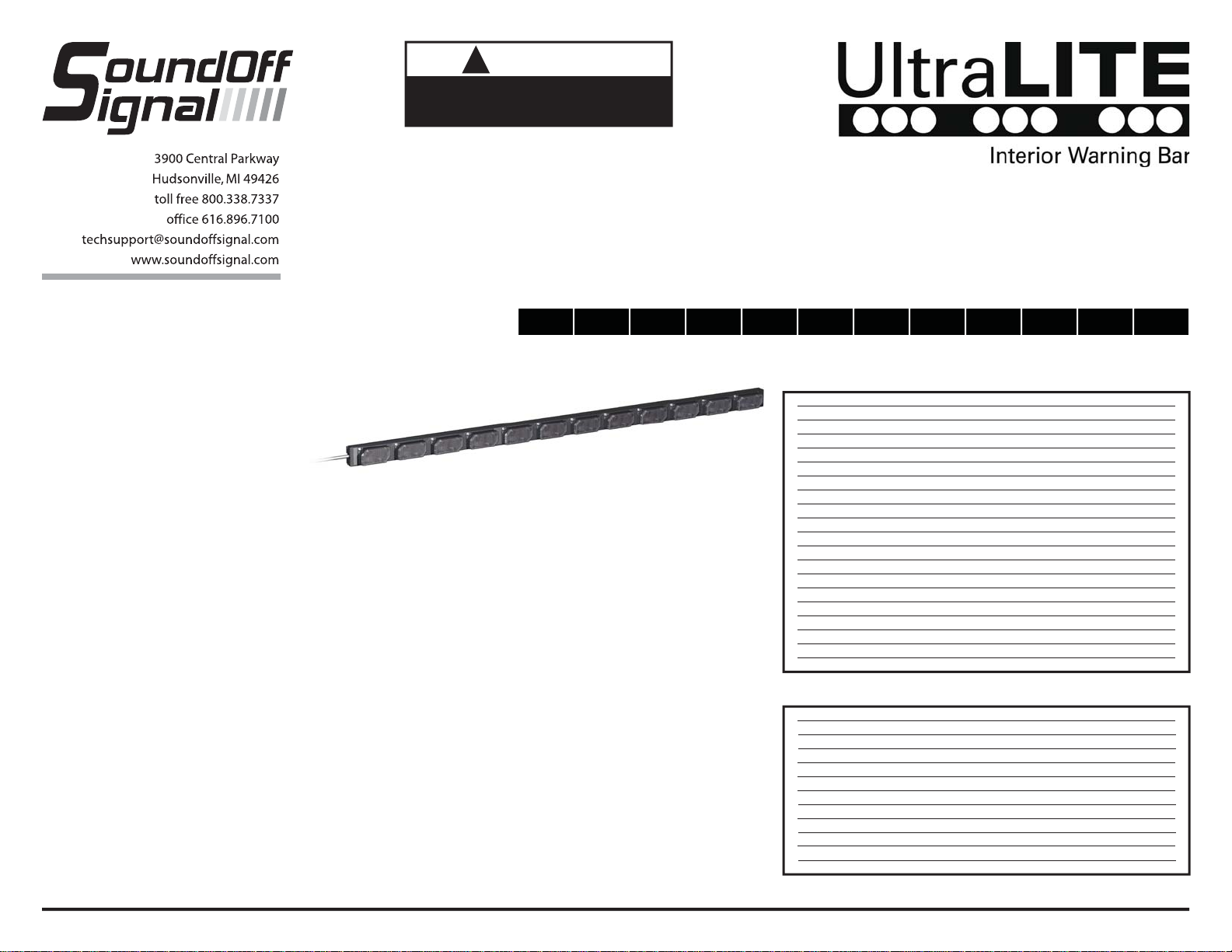
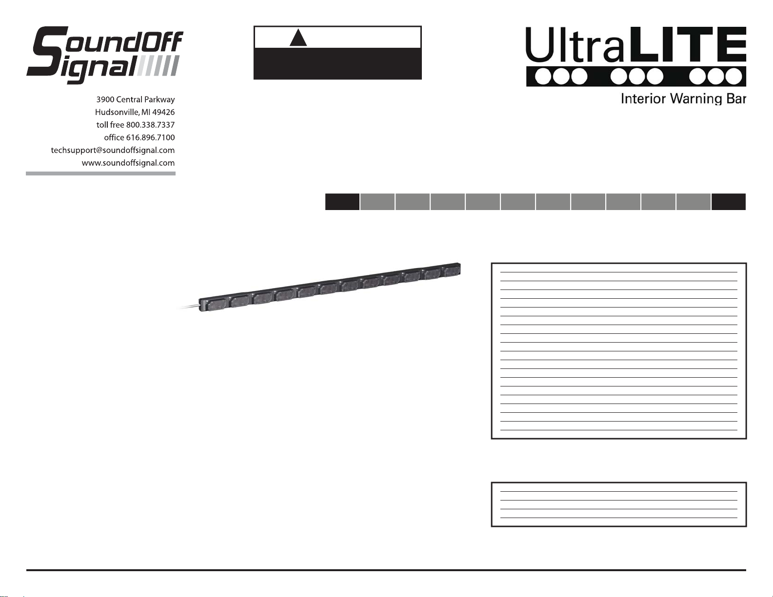
WHITE 12 MODULE UltraLITE
BROWN
GREEN
BLUE
+12Vdc
10A FUSE
12 MODULE BAR
ASSEMBLY INSTRUCTIONS
EL3H12AØØ(x)
UNIVERSAL BRACKET
SUPPLIED BAR
MOUNTING HARDWARE
WARNING: Warning devices are strictly
regulated and governed by Federal, State and
Municipal ordinances. These devices shall be
used ONLY on approved vehicles. It is the sole
responsibility of the user of these devices to
ensure compliance.
EL3H12A(xxx) 2.09
!
WARNING
This product contains high intensity LED devices.
To prevent eye damage, DO NOT stare into light
beam at close range.
PATTERN SELECTION
1. Connect BLACK wire to ground.
2. Connect RED wire to +12VDC.
3. Connect GREEN, BLUE and BROWN wires
to +12VDC.
4. With power applied to the three wires,
momentarily apply power to WHITE wire to
change the directional arrow patterns.
5. While changing patterns, the UltraLITE will
display the left arrow pattern.
6. When you have chosen the directional
pattern, disconnect GREEN and BLUE wires
from power.
7. With the BROWN wire connected to power,
momentarily apply power to WHITE wire to
change the arrow warning pattern.
8. When you have selected the arrow warning
pattern, disconnect BROWN wire from
power.
9. You are finished configuring the UltraLITE.
ARROW PATTERNS for
12 MODULE UltraLITE - EL3H12A00(x) 1 COLOR
1 Solid Fast High Power
2 Solid Plus Fast High Power
3 Sequential Fast High Power
4 Sequential2 (2 lights) Fast High Power
5 Chaser Fast High Power
6 Solid Slow High Power
7 Solid Plus Slow High Power
8 Sequential Slow High Power
9 Sequential2 (2 lights) Slow High Power
10 Chaser Slow High Power
11 Solid Fast Low Power
12 Solid Plus Fast Low Power
13 Sequential Fast Low Power
14 Sequential2 (2 lights) Fast Low Power
15 Chaser Fast Low Power
16 Solid Slow Low Power
17 Solid Plus Slow Low Power
18 Sequential Slow Low Power
19 Sequential2 (2 lights) Slow Low Power
20 Chaser Slow Low Power
12 MODULE BAR
FULL DIRECTIONAL ARROW
CONFIGURATION INSTRUCTIONS
EL3H12AØØ(x)
ARROW WARNING PATTERNS
1 Double Left and Right (Alternating)
2 Double Every Other Module
3 Q-Switch Left and Right (Alternating)
4 Q-Switch Every Other (Alternating)
5 Power Pulse Every Other (Alternating)
6 Power Pulse Left and Right (Alternating)
7 Quad Outer and Inner (Alternating)
8 Warp Every Other (Alternating)
9 Crossfire
10 HyperScan
11 SuperScan
12 Power Flash
Alternating: 1,2,3,4 alternates with 5,6,7,8
Every Other: 1,3,5,7 alternates with 2,4,6,8

WARNING: Warning devices are strictly
regulated and governed by Federal, State and
Municipal ordinances. These devices shall be
used ONLY on approved vehicles. It is the sole
responsibility of the user of these devices to
ensure compliance.
!
WARNING
This product contains high intensity LED devices.
To prevent eye damage, DO NOT stare into light
beam at close range.
PATTERN SELECTION
1. Connect BLACK wire to ground.
2. Connect RED wire to +12VDC power.
3. Connect BLUE wire to +12VDC power.
4. With power applied to BLUE wire, momentarily apply power
to WHITE wire to move forward one warning pattern.
5. When you have chosen your first warning pattern,
disconnect BLUE wire from power.
6. The pattern you have selected will always display on the
UltraLITE when power is applied to the BLUE wire.
7. To setup your next warning pattern, connect GREEN wire to
power.
8. With power applied to the GREEN wire, momentarily apply
power to WHITE wire to move forward one warning pattern.
9. When you have chosen you second warning pattern,
disconnect GREEN wire from power.
10. The pattern you have selected will always display on the
UltraLITE when power is applied to the GREEN wire.
11. To setup the last warning pattern, connect BROWN wire to
power.
12. With power applied to the BROWN wire, momentarily apply
power to WHITE wire to move forward one warning pattern.
13. When you have chosen your third warning pattern
disconnect BROWN wire from power.
14. The pattern you have selected will always be displayed on
the UltraLITE when power is applied to the BROWN wire.
15. You are finished configuring the UltraLITE.
EL3H12A(xxx) 2.09
FLASH PATTERNS
12 MODULE UltraLITE - EL3H12A00(x) SPLIT COLOR
1 Quint Flash Alternating
2 Warp Flash Alternating
3 Inter-cycle Flash Alternating
4 Double Flash Alternating
5 Quad Flash Alternating
6 3 Flashes / Second Alternating
7 3 Flashes / Second Simultaneous
8 Q-Switch Alternating
9 E-Pattern Single Flash Alternating
10 E-Pattern Double Flash Alternating
11 E-Pattern Single Flash Simultaneous
12 E-Pattern Double Flash Simultaneous
13 LiteRyder Sweep
14 Quint Flash Every Other Module
15 Warp Flash Every Other Module
16 Inter-cycle Flash Every Other Module
17 Double Flash Every Other Module
18 Quad Flash Every Other Module
19 Q-Switch Every Other Module
Alternating: 1,2,3,4,5,6 alternates with 7,8,9,10,11,12
Simultaneous: All modules on at same time
Every Other: 1,3,5,7,9,11 alternates with 2,4,6,8,10,12
12 MODULE BAR
6+6 SPLIT WARNING
CONFIGURATION INSTRUCTIONS
EL3H12AØØ(x)
WARNING: Warning devices are strictly
regulated and governed by Federal, State and
Municipal ordinances. These devices shall be
used ONLY on approved vehicles. It is the sole
responsibility of the user of these devices to
ensure compliance.
!
WARNING
This product contains high intensity LED devices.
To prevent eye damage, DO NOT stare into light
beam at close range.
PATTERN SELECTION
1. Connect BLACK wire to ground.
2. Connect RED wire to +12VDC.
3. Connect GREEN and BLUE wires to
+12VDC.
4. With power applied to the two wires
momentarily apply power to WHITE wire to
change the directional arrow patterns.
5. While changing patterns, the UltraLITE will
display the left arrow pattern.
6. When you have chosen the directional arrow
pattern, disconnect GREEN and BLUE wires
from power.
7. Connect BROWN wire to +12VDC and
momentarily apply +12VDC to WHITE wire
to change the warning pattern displayed on
the UltraLITE.
8. When you have selected the warning pattern
for the UltraLITE, disconnect BROWN wire
from power.
9. You are finished configuring the UltraLITE.
EL3H12A(xxx) 2.09
END MODULE WARNING
1 Traffic Mover Simultaneous
2 Q-Switch Alternating
3 RoadRunner Alternating
4 Power Pulse Alternating
5 Progressive Alternating
Simultaneous: 1 and 12 together
Alternating: 1 alternates with 12
ARROW PATTERNS for
12 MODULE UltraLITE - EL3H12A10(x) 10+2 COLOR
1 Solid Fast High Power
2 Solid Plus Fast High Power
3 Sequential Fast High Power
4 Sequential2 (2 lights) Fast High Power
5 Chaser Fast High Power
6 Solid Slow High Power
7 Solid Plus Slow High Power
8 Sequential Slow High Power
9 Sequential2 (2 lights) Slow High Power
10 Chaser Slow High Power
11 Solid Fast Low Power
12 Solid Plus Fast Low Power
13 Sequential Fast Low Power
14 Sequential2 (2 lights) Fast Low Power
15 Chaser Fast Low Power
16 Solid Slow Low Power
17 Solid Plus Slow Low Power
18 Sequential Slow Low Power
19 Sequential2 (2 lights) Slow Low Power
20 Chaser Slow Low Power
12 MODULE BAR
DIRECTIONAL ARROW
W/ SINGLE WARNING TIPS
CONFIGURATION INSTRUCTIONS
EL3H12A1Ø(x)

WARNING: Warning devices are strictly
regulated and governed by Federal, State and
Municipal ordinances. These devices shall be
used ONLY on approved vehicles. It is the sole
responsibility of the user of these devices to
ensure compliance.
!
WARNING
This product contains high intensity LED devices.
To prevent eye damage, DO NOT stare into light
beam at close range.
PATTERN SELECTION
1. Connect BLACK wire to ground.
2. Connect RED wire to +12VDC.
3. Connect GREEN and BLUE wires to
+12VDC.
4. With power applied to the two wires
momentarily apply power to WHITE wire to
change the directional arrow patterns.
5. While changing patterns, the UltraLITE will
display the left arrow pattern.
6. When you have chosen the directional arrow
pattern, disconnect GREEN and BLUE wires
from power.
7. Connect BROWN wire to +12VDC and
momentarily apply +12VDC to WHITE wire
to change the warning pattern displayed on
the UltraLITE.
8. When you have selected the warning pattern
for the UltraLITE, disconnect BROWN wire
from power.
9. You are finished configuring the UltraLITE.
EL3H12A(xxx) 2.09
ARROW PATTERNS for
12 MODULE UltraLITE - EL3H12A20(x) 8+4 COLOR
1 Solid Fast High Power
2 Solid Plus Fast High Power
3 Sequential Fast High Power
4 Sequential2 (2 lights) Fast High Power
5 Chaser Fast High Power
6 Solid Slow High Power
7 Solid Plus Slow High Power
8 Sequential Slow High Power
9 Sequential2 (2 lights) Slow High Power
10 Chaser Slow High Power
11 Solid Fast Low Power
12 Solid Plus Fast Low Power
13 Sequential Fast Low Power
14 Sequential2 (2 lights) Fast Low Power
15 Chaser Fast Low Power
16 Solid Slow Low Power
17 Solid Plus Slow Low Power
18 Sequential Slow Low Power
19 Sequential2 (2 lights) Slow Low Power
20 Chaser Slow Low Power
END MODULE WARNING
1 Traffic Mover Simultaneous
2 Q-Switch Alternating
3 RoadRunner Alternating
4 Power Pulse Alternating
5 Progressive Alternating
Simultaneous: 1-2 and 11-12 together
Alternating: 1-2 alternates with 11-12
12 MODULE BAR
DIRECTIONAL ARROW
W/ DUAL WARNING TIPS
CONFIGURATION INSTRUCTIONS
EL3H12A2Ø(x)
This manual suits for next models
2
Table of contents
Other Soundoff Signal Dj Equipment manuals

Popular Dj Equipment manuals by other brands


Chauvet Professional
Chauvet Professional OVATIONREVEE3IP Quick reference guide

Equinox Systems
Equinox Systems EQLED53 user manual

Chauvet Professional
Chauvet Professional onAir FLEX 12 Quick reference guide

Chauvet DJ
Chauvet DJ SWARM 4FX user manual

Fuzzix
Fuzzix MBW18LED instruction manual

ARRI
ARRI L Series user manual