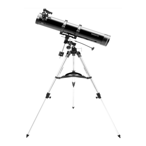
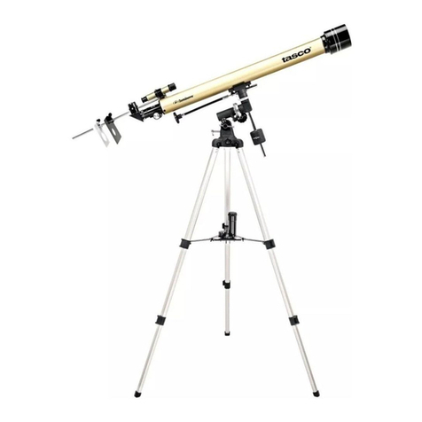
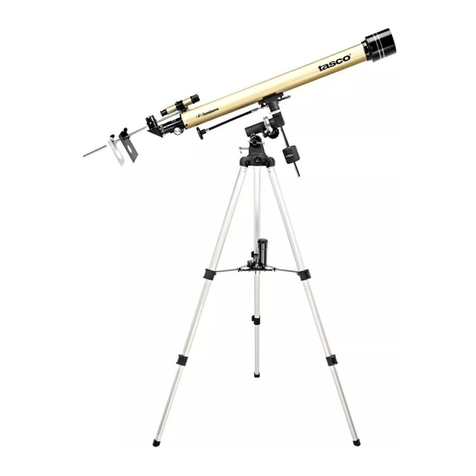
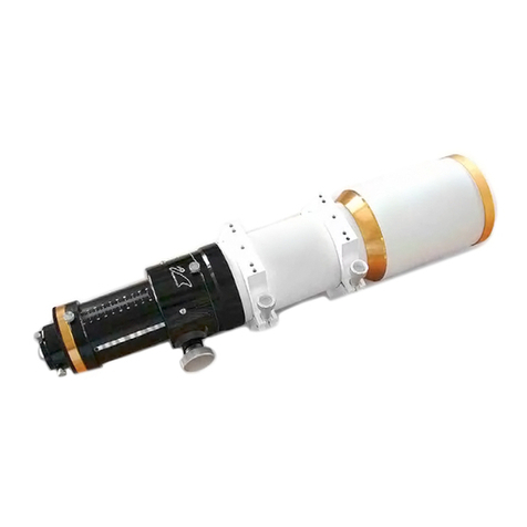
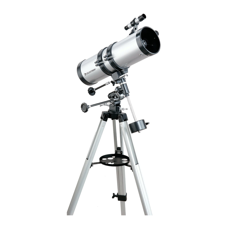
TAS 7 TE 304 User manual

..
.I
.
. I
..
. .
.'
~
TASC07T
'E !
;.
::,
304
POWER
TELESCOPE
TASCO
SALES
COMPANY
.
.
1075
N.
W. 71st
St
••
Miami.
Florida

~2
7
j
•••
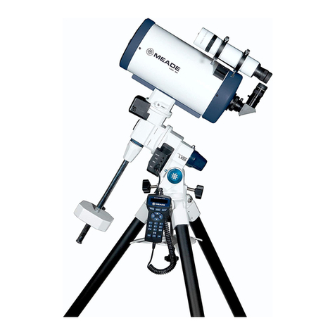
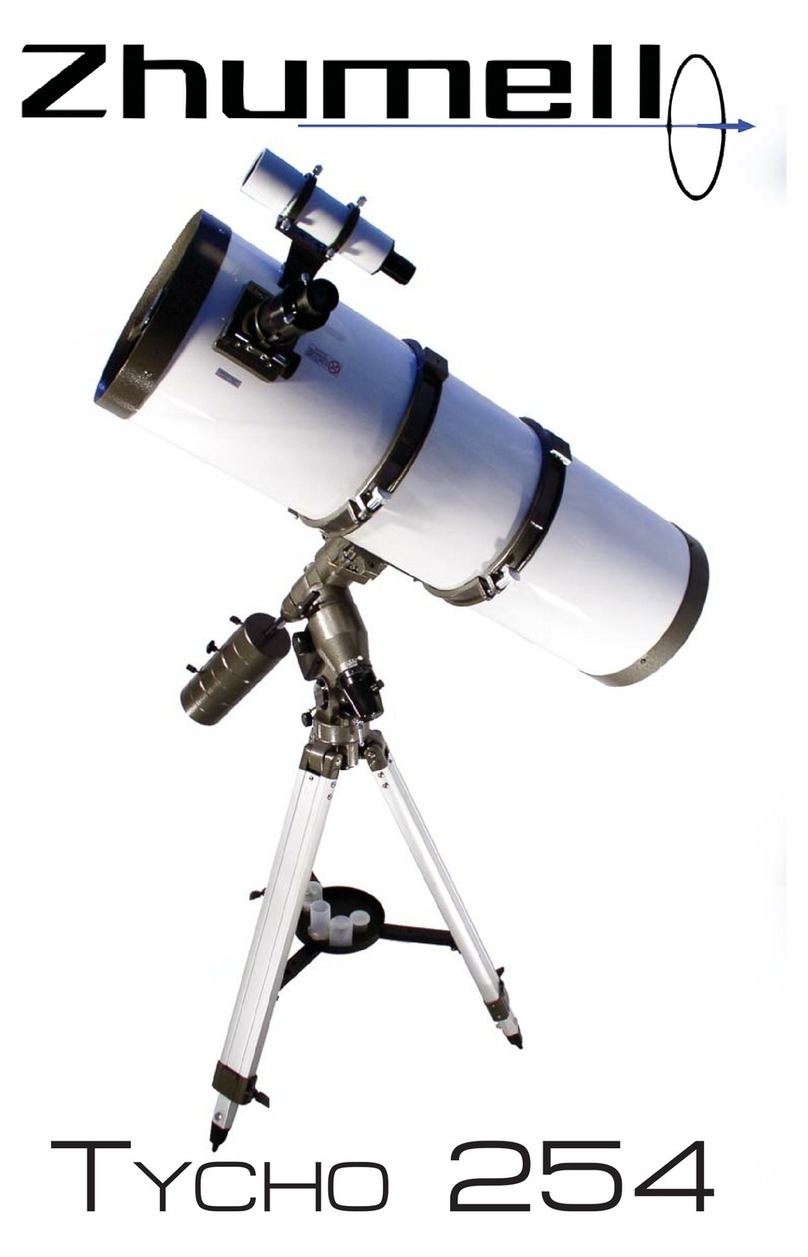
TELESCOPE PARTS
1.
Dust
Cap
2. Dew
Cap
3. Objective 'lens Mount with Squaring-On
Adjustment
4. Telescope Tube
5. Hinged Sleeve ..Type Telescope Tube
Holder ITrunnionl with Thumb Screw
S.
Declination Axis
7. Polar Axis Inclination Clamp
8. Azimuth Circle
9. Tripod Head Flange
10
. Balance
Weight
or Cour,terpoise
11. Focusing Mount and Finder Scope
12.
Micro
Focusing Knob with Pinion
.31
13.
Focusing Draw Tube with
Rack
14
. Eyepiece Sliding Sleeve
15, Polar Axis
16. Right Ascension Slow Motion Control
17. Declination Slow
Motion
Control
18
.
Sun
Projection Screen
19. Declination ' Axis Clamp Lever
20. Tripod
Leg
Bolt
21.
Base
of Tripod Head
22. Adjustable
Hardwood
Tripod
23. Tripod Stretcher and Accessories Tray
t 24. Tripod
leg
Set
Screws
25. Erecting
Prism
26. Barlow
lens
27. Star Diagonal Prism.
28. Eyepiece H20mm
29. Eyepiece HM12.5mm H9mm Eyepiece ....
..
.....
..
....
..
......
:.J.1~~_il.
30. Eyepiece HM6mm
SR4mm
Eyepiece
..
.......
..
.......... .227
31
.
Sun
Filter
Variable
8-20mm Eyepiece 45
to-.,..,-....-.~
32. Carrying Case
Sun
Di
agonal
Prism
,'
~
..
f ' , .
OPTICAL
EFFECT
Figure 1
ADDITIONAL
ACCESSORIES
AVAILABLE
AT
YOUR NEAREST
TASCO
HEADQUARTERS ,
AH40mm Eyepiece
..
.................... 23 Power
HM25mm Eyepiece ......
..
............ 36 Power
OBJECTIVE
(Fraunhofer type, Achromatic, Hard coated)
MAGNIFICATION
Astronomical
or
Terrestrial
2
Clear
Aperture
60mm
Focal
length
910mm
light
Gather-
ing Power
for
Naked
Eye
74X
Resolving
Power with
. Respect to
Double Stars
1.9"
Faintest
Discernible
Stars
lO.7m
Original
152X 73X
45X
With
Barlow
lens
304X, 146X
90X -

TASCO
7
TE
DESCRIPTION
GENERAL
Every
part
of
the
Model
7TE
telescope
is
con-
structed
of
the finest
quality
materials. It
is
designed
and
manufactured
to meet the exacting
requirements
of
critical astronomicaI observation.
All
lenses
are
hard
coated
with
magnesium
fluor-
ide
to
permit
maximum
light
transmission
and
are
fully
corrected
for
spherical
and
chromatic
ab-
beration
and
coma. The resolving
power
of
this
lens
combination
exceeds the Dawes limit emperi-
cal
criterion
necessary to secure a point image.
This
is
the most
improtant
factor
in stellar
observation.
MAGNIFICATION
The
normal
range
of
magnification
is
152X, 73X,
and 45X.
By
attaching
the
Barlow
lens
to
the
telescope eyepiece sliding sleeve, the
range
of
magnification
is
increased
to
304X, 146X,
and
90X.
In this
way,
the
Barlow
lens makes possible six
magnifications, using
only
three
eyepieces.
SQUARING.ON
ADJUSTMENT
The objective mount
is
equipped
with a special
device which permits
"squaring
on"
and
center-
ing the objective lens.
This
operation,
which con-
.
sists
of
setting the objective lens
at
a precise
right
angle
to the axis
or
centerline
of
the telescope
tube, removes distortion
of
the
type
described on
Page 6 under
"Squaring
On
of
the Telescope".
TELESCOPE
MOUNT
The design
of
the Tasca telescope mount
is
exceed-
ingly
practical
and
functional. The unique com-
bination
alt-azimuth
and
equatorial
mount makes
possible easier
and
more
varied
operation.
This
design
allows
the
use
of
the telescope
both
as
an
equatorial
telescope for astronomical observation
and
as
an
alt-azimuth
"elescope
for
terrestrial
observation. The
tripod
head may be revolved
on
the base
of
the
tripod
as
an
aid
to the azimuth
fine adjustment. There
is
also a
flexible
dntrol
at
the eye end
of
the telescope
for
slow motion
il' either
right
ascension
or
declination
in
any
observing position.
PULL·OUT
TUBE
There
is
a rack
and
pinion mechanism
and
on
adjustable
pull-out
tube
at
the eye end
of
the
telescope which provides quick adjustment when
installing new eyepieces.
EYEPIECES
The
Model
7TE
telescope
is
equipped
with
newly
designed eyepieces with
hard
coated lenses which
give
a sharp, wide,
and
flat
corrected field.
These
.
eyepieces, because
of
their special design,
are
simple to remove
and
easy to clean.
TRIPOD
The
solidly
constructed
tripod
has sliding legs
with steel fittings.
The
tripod
legs are held
firmly
iri place
by
the steel stretcher and accessories
tray.
There
is
sufficient adjustment in the
tripod
head to
make
it unnecessary to move the
tripod
while
observing. The
tripod
base
is
equipped
with
an azimuth circle,
gmduated
from 0 to 360
degrees, which makes possible easy
and
quick
equatorial
adjustment.
3

ASSEMBLY
Figure
2 DISASSEMBLY
Before
any
attempt
is
made
to
assemble
the
telescope,
fami.liarity
with
the
part
names
is
re-
In
general,
the
disassembly
procedure
is
lust a
commended.
Follow
the
assembly
and
disassembly
reversal
of
the
assembly
steps
listed
above.
First,
steps
carefully
to
avoid
damage
to
the
telescope.
remove
all
accessories;
then
unscrew
the
balance
weight.
Reverse
all
other
assembly
steps. Return
1. Remove
tripod
legs
from
the
carrying
case.
each
part
of
the.
telescope
to
its
original
location
collapsed
leg
ar)d
pullout
the
leg
extension
2.
Loosen
the
set
screw
at
the
lower
end
of
each
in
the
carrying
case.
about
half
way.
Tighten
the
set
screw
to
hold
Note:
Be
sure
the
small
white
bags
of
silica
gel
the
leg
in this
position.
are
not
removed
from
the
carrying
case. These
are
provided
to
absorb
moisture
which
might
from
the
carrying
case
and
set
it
aside
for
3. Remove
the
large,
white,
main
telescope
tube
otherwise
damage
the
delicate
mechanism
of
later
assembly.
the
telescope.
,[
4. Remove
the
three
long
tripod
leg
attaching
I
bolts
from
the
accessories
case
(F;gure
2).
.'
5.
Take
the
azimuth
head
out
of
the
carrying
case
and
stand
it
upright
on
the
tripod
leg
flanges
in
the
center
of
a
large
floor
area.
6.
Lay
each
tripod
leg
on
the
floor
so
that
the
slotted
e;ld
faces
a
tripod
leg
flange
of
the
azimuth
head.
Be
sure
the
hinged
moullt
for
attaching
the
accessories
tray
is
facing
down-
ward
on
each
leg.
7.
Spread
t.he
ends
of
each
leg
and
fit
them
onto
the
tripod
leg
flanges;
then
install
tre
long
bolt
and
wing
nut,
finger
tight.
8.
lift
the
azimuth
head
straight
up
until
it
is
supported
by
the
tripod
legs;
then
attach
the
accessories
tray
with
the
three
small
bolts
and
wing
ruts.
9.
Tighten
the
large
wing
nut
at
the
top
of
each
leg.
10.
Loosen
the
declination
angle
clamp
lever
and
tilt
the
upper
section
of
the
mount
(Figure
3);
then
retighten
the
clamp.
11.
Open
the
main
telescope
tube
mount
and
install
the
telescope
tube,
making
certain
that
the
vernier
focusing
knobs
are
pointed
down-
ward
(Figure
1).
Tighten
the
clamp.
12.
Screw
in
the
balance
weight
for
counterpoise.
13.
Attach
the
finder
telescope.
14.
Attach
the
flexible
drive
shafts
for
the
right
ascension
and
decl
ination
slow
motion
controls.
Figure
3
4

USE
OF
THE TELESCOPE
IN
EQUATORIAL
POSITION
BALANCE
Both the telescope tube and the counterpoise, or
balance weight, must be
carefully
balanced
during
every operation.
EQUATORI~L
ADJUSTMENTS
By
means
of
the built-in spirit level, determine
that the
top
of
the stand
is
level when set up
for
observing (Figure 4.)
To
save setup time, it
is
suggested
that
three stone
or
concrete blocks
with gunmetal or brass plugs inserted in them
be placed in a
triangle
so
as to accommodate
each
tripod
leg. The metal spikes
on
the
tripod
legs can be inserted into the plugs, thus assuring
corr-ect placement
of
the telescope each time.
Set
the telescope tube as nearly
parallel
to
the
polar
axis
as
possible. Next,
set
the
polar
axis
reasonably correct in azimuth
by
means
of
the
azimuth circle on the
tripod
base
and
a compass,
making
allowance
for compass
deviation
at
the
point
of observation. Adjust the
altitude
of
the
polar
axis to the
proper
angle
to
equal the
latitude
of
the place
of
observation.
As
a rule,
it
is
easier to
set
the
polar
axis
at
the correct
altitude
than it
is
to set it
at
the -meridian.
Direct the
polar
axis
toward
the true north pole
which lies
about
one degree (two
full
moon
breadths) distant from Polaris
and
on a line be-
tween Polaris and
Alkaid
(7]
Ursae Majoris), the
latter being the last star in the tail
of
the
Great
Bear or Big Dipper. For best results, choose a
time for observing Polaris
as
it transits above or
.-
below
the pole Center Potaris in the field
of
view
of
the telescope; then raise or lower the
polar
axis, not over one degree,
by
means
of
the
Inclination and azimuth adjustments. This should
establish the
polar
axis
accurately
enough to
enable
locating an obiect in the field
of
view
of
the finder telescope.
Assuming that the
altitude
of
the
polar
axis
is
apprOXimately correct, here
is
a simple rule
to
refi
ne
the setting:
Center a star in the field
of
view
of
a moderately
high powered eyepiece.
If.
the
polar
axis
is
not
In
the meridian, it
will
be necessary
to
move the
declination and hour
angle
settings
to
keep the
star centered If the correct:on in declination was
Figure 4
toward
the
North
in the northern hemisphere
or
toward
the South in the southern hemisphere, the
upper end
of
the
polar
axis
is
pointing too
far
westward. If the correction
is
in an opposite
direction
to
that described, the
polar
axis
is
point-
ing too
far
eastward. Shift the
polar
axis in
azimuth'
in the direction indicated
and
make a
fresh trial.
One
or
two
such
trials should put the
polar
axis in sufficiently close adiustment
for
most practical purposes.
Use
two
ar
three stars
in Widely separated parts
of
the sky
for
each trial
Because
of
its
rapid
motion in declination,
the
.moon does not make a practical check point.
When
the declination
and
the hour
angle
have
been
properly
adiusted, the obiect
will
be near
the
middle
of
the field
of
view The finder teles-
cope
is
an
aid at this point
by
showing on a small
scale the
configuration
of the stars involved.
In
the main telescope, it
is
preferable
to
use
a
low
power
eyepiece to locate the desired image.
In
the case
of
an asteroid,
faint
satellite,
or
other
object producing a star-like image, it may be
necessary
to
plot
a position on a star chart to
distinguish this image from a star
Once on
obiect
is
in the center
of
the field
of
view, it
will
stay there since the telescope
is
now
following
the stars in their diurnal motion.
USE
OF
THE TELESCOPE IN
TERRESTRIAL
POSITION
To
observe terrestrial objects, place the telescope
in the position shown (Figure 6).
To
produce
images having minimum distortion and which
are
right
side up,
use
the erecting prism and a
low
power eyepiece.
5

SQUARING
ON
OF
THE
TELESCOPE
Figure 7
J6 perform perfectly, the objective lens must be
set
at
a right
angle
to
the axis, or centerline,
of
the telescope tube.
This
is
called
"squaring
on"
the telescope.
Choose a time when the atmosphere
is
steady
and
free from
cross
currents. Select
on
eyepiece
of
152X or more. Sight on a fixed star
of
the second
magnitude. If the telescope
is
squared on, this
star should
appear
as
a minute,
well
defined,
circular disk
of
light,
surrounded
by
one or
two
thin, concentric,
bright
rings (Reference A Fig. 7).
If the telescope
is
not
properly
squared on, the
light
from the star enters the telescope
obliquely
and
the image
is
distorted. It
will
appear
as
on
irregular
image with a
toil,
or
como, on one side
(Reference B or C, Figure 7). This condition
is
most evident when the image
is
just out of focus.
A n c
Figure 8
To
correct this distortion, adjust the screws on the
objective mount to effect
proper
alignment
.
When
the disk
is
not circular
but
appears
as
a distorted
ellipse, the condition
is
known
as
flexor, or
astigmatism
of
the objective lens.
To
squareon
in the
daytime,
follow
this procedure,
1.
Remove the eyepiece from the sliQing sleeve.
2.
Cover the objective lens with the dust
cop
or
a
block
cloth.
3.
Look into the objective lens from the end
of
. the eyepiece sleeve. Ghost images
of
reflected
light
from every surface
of
the -lens
will
be
seen. If these ghost images
are
seen
as
co[1-
centric circles (Reference A, Figure 8), the
telescope lenses
are
properly
aligned.
If these
ghost images
appear
as
difussed circles
(Re-
ferences B
or
C,
FigureS),
the alignment
is
.
incorrect.
CARE
OF
THE
TELESCOPE
AND
ACCESSORIES
THE OBJECTIVE
LENS
A
good
objective lens
is
very
highly
polished. It
must be cleaned as
carefully
and
rarely
as pos-
sible
to
ovoid
affecting
its accuracy and per-
formance. The lenses must never be token out
of
their mount
by
on
inexperienced person. They
should be held in the mount with .just enough
looseness
to
allow
a slight
rattle
to
be heard when
the mount
is
shaken
gently.
If the
"squaring
on"
adjustment screws or the moun.1
collar
screw
are
over tightened, the
I~nses
may
be put under
'-
"'=r
,.
.".
d f
strain
to
mw
. perrec! e inition.
CLEANING
THE
LENSES
I"
When
it becomes necessary
tO,tlean
the lenses,
"
:/
"
~
first remove Jhe dust with a
cam~1
hair
brush
or
a
,
~
.' :syringe; then place a few
drops
of
either
or
',p
'"
.
:
~
'
~.
-'
alcohol on a piece
of
very fine,
cI
.ean, wash-
leather, or
worn
out cotton cloth and
wipe
the
lenses very
gently,
avoiding
a circular motion.
SUDDEN TEMPERATURE
CHANGES
If possible,
ovoid
taking
the
telescope from cold
outside
air
into a worm room. This
will
couse the
objective lens
to
become covered with condensed
moisture, a condition which must be corrected
at
once.
To
do
this, place the objective lens
at
a
safe distance from the heat source and
ret
it
worm slowly until the moisture disappears.
Any
stains left on the lenses must
be
carefully
wiped
off
after
the lenses
are
thoroughIy
dry
.
Set
up
the telescope outdoors
in
cold weather
at
least
on~
hqlf hour
before
use.

,
. -
USE
OF
THE
ACCESSORIES
EYEPIECE
Place
the
eyepiece
in
position
by
pushing
it
into
the
eyepiece
s
liding
sleeve.
To
focus,
turn
the
slow
motion
focusing
knobs.
Engraved
on the
cap
is a
letter
and
number
symbol.
The
letiers
H
or
HM
stand
for
Huygenian,
or
Huygenian
Mittenzwey,
while
the
numbers
represent
the
focal
length
of
the
eyepiece
expressed
in
millimeters.
The
magnifying
power
of
the
telescope
can
be
obtained
by
dividing
the
focal
length
(Fo)
of
the
objec
ti
ve
lens
by
the
focal
len
gth
(Fe)
of
the
eye-
piece.
Thus,
if
the
focal
length
o.f
the
objec
ti
ve
lens is
910mm
and
that
of
the
eyepiece
is
125mm,
the
magnifying
power
is
910
divided
by
125;
or
73X
.
Observers
who
wear
other
than
astigmatic
eye-
glasses
should,
if
possible,
remove
them
before
viewing
.
BARLOW
LENS
The
use
of
the
Barlow
lens
doubles
the
magnify·
ing
power
of
the
telescope.
To
install
this lens,
slide
it
into
the
eyepiece
sliding
sleeve
to
the
cen
ter
of
the
sleeve;
then
slide
the
eyepiece
into
the
Barlow
lens
tube.
STAR
DIAGONAL
PRISM
This
device
is an L
shaped
tube
containing
a
right
angle
reflecting
prism.
It
passes
all
the
light
and
makes a
comfortable
position
possible
when
viewing
stars
at
a
high
altitude.
In
se
rt
the
prism
in
place
of
the
eyepiece
and
slip
the
eyepiece
into
the
prism
sleeve
(Figure
11).
When
the
prism
Figure
11
is
used,
the
draw
tube
must
be
pushed
in
about
60mm
to
provide
a
proper
lig
·
ht
path.
With
the
prism
installed,
the
image
is
erect
but
the
right
and
left
sides
are
reversed.
SUN GLASS
The
sun
glass
intercepts
the
heat
and
glare
of
the
sun's
rays
and
permits
safe,
direct
solar
ob-
servation.
In
use,
it
is
screwed
into
the
end
of
the
eyepiece.
FINDER TELESCOPE
The
small,
6X,
finder
telescope
is
mounted
by
fixed
supports
on
the
large
telescope
tube
and
is
parallel
to
it.
Its
objective
lens has a
focal
length
of
30mm
in
clear
aperture
and
is
equipped
with
cross
wires
on
the
field
of
view.
Both
the
eyepiece
and
the
objective
lens can
be
focused
separately.
First,
bring
the
object
into
view
by
means
of
the
eyepiece
and
cente
r
it
on'
the
:
·
·bos~
wires;
then, using the
objective
lens,
bring
the
object
into
sharp
focus.
It
is
difficult
to
locate
an
object
when
high
powers
'
are
used
because
of
the
small
field
of
view.
The
function
of
the
finder
telesc
ope
is
to
find
an
object
through
the
use
of
. its
wide
field
of
view
which
allows
the
scanning
of
a much
greater
area
of
the
skey
from
any
position.
Once
the
desired
ob-
jec t is
located
in the
center
of
the cross
wires
of
the
finder
telescope,
it
should
automatically
be
in the cen
ter
of
the
field
of
view
of
the main
telesc
ope.
If
this
does
not
prove
to
be
so,.
per·
form
this
simple
check:
In
the
daytime,
use a
distant
weather
vane,
rod,
or
other
similar
object
and
at
night
use a
bright
star
upon
which
to
focus
and
center
the
finder
telescope.
Cross
check
the images in
both
instru-
ments
to
see
if
they
are
centered,
'using a
low
power
eyepiece
in the main
telesc
ope.
If
the
images
are
not
both
centered,
adjust
the
direc-
tion
of
the
finder
telescope
by
means
of
the
ad-
justing
screws
so
as
to
align
the
axes
of
both
the
finder
and
the
main
telescope.
Replace
the
low
power
eyepiece
with
the
desired
high
power
eyepiece
and
perfect
the
adjustment.
ERECTlNiG PRISM
Since
an
astronomical
telescope
shows
an
inverted
image,
an
erecting
prism is
needed
for
terrestrial
purposes. The
erect
image
is
obtained
by
using
two
right
angle
pr
rs
ms.
·
An
ordinary
astronomical
eyepiece
is
used
instead
of
an
erecting
eyepiece.
This markes
possible
a
wide
field
of
view
and
less
loss
of
light.
When
erecting
prism is
used,
the
draw
tube
must
be
shortened
approximately
100mm
.
SUN PROJECTING
SCREEN
The
image
of the
sun
is
projected
through
the
telescope
onto
a screen.
Assemble
the
sun
screen
as
shown
(Figure
12).
When
attaching
the
ring
figure
12
of
the
rod
holding
the
screen
to
the
draw
tube,
.
be
sure
that
the
grooved
side
of
the
ring
is
directed
toward
the
tube.
For
best
results,
use
a
paper
clip
to
fasten a
sheet
of
white
paper
to
the
reflecting
side
of
the screen. Use
the
H20mm
eyepiece
for
projection.
The
image
obtained
will
be
10cm
in
diameter.
To
ob
tain
an
upright
image
on
the
screen,
use
the
diagonal
prism.
To
get
a
magnified
view
of
of
sun
spots,
use a
higher
powered
eyepiece.
7

NOTES
ON
OBSERVATION
OllSERVING THE
SUN
Proper
~
precauti::>ns to prevent blindness must be
taken in
v
iewin
,
~
the sun, The
use
of
the
sun
projection
screen
is
. recommended. However, If
it
is
desired to
view
the sun
directly
through
the
telescope,
use
the
following
procedure:
1.
Use
the
sun
glass on the eyepiece.
2:
Make
a stop
of
cardboard
or
thin sheet metal
with a circular hole
of
2 inches
or
less
in
diameter. Fit this over the
objective
lens
to
reduce the
a~ount
of
transmitted light
and
heat. Do not make the hole too small, as this
will
tend
to
reduce the sharpness
of
definition,
OBSERVING THE
MOON
The moon' has been a
favorite
target
of
observers
since
Galileo
first viewed it in 1610, Because
of
the
moon
's
comparative
proximity
to
earth,
it
is
the easiest
and
most interesting
object
for
the
viewer,
Craters, mountain ranges, valleys,
and
other
lunar
landscapes
are
best viewed when
they
lie near
the
dividing
line between the sunlit
and
dark
por-
tions
of
the moon, The best time
for
lunar
viewing
is
between the new moon
ana
a
dey
or
two
before
it
is
f01
'1
and
a similar interval
after
the full moon
and
the next new moon. The
bright
streaks
radi-
'"
ating
. from such
prominent
craters
·as
Tycho,
Copernicus, Kepler,
and
others
are
very
con-
sp
icuous
unde~
a high
light
at
or
near the
time
of
the full moon,
To observe the moon
generally
, the 73X
magnifi-
cation
is
the most suitable. This
will
bring
into
view
the phenomenon
of
earth-shine~
the
vast
seas
of
solidified
lava, the
land
s
cape
of
the
lurtar mountains,
and
the
variety
of
the phases
of
the moon. Every increase in
optical
power
increases the
recognizable
,features.
Higher
magni-
fications
will
bring
out in
greater
detail
the
craters, valleys,
and
clefts. Reference should be
made
to
lunar maps
as
an
aid
in
locating
specific
area
s.
OBSERVING THE PLANETS
Mercury
and
Vellus
are
known
as
inferior
planets
because their orbits
are
nearer to the
sun
than
is
the earth's
orbit.
The superior planets are those
whose orbits
are
farther
away
from the
~un
than
is
the'
earth~sorbit.
Mercury
-This'
planet
is
never seen in the south-
ern
sky, It
may
be seen in
April
or
October
,
ot
the time
of
its greatest elorrgation east
or
west.
8,
It must be viewed either in the
twilight
sky
very
shortly
after
sunset
Of
just
before
sunrise. Since
Mercury
can never be more than 28°
to
one
side
or
the
other
of
the
sun
, it
is
only
visible very
near
the
horizon
for
a short time,
not
more than
two
hours. This
planet
is
viewed through
the
dense
and
turbid
layer
of
the
earth.
As a result,
Mercury
has a reddish
appearance
and
is
seen
to twinkle, It discloses phases similar to those
of
Venus
and
its
tiny
disc
is
seldom
well
placed
for
observation,
Venus -This
planet
is
never seen in the south-
ern sky. It
is
the
third
brightest
object
in the sky,
exceeded
only
by
the
sun
and
the moon, It '
is
as
bright'
as
magnitude
4.4
and
is
twelve
times
the
magnitude
of
Sirius, Thls
peak
brilliance
oc-
curs in those years when it
is
a't
'perihelio(l,
near
the end
of
December. Venus
is
best viewed
at
tWilight
or
just
before
dawn,
when the
faint
light
of
day
serves
to
reduce its
brilliance
, It"
is
so
near the
horizon
that
its
image
is
distorted
because
of
the unsteadiness
of
earth's
atmosphere
,
When
near
inferior
conjunction, Venus
is
often
bright
enough
to
be seen
with
the
naked
eye
in
broad
daylight.
Its
phase
is
a thin crescent.
Mars
-This
planet
most closely resembles
earth
.
.
Near
the
Opposition,
when
Mars
is
nearest
to
earth, some
swfoce
detail
and
white
polar
caps
may
be observed with the
use
of
at
least 152X
magnification,
The details
of
its
orange-reddish
disc
may
be viewed, but a red
filter
is
recom-
mended to make a distinct contract
between
the
green markings
and
the reddish
background,
Jupiter -This
planet
offers
many
points
of
interest
that
can
be seen very
clearly
. A
fine
parallel
belt
lies
around
the
planet's
equator,
The
Great
Red
Spot lies on its
golden-yellow
disc.
The
four
Galilean
satellites
are
clearly
discern-
ible
,
With
every
increase in
magnitude,
more
d~
r'
tail
is
brought
out
in these markings, The
fo~r
brightest satellite:;
of
Jupiter cause transit, shadow,
eclipse,
and
occultation,
all
of
which
are
readily
seen.
Saturn -This
planet
and
its rings
are
perhaps
the mosl unusual speciac.le in the sky. A thin,
flat
band
which surrounds' the
dull
yellow
globe
of
Saturn
is
divided
into
two
con<;entric rings
by
"Cassini's Divison", The
faint
parallel
belt
mark-
ings
and
five
of
the planet's tell known satellites
can be
plainly
seen~
Uranus
and
Neptune
-Both
of
these planets can
be seen
very
easily. Uranus presents a
vogue
greeflish shope,
Neptun
e presents a faint, irreg\J-
lar,
slightly
greeni
,
sh
disc. The use
of
the
American
Ephemeris
and
N'autical
Almanac
will
facilitate
the
location
of
these.
planets.
Printed
in
Japan
. j
Table of contents
Other TAS Telescope manuals
