Tate SmartAire MZ Basic Troubleshooting guide
User Installation Manual
r1.9-3/11/15 SmartAire®MZ
7510 Montevideo Road © 2014 Tate Access Floors, Inc.
Jessup, MD 20794
Tel (410)799-4200 1 of 26
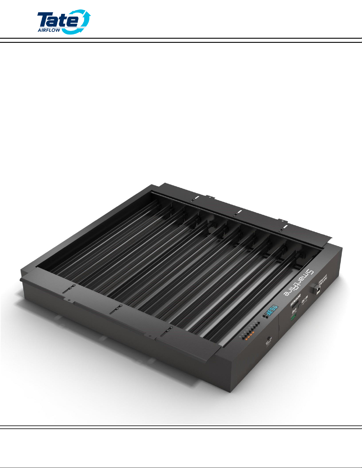
SmartAire®MZ
User Installation Guide
Please Read and Save
These Instructions

User Installation Manual
r1.9-3/11/15 SmartAire®MZ
7510 Montevideo Road © 2014 Tate Access Floors, Inc.
Jessup, MD 20794
Tel (410)799-4200 2 of 26
CONTENTS
Introduction ............................................................................................................................................................................ 3
Safety .................................................................................................................................................................................. 3
Included Components ......................................................................................................................................................... 5
Additional Required Components....................................................................................................................................... 5
Required Tools .................................................................................................................................................................... 5
Additional Notes ................................................................................................................................................................. 5
Quick Installation –Aluminum DirectAire® ............................................................................................................................ 6
Quick Installation –Steel DirectAire® ..................................................................................................................................... 6
Initial Setup ............................................................................................................................................................................. 7
Step 1: Prepare the Job Site ................................................................................................................................................ 7
Step 2: Route the temperature Sensors ............................................................................................................................. 8
Step 3: Attach the Sensors to the Rack Face....................................................................................................................... 8
Step 4: Connect the Sensors to the Tree ............................................................................................................................ 9
Step 5: Connect the Tree to the SmartAire® MZ................................................................................................................. 9
Step 6: Turn the Battery On .............................................................................................................................................. 10
Step 7: Connect the Power to the SmartAire® MZ ........................................................................................................... 11
Step 8: Deploy the Air Blockers......................................................................................................................................... 12
Step 9: Assemble the SmartAire® with the DirectAire® Al................................................................................................ 13
Step 9B: Installation with DirectAire®............................................................................................................................... 14
Step 10: Place the Assembly into the Floor ...................................................................................................................... 15
Interface................................................................................................................................................................................ 16
Changing Modes................................................................................................................................................................ 16
Regional Unit Conversion.................................................................................................................................................. 17
Disabling Unoccupied zones ............................................................................................................................................. 17
Adjusting the setpoint....................................................................................................................................................... 17
TCP/IP Advanced Programming & monitoring ..................................................................................................................... 18
SNMP Monitoring and Control.............................................................................................................................................. 23
Wiring Diagram ..................................................................................................................................................................... 24
Factory Default Settings........................................................................................................................................................ 25
Troubleshooting & Alarms .................................................................................................................................................... 26

User Installation Manual
r1.9-3/11/15 SmartAire®MZ
7510 Montevideo Road © 2014 Tate Access Floors, Inc.
Jessup, MD 20794
Tel (410)799-4200 3 of 26
INTRODUCTION
Thank you for choosing a Tate Airflow product. Tate Airflow products are engineered to maximize the
efficiency of your data center air handling system. We would be interested in hearing any comments you may
have on this installation manual, product, or overall experience. Please call or e-mail our Technical Service
Department:
Phone: 410-799-4200
SAFETY
Wear personal protective equipment (PPE) as applicable during installation. PPE may include gloves,
safety eyeglasses, hardhats, or additional equipment depending on exact job site conditions.
Do not leave the site unattended until the installation is complete.
All work conducted on units should only be conducted by a trained professional.
Modifying equipment other than in ways suggested and approved by Tate are not recommended or
supported and may damage equipment or cause harm.
It is recommended that the on board battery pack is tested yearly to ensure proper function and
failsafe operation. (As described in the Troubleshooting Section.)
It is recommended that the on board battery pack is replaced by a trained professional at least once
every five years to ensure proper function and failsafe operation.
Batteries should be disposed of by an approved technician.
Regulations vary for different countries, Dispose of in accordance with local regulations.
Environmental Conditions:
Ambient Operational & Storage conditions:
oTemperature (°c) : 5 to 45
oRelative humidity (%): 20 to 80
CAUTION
RISK OF EXPLOSION IF BATTERY IS REPLACED BY AN INCORRECT BATTERY TYPE.
DISPOSE OF USED BATTERIES ACCORDING TO THE INSTRUCTIONS AND LOCAL
ACCORDANCES
User Installation Manual
r1.9-3/11/15 SmartAire®MZ
7510 Montevideo Road © 2014 Tate Access Floors, Inc.
Jessup, MD 20794
Tel (410)799-4200 4 of 26
SÉCURITÉ
Portez de l’équipement de protection individuelle (EPI) le cas échéant lors de l'installation. EPI peut
comprendre de gants, de lunettes de sécurité, de casques de sécurité, ou des équipements
supplémentaires en fonction des conditions du chantier exactes.
Ne laissez pas le site sans surveillance jusqu'à ce que l'installation est terminée.
Pour tous les travaux sur les unités ne peut être réalisée par un professionnel qualifié.
Modification des équipements autres que de façon proposés et approuvés par Tate sont ni
recommandé ni supporté et peut endommager l'équipement ou causer un préjudice.
Il est recommandé que la batterie est testé chaque année pour assurer le bon fonctionnement et
l'exploitation à sécurité intégrée. (Comme décrit dans la section Dépannage.)
Il est recommandé que la batterie sois remplacé par un professionnel qualifié au moins une fois tous
les cinq ans afin d'assurer le bon fonctionnement et l'exploitation à sécurité intégrée.
Les batteries doivent être éliminés par un technicien agréé.
Les réglementations varient selon les pays, Eliminer conformément aux réglementations locales.
Conditions environnementales:
les conditions de fonctionnement et de stockage ambiantes:
oTempérature (° C): 5 à 45
oHumidité relative (%): 20 à 80
ATTENTION
RISQUE D'EXPLOSION SI LA BATTERIE EST REMPLACÉ PAR UNE TYPE DE BATTERIE
INCORRECT.
JETEZ LES BATTERIES USAGÉES SELON LES INSTRUCTIONS
User Installation Manual
r1.9-3/11/15 SmartAire®MZ
7510 Montevideo Road © 2014 Tate Access Floors, Inc.
Jessup, MD 20794
Tel (410)799-4200 5 of 26
INCLUDED COMPONENTS
SmartAire MZ (x1)
16’ Temperature Sensors (x4)
Battery Backup system (x1)
Installation Guide
Black Zip ties (x10)
ADDITIONAL REQUIRED COMPONENTS
Tate DirectAire® Al or Tate DirectAire® (x1)
5x5mm Aluminum DirectAire® Screws (x4) or Steel DirectAire® Hangers (x2)
Power and Networking Cable (Plenum Rated Ethernet CAT5) (x1)
POE Capable Switch (IEEE 802.3af compliant) or POE Injector Module (IEEE 802.3af compliant) (x1):
Property
IEEE 802.3af
Power available at PD
12.95 W
Maximum power delivered by PSE
15.40 W
Voltage range (at PSE)
44.0–57.0 V
Voltage range (at PD)
37.0–57.0 V
Maximum current
350 mA
Maximum cable resistance
20 Ω (Category 3)
Power management
Three power class levels negotiated at initial connection
Derating of maximum cable ambient operating temperature
None
Supported cabling
Category 3 and Category 5
Supported modes
Mode A (endspan), Mode B (midspan)
REQUIRED TOOLS
Manual Philips Head Screw Driver
ADDITIONAL NOTES
It is recommended for installations with multiple SmartAire MZ units the MAC Address label (on side of
unit) and physical installation location is recorded during unpacking and installation. This will assist in
later coordinating the unit through the network connection.

User Installation Manual
r1.9-3/11/15 SmartAire®MZ
7510 Montevideo Road © 2014 Tate Access Floors, Inc.
Jessup, MD 20794
Tel (410)799-4200 6 of 26
QUICK INSTALLATION –ALUMINUM DIRECTAIRE®
CABINET FACE
QUICK INSTALLATION –STEEL DIRECTAIRE®
CABINET FACE

User Installation Manual
r1.9-3/11/15 SmartAire®MZ
7510 Montevideo Road © 2014 Tate Access Floors, Inc.
Jessup, MD 20794
Tel (410)799-4200 7 of 26
INITIAL SETUP
STEP 1: PREPARE THE JOB SITE
Please ensure the installment site is clean and free of obstructions.
Unpack unit and all accessories. Prepare zip ties and associated mounting hardware available nearby.
Prepare the DirectAire® or DirectAire® Al Panel and Installation Location.
HANDLE UNIT WITH CARE, DO NOT MANUALLY ADJUST DAMPER BLADES,
SUPPORT OR LIFT UNIT BY DAMPER BLADES.
MANIPULER L’UNITÉ AVEC SOIN, NE PAS AJUSTER LES LAMES DU REGISTRE
MAUNELLEMENT, NE PAS SOUTENIR OU LEVER L’UNITÉ PAR LES LAMES.
Mounting hardware not included in SmartAire MZ kit. Must be ordered separately.

User Installation Manual
r1.9-3/11/15 SmartAire®MZ
7510 Montevideo Road © 2014 Tate Access Floors, Inc.
Jessup, MD 20794
Tel (410)799-4200 8 of 26
STEP 2: ROUTE THE TEMPERATURE SENSORS
Route the temperature sensor Cables through a grommet and bring the sensors to the face of the rack.
STEP 3: ATTACH THE SENSORS TO THE RACK FACE
Mount each sensor within the corresponding zone of the SmartAire 2 and the rack. Zone 1 is the bottom of
the rack and Zone 4 is the top of the rack. Zip ties can be used to assist in mounting the sensors. The sensor
face should be directed downward if possible, but the sensor will work in other configurations as well.
NOTE: ZONE 1 MUST BE INSTALLED AT THE BOTTOM OF THE RACK AND ZONE 4
MUST BE ISNTALLED AT THE TOP FOR A TYPICAL QUAD MODE INSTALLATION
NOTE: ZONE 1 DOIT ÊTRE INSTALLÉ AU BAS DE LA PORTE, ET ZONE 4 DOIT ÊTRE
INSTALLER AU SOMMET POUR UNE INSTALLATION QUAD MODE TYPIQUE

User Installation Manual
r1.9-3/11/15 SmartAire®MZ
7510 Montevideo Road © 2014 Tate Access Floors, Inc.
Jessup, MD 20794
Tel (410)799-4200 9 of 26
STEP 4: CONNECT THE SENSORS TO THE TREE
Connect temperature sensors to the temperature tree on the respective ports which are marked with flags
with corresponding colors and numbers. Continue with all four sensors
STEP 5: CONNECT THE TREE TO THE SMARTAIRE® MZ
Though the hole in the floor where the SmartAire is to be installed, Connect the temperature tree into the
“SENSOR PORT”. The Sensor will only connect in one orientation, with “1” And “8” on the top of the plug.
NOTE: WHEN DISCONNECTING THE PLUG THERE IS A SMALL PUSH BUTTON
RELEASE ON THE BOTTOM OF THE CONNECTOR WHICH WILL ALLOW IT TO
DISCONNECT. EXCESSIVE FORCE MAY DAMAGE THE CABLE OR CONNECTOR.
NOTE: POUR DÉBRANCHER LA FISHE, IL Y A UN PETIE BOUTON POUSSOIR SUR LE
BAS DU CONNECTEUR QUI LUI PERMETTERA DE SE DÉCONNECTER. UNE FORCE
EXCESSIVE PEUT ENDOMMAGER LE CÂBLE OU CONNECTEUR
“1” & “8” On top of Plug
User Installation Manual
r1.9-3/11/15 SmartAire®MZ
7510 Montevideo Road © 2014 Tate Access Floors, Inc.
Jessup, MD 20794
Tel (410)799-4200 10 of 26
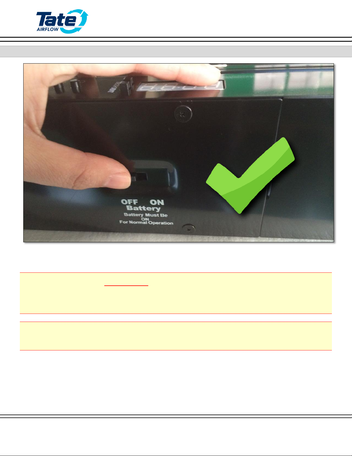
STEP 6: TURN THE BATTERY ON
Switch the Battery backup to the “ON” Position.
IT IS NECESSARY TO HAVE THE BATTERY IN THE
“ON” POSITION
DURING NORMAL OPERATION
IL EST NÉCESSAIRE D’AVOIR LA BATTERIE DANS LA POSITION ”ON” PENDANT LE
FONCTIONNEMENT NORMAL
Other manuals for SmartAire MZ Basic
1
Table of contents
Popular Air Conditioner manuals by other brands


Fujitsu
Fujitsu Inverter ASBA30JFC operating manual

Toshiba
Toshiba RAS-M10SMUV-E installation manual

Daikin
Daikin FXLQ20MAVE Operation manual

Hitachi
Hitachi RAS-E24CAK instruction manual

CIAT
CIAT Magister 2 Series Installation, Operation, Commissioning, Maintenance

Bestron
Bestron AAC6000 instruction manual


