Tatuus GB3 CHAMPIONSHIP User manual

TECHNICAL MANUAL (Part A)
TATUUS-MSV 023
Release 1.03 (27/02/2023)

3
CONTENTS
Contents........................................................................................................................................... 3
1General Information .................................................................................................................... 6
1.1 Releases ............................................................................................................................ 6
1.1.1 Release list:................................................................................................................. 6
1.2 Technical Contacts .............................................................................................................. 7
1.2.1 Chassis....................................................................................................................... 7
1.2.2 Engine ........................................................................................................................ 7
1.2.3 Gearbox ...................................................................................................................... 7
1.2.4 Electronic .................................................................................................................... 8
1.2.5 Tyres .......................................................................................................................... 9
1.2.6 Brakes ........................................................................................................................ 9
1.2.7 Dampers ................................................................................................................... 10
1.2.8 Seat belts – Fire Extinguisher ...................................................................................... 10
1.2.9 Fuel .......................................................................................................................... 10
1.3 Overview .......................................................................................................................... 11
1.4 Overall dimensions ............................................................................................................ 12
2Safety ..................................................................................................................................... 13
2.1 Chassis ............................................................................................................................ 13
2.1.1 Survival cell ............................................................................................................... 13
2.1.2 Front impact structure .................................................................................................13
2.1.3 Rear impact structure.................................................................................................. 15
2.2 HALO............................................................................................................................... 16
2.2.1 Installation procedure.................................................................................................. 16
2.2.2 Disassembly procedure............................................................................................... 23
2.2.3 HALO painting and certification .................................................................................... 25
2.3 Steering column ................................................................................................................ 26
2.4 Frontal Anti Intrusion Panel .................................................................................................26
2.5 Fuel cell ........................................................................................................................... 27
2.6 Fuel coupling .................................................................................................................... 27
2.7 Seat belts ......................................................................................................................... 28
2.8 Extractable seat ................................................................................................................ 29
2.9 Driver installation............................................................................................................... 30
2.10 Rain light .......................................................................................................................... 30
2.11 Wheel tethers ................................................................................................................... 30
2.12 Fire extinguisher................................................................................................................ 31
2.12.1 Introduction ............................................................................................................... 31
2.12.2 Precaution for use ...................................................................................................... 31
2.12.3 Homologation and intended use ................................................................................... 32
2.12.4 Installing the electrical control ...................................................................................... 32
2.12.5 Technical specifications............................................................................................... 33

Version 1.03
4
2.12.6 Maintenance .............................................................................................................. 33
2.12.7 Special situation ......................................................................................................... 34
2.12.8 Warranty ................................................................................................................... 34
3Chassis ................................................................................................................................... 36
3.1 Jacking ............................................................................................................................ 36
3.1.1 Front Jacking ............................................................................................................. 36
3.1.2 Rear Jacking.............................................................................................................. 36
3.2 Setup Tools....................................................................................................................... 37
3.3 Standard Set-up ................................................................................................................ 38
3.4 Weight and ballast ............................................................................................................. 39
3.4.1 Front ballast............................................................................................................... 40
3.4.2 Pedal box ballast ........................................................................................................ 41
3.4.3 Driver seat ballast....................................................................................................... 42
3.5 Cockpit............................................................................................................................. 43
3.5.1 Controls and procedures ............................................................................................. 43
3.5.2 Pedals ...................................................................................................................... 44
3.5.3 Brake bias ................................................................................................................. 48
8.1.1 Brake Bias Cable ....................................................................................................... 48
3.5.4 Screen / Deflector....................................................................................................... 50
3.6 Bodywork ......................................................................................................................... 51
Floor rubber pad ...................................................................................................................... 51
3.7 Geometry ......................................................................................................................... 52
3.7.1 Setup Adjustments ..................................................................................................... 52
3.7.2 Front pick-up.............................................................................................................. 53
3.7.3 Rear pick-up .............................................................................................................. 54
3.8 Steering geometry ............................................................................................................. 56
3.8.1 Geometry .................................................................................................................. 56
3.8.2 Track rod................................................................................................................... 56
3.9 Vertical stiffness ................................................................................................................ 57
3.9.1 Front......................................................................................................................... 57
3.9.2 Rear ......................................................................................................................... 57
3.10 Roll stiffness ..................................................................................................................... 58
3.10.1 Front......................................................................................................................... 58
3.10.2 Rear ......................................................................................................................... 58
3.11 Damping .......................................................................................................................... 59
3.11.1 Damper operation....................................................................................................... 59
3.11.2 Damper Curves.......................................................................................................... 60
4Wheels and Tyres..................................................................................................................... 61
4.1 Wheels............................................................................................................................. 61
4.2 Tyres ............................................................................................................................... 62
4.2.1 Pirelli Technical Prescriptions....................................................................................... 62
4.2.2 Pirelli front tyre ........................................................................................................... 64

Version 1.03
5
4.2.3 Pirelli rear tyre............................................................................................................ 66
5Aerodynamic............................................................................................................................ 68
5.1 General notes ................................................................................................................... 68
5.2 Front wing setting .............................................................................................................. 69
5.3 Rear wing setting .............................................................................................................. 71
5.4 Aerodynamic Reference setup ............................................................................................ 72
5.5 Ride Height sensitivity........................................................................................................ 73
5.6 Wings sensitivity................................................................................................................ 74
6Brake system ........................................................................................................................... 75
6.1 Master Cylinders ............................................................................................................... 75
6.2 Discs ............................................................................................................................... 75
6.3 Calipers ........................................................................................................................... 75
6.4 Pads ................................................................................................................................ 75
7Fuel system ............................................................................................................................. 76
7.1 Overview .......................................................................................................................... 76
7.2 Fuel Coupling ................................................................................................................... 76
7.3 Maintenance ..................................................................................................................... 77
7.4 Fuel safety........................................................................................................................ 77
7.5 Fuel Pump-Out Kit ............................................................................................................. 77
8Electric system......................................................................................................................... 78
8.1 Overview .......................................................................................................................... 78
8.2 Main switch....................................................................................................................... 78
8.3 Battery and Alternator ........................................................................................................ 79
8.3.1 Battery installation ...................................................................................................... 79
8.4 Powerbox ......................................................................................................................... 80
9Annexes .................................................................................................................................. 81
9.1 Tightening torque .............................................................................................................. 81

Version 1.03
6
1 GENERAL INFORMATION
1.1 RELEASES
Modifications from previous release are in red
1.1.1 Release list:
Version
Release
Date
Author
Notes
1.00
11/02/2022
Tatuus
Startup version
1.01
17/02/2022
Tatuus
1.02
12/05/2022
Tatuus
Added curves
1.03
27/02/2023
Tatuus
Updated paragraphs: 1.2.7, 2.2.3, 2.8, 2.10,
3.3, 3.6, 3.8, 6.4, 9.1

Version 1.03
7
1.2 TECHNICAL CONTACTS
1.2.1 Chassis
Tatuus Racing Srl
Via Juan Manuel Fangio, snc, 20045 Lainate (MI) - Italy
Tel: +39 039 6040828
Fax: +39 039 6041764
e-mail: info@tatuus.it
Web: www.tatuus.it
1.2.2 Engine
MSV
Bedford Autodrome
Thurleigh Airfield Business Park
Thurleigh
Bedford
MK44 2YP
Tel: +44 (0)1234 332400
e-mail: technical@gb-3.net
1.2.3 Gearbox
SADEV
6, rue des Grand’Montains
85110 SAINT PROUANT - France
Tel.: +33 2 51 664268
Fax: +33 2 51 664960
e-mail: sadev@sadev-tm.com

Version 1.03
8
1.2.4 Electronic
Brookfield Technology Centre Twentypence Road, Cottenham Cambridge CB24 8PS
Tel: +44 (0)1954 253600
Fax: +44 (0)1954 253601
Magneti Marelli Holding Spa Motorsport
via A. Borletti, 61/63
20011 Corbetta (MI) -Italy
Tel: +39 02 97227000
Fax: +39 02 97227570
Next Solution Snc
Via Belfiore, 31/D
23900 Lecco - Italy
Contact: Giuseppe Corti
Tel. +39 0341 289072
Fax +39 0341 370057
e-mail: mail@nextsolution.it

Version 1.03
9
1.2.5 Tyres
For General and Technical enquiries:
Natham Coleman
Tel: +44 (0)7752 825277
e-mail: natham.coleman.ex@pirelli.com
Pirelli Motorsport, Omega One
Collett, Didcot
Oxfordshire OX11 7AW
For Sales enquiries:
Protyre Motorsport
Tel: +44 (0)1782 411001
e-mail: shaun.chetwin@protyre.co.uk
1.2.6 Brakes
AP Racing
Wheler Road, Seven Stars Industrial Estate
Coventry, West Midlands, CV34LB
Tel: +44 (0) 24 7663 9595
Fax: +44 (0) 24 7663 9559
e-mail: sales@apracing.co.uk

Version 1.03
10
1.2.7 Dampers
ORAM
V.le Rasori, 2
20145 Milano – Italy
Contact: Andrea Pezzotta
Tel: +39 024989884
Fax: +39 0248003052
e-mail: info@oramitalia.com
UK service agent:
Ian Gardiner
I.G.Racing Limited
14 Harrowden Lane
Finedon
Northants
NN9 5NW
Workshop: 07967 300 537
Office: 01933 815 133
Website: http://www.igracing.co.uk/
1.2.8 Seat belts – Fire Extinguisher
OMP Racing
via Bazzano, 5
16019 Ronco Scrivia (Ge) - Italy
Tel. +39 01096501
Fax. +39 010935698
1.2.9 Fuel
Anglo American Oil Company Ltd
58 Holton Road
Holton Heath Trading Park,
Poole,
BH16 6LT
Contact: Anders Hilderbrand
Tel: +44 (0)1929 551557
e-mail: [email protected]

Version 1.03
11
1.3 OVERVIEW
Front track
1514 mm
Rear track
1485 mm
Wheelbase
2760 mm
Overall length
4539 mm
Overall width
Max 1750 mm
Overall Height
950 mm (from reference plane)
Weight
ND (refer to championship regulations)
Chassis
Composite Carbon fibre sandwich with Al/Nomex honeycomb,
FIA F4 (Ann.J Art.274) homologated
Bodywork
Composite Carbon fibre
Front suspension
Push-rod / twin damper / spring
Rear suspension
Push-rod / twin damper / spring
Springs
Helicoidal Eibach
Dampers
Bump and rebound adjustable
Brakes
AP Racing
Tyres
Pirelli
Wheels
OZ 13”x8” front – 13”x10” rear
Engine
Cosworth 2-litre Duratec
Exhaust
Aros marmitte
Electronics
ECU Cosworth SQ6 / GCU Magneti Marelli / Cosworth DB1HE Logger
Power system
Electronic Powerbox Next Solution
Gearbox
SADEV SL75 LW sequential 6 ratios
Gearshift
Magneti Marelli EGA
Steering wheel
Cosworth CFW277
Battery
DEKA ETX15L
Fuel cell
PREMIER FT3
Seat
Carbon fibre extractable shell (FIA standard).
Seat belts
OMP 6-points, 3” shoulder and lap straps, HANS compatible

Version 1.03
12
1.4 OVERALL DIMENSIONS

Version 1.03
13
2 SAFETY
This chapter enlists the Homologated Safety Devices, these parts cannot be modified or repaired without
the approval of MSV. See MSV Tecnical Manual (Part B) for details.
2.1 CHASSIS
2.1.1 Survival cell
The survival cell is the main safety and structural component of the car and it has been approved by the FIA,
great attention must be paid in checking for structural failure not later than two years after delivery from Tatuus
factory, and after each major accident. The Chassis must be checked and repaired by a centre authorised by
MSV. See MSV Tecnical Manual (Part B) for details.
2.1.2 Front impact structure
Front impact structure is a safety and structural component of the car (approved by FIA crash test), great
attention must be done in checking for structural failure not later than two years after delivery from Tatuus
factory, and after each accident. Front nose must be checked and repaired by a centre authorized by Tatuus
except for the following specified exceptions:
Front nose repair specification and procedure
Applicable requirements
The following procedure is applicable only when the damage is contained in the first 100mm from the nose tip
(715mm from the chassis bulkhead), all the other damages must be inspected by the manufacturer.
Replacement procedure
1. Spare nose tip is available, reference code is 16 14 01 003 002
2. Trace a line parallel to the chassis bulkhead 715 mm from the bulkhead, you should find the line 15
mm from the old nose tip junction.

Version 1.03
14
3. Cut off the nose tip forward the traced line
4. Using sandpaper on the outer surface, reduce the thickness of the crashbox by about 1mm for a length
of 15-25 mm (red area).
Attention must be paid to sandpaper the outer surface, at the depth of 1 mm you should find the
resin between first and second ply.
5. Use sandpaper on the new nose tip inner surface to produce a rough surface that will match the outer
surface of the crashbox.
6. Spread specific resin 3M 9323 over the junction surface, carefully respect the percentage between
resin and catalyst:
3M 9323 Mixing specification:
Resin
Catalyst
Weight ratio
100 g
27 g
Volume ratio
100 g
31 g
7. Position the new nose tip cleaning the excess of resin; new nose tip can be hold in position with high
temperature tape.
8. Cure the assembly on the oven following the specific temperature cycle for 3M 9323:
2 hours at 60°C.

Version 1.03
15
2.1.3 Rear impact structure
Rear impact structure is a safety and structural component of the car (approved by FIA crash test), great
attention must be paid in checking for structural failure not later than two years after delivery from Tatuus
factory, and after each accident. Rear impact structure must be checked and repaired by a centre authorised
by Tatuus. For 2018 a new rear impact structure has been introduced, part number 161804006. This is the
only rear impact structure permitted. Also see section 3.1.2 for additional information.

Version 1.03
16
2.2 HALO
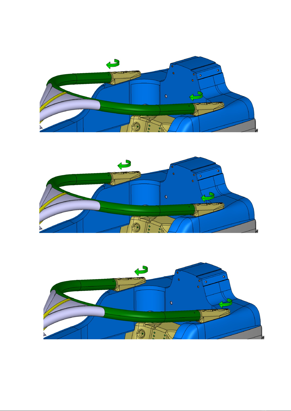
2.2.1 Installation procedure
General notes:
grey arrow: unscrew/screw but not tighten
green arrow: screw and tighten
When installing the HALO, apply on the bolts some water and oxidation resistant grease. For example, the
PETRONAS TUTELA Z2 grease is suitable for this purpose.
1. Insert the front fairing on the HALO center bar
2. Install the front bracket (28-01-010) on the HALO

Version 1.03
17
3. Fasten the HALO front fixing screw (24-01-017) and pin (24-01-016). Do not apply any tightening
torque.
4. Please note that the HALO front fixing screw (24-01-017) shall be on the left side and the HALO front
fixing pin (24-01-016) shall be on the right side.
5. Do not apply any tightening torque. Screw the HALO front fixing screw (24-01-017) until the screw’s
under-head gets in contact with the plane of the counterbore on the front bracket. At this point do not
apply any tightening torque but loose the HALO front fixing screw (24-01-017) one turn (counterclock-
wise).
6. Place the assembly obtained at point 3 on the chassis.
24-01-016
24-01-017

Version 1.03
18
7. Fasten the two shoulder bolts (24-01-033). Do not apply any tightening torque. Screw the bolts until
the screw’s underhead gets in contact with the plane of the counterbore on the HALO foot. At this point
do not apply any tightening torque but loose the bolt one turn (counterclockwise).
8. Fasten the two M12X55 bolts. Do not apply any tightening torque. Screw the bolts until the screw’s
underhead gets in contact with the plane of the counterbore on the HALO foot. At this point do not apply
any tightening torque but loose the bolt one turn (counterclockwise).

Version 1.03
19
9. Fasten the two M12X30 bolts. Do not apply any tightening torque. Screw the bolts until the screw’s
underhead gets in contact with the plane of the counterbore on the HALO foot. At this point do not apply
any tightening torque but loose the bolt one turn (counterclockwise).
10. Fasten the six NAS1307-16 bolts. Do not apply any tightening torque. Screw the bolts until the
screw’s underhead gets in contact with the plane of the counterbore on the front bracket. At this point
do not apply any tightening torque but loose the bolt one turn (counterclockwise).
Version 1.03
20
11. Tighten the two shoulder bolts 24-01-033. Do not tighten to target value one bolt first and then the
other. Apply the tightening torque gradually, keeping the balance on the two bolts. Target value is
51Nm.
12. Tighten the two M12X55 bolts. Do not tighten to target value one bolt first and then the other.
Apply the tightening torque gradually, keeping the balance on the two bolts. Target value is 51Nm.
13. Tighten the two M12X30 bolts. Do not tighten to target value one bolt first and then the other.
Apply the tightening torque gradually, keeping the balance on the two bolts. Target value is 51Nm.

Version 1.03
21
14. Tighten the six NAS1307-16 bolts. Do not tighten to target value one bolt first and then the other.
Apply the tightening torque gradually, keeping the balance on the four bolts. Target value is 51Nm.
15. Double check the tightening torque on each bolt starting from the two shoulder bolts (24-01-033), then
on the M12 bolts and finally on the NAS1307-16 bolts.
16. Tighten the HALO front fixing screw (24-01-017)
17. Position the front fairing and fix it with two button head bolts (UNI7380-TX-M5X10).
Table of contents
Popular Motorized Toy Car manuals by other brands

Kyosho
Kyosho V-ONE R4 instruction manual

marklin
marklin BR E 18 manual

Helion
Helion ROCK RIDER Owner's manual & technical information

Associated Electrics
Associated Electrics TEAM ASSOCIATED RC10B4 instruction manual

Anki
Anki Overdrive Product information guide

Reely
Reely Lightning 4WD RtR operating instructions


Tamiya
Tamiya QD Thunder Shot instruction manual

Associated Electrics
Associated Electrics RC8B4 manual

Jamara
Jamara Porsche 911 Carrera instructions

Serpent Model Racing Cars BV
Serpent Model Racing Cars BV f110 SF3 instruction manual

Jamara
Jamara Mercedes-Benz Antos 460657 Instruction

Jamara
Jamara 403084 Instruction