Taxan Super Vision IVm User manual
,.
.'~
.
:'.:',
- I •
:-,
\",,':'-;-.:''''!
\.,
-:
, '
••
,":"
':
':
c,
.:
• '
:."
••
, : <
. ." .
.•
'
,"",
," .
..
:"'<;/<':;,C;"
SERVICE
"MANUAL
.
.\
.'
.
r
i,
.
. I
I
..
i .
.1
.
12"
'.
COLOR DISPLAY'
SUPER
VISION
DOtlI
DrYl~M
.
, ' . '. , . . TM
-SUPER
VISION
fbJ3JillJlflnlJ{][I1J
, .
IMPORTANT
SERVICE
SAFETY
;
Operatic.n,of monitor outside
of
cabinet
or
with back removed
involves a shock hazard. Work
on
these models should only
be
performed
by
those who arll thoroughly familiar. with prccau-
..
tions neCessary when working on high voltage equipment
•.
Exercise care
when
servicing this chassis with power applied.
Many 8 plus and high voltage
RF
terminals are exposed which.
if
carelessly contactlld. can cause serious shock
or
result
in
dam-
age
to
the
chassis. Maintain interconnecting ground lead con-
. ncetions
bet.ween
chassis.escutcheon and picture tube dag cluster
when operating chassis. The
+8
Adj.Control in this monitor is
sealed
in
order
to.protect
the user from X-ray irradiation.The
...
'
B Adj.Control should
oot
normally have
to
be
adjusted.But
iC
it
is
..
cr
Ie
it
is replaced due to damage.check the +B voltage to as-
sure that.
it
is within specifications
after
adjustment.Then seal
this control according
to
the manuCacture's specification.
Certain H Y failures can increase X-ray radiation. Monitors
should
not
be
operated with HYlevels exceeding the
specified
rating
for
th«;
chassis
type. The maximwn operating H Yspecified
for
the
chassis used
in
these
monitor
is
22
KV
at
zero beam current with a line voltage
of
120Y
AC.
Higher voltage may also increase possibility of failure
in
H·Ysupply.
It
is
important
to
maintain
specified values
of
aU
components'
in
the horizontal and high voltage circuits and anywhere else in
the
monitor
that
could cause a rise in high voltage
or
operating
supply voltage.No changes should
be
made
to
the original de-
sign
olthe
monitor.Components shown in the shaded areas od
the schematic diagram
and/or.
identified
by
&. *
in
the re-
placement.
parts
list should
be
replaced only with exact Factory
recommended replacement
parts.
The use
of
unauthorized
substitute
parts_ may create a shock.
fire.X- ray
radiation.or
other
hazard.
To determine the presenCe
of
high voltage.use an accurate.high
. impedance.H Ymeter connected between
the
second anode leitd
and the CRT dag
groundin~
device_When servicing the High
Yoltage System.remove
static
charge
e~om
it
by
connp.cting a
10K
ohms resistor in series with an insulated wire (such as a
test probe) between picture tube
dag
and 2nd anode lead.
(AC,
line cord disconnected
Crom
AC
supply.)
The picture tube. used in this·
monitor
employs integral implo-
sion protection.Replace with a tube at the same type number
,Cor
continued
safety.Do
not
IiCt
picture tube by the neck.Han-
dIe
the picture tube only when wearing shatter-proof goggles
and
after
discharging the high voltage completely.Keep l)ttiers
withoutshafter-proofl goggles away.
When
removing springs
or
spring mounting
parts
from the
chassis.shatter-proof gottgles
must
be worn.Keep others without
shatter-proof
goggles away.
••••
e'
SAFETY INSPECTION • •
lor
e'
•
Before returning the monitor to
the
user. per
Corm
the following
safelY checks:
INFORMATION
Super Vision IV/IVM
Super Vision
640/630
• • •
...
PROTECT YOUR CUSTOMER • • • • •
Llnspect all lead dress
to
make certain
that
leads
are
not
pinched and
that
hardware
is
not lodged between the chassis
and, other metal
parts
in the monitor.
2.Replace all protective devices such
as
non·metaUic control
knobs.cabinet back.l\djustment covlu·s.shields.etc.
3.To
be
sure tllat no shock
hazarc!exists.a
check
for the pres·
enee
oC
leakage current should
be
made
at
eech exposed
metal'
part
having a return
path
to
the chassis(jack.cabinet metal.
screw heads. knobs.shaftli.etc.)in the following manner.
Plug the
AC
line cord directly into a 120Y
AC
receptacle.(Do
not use an Isolation Transformer during these checks. )All
tP.Sts
must be repeated with' the
AC
Hne
cord plug connections.
l'e~
versed.
(If
necessary.a non-polarized
AC
adapter
plug must
be'
used for .the purpose
of
completing these checks.
Do
not other-
wise operate the monitor with an
adapt,.r.)
Ie
available.measure leakage current using an accurate leakage
current tester.Any reading oCO.35MA
or
more· is excessive and
indicates
II
potential shock hazard which must
be
corrected
be-
Core
returning the monitor
to
the owner.
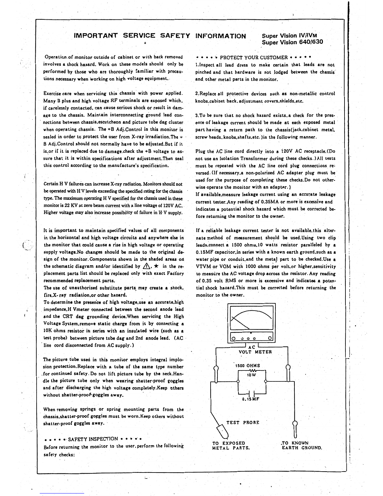
If
a reliable leakage current tester is not available.this alter-
nate method
of
meesurement
sho~I1d
be
used.Using two clip
leads.connect a 1500 ohm:l.l0
watts
resistor paralleled
by
a
0.15MFeapacitor.inseries
with a known
earth
ground.such as.a
water
pipe
or
conduit.and the meta}
part
to
be checked.
Use
a
VTYM
or
YOM with 1000 ohms per
volt.or
higher.sensitivity
to measlire the
AC
voltage drop across the resistor.
Any
reading
of
0.35 volt RMS
or
more is excessive and indicate&a
poten~
tial
shock hazard.This
must
be
corrected before returning the
monitor
to the own.er. !
!
. ,
0)
a 0
_-----'ACL------,
VOLT
METER
\.
I
1500
OHMS
lOW
O.ISMF
TEST
PROBE
I
TO
EXPOSED .TO KNOWN
METAL
PARTS_
EARTH
GROUND. I
, .
IMPORTANT
NOTICE
FOR
SERVICE PERSONNEL BEFORE SERVIC'ING
PLEASE READ BEFORE ATTEMPTING SERVICE
1.' While
the
monitor
isin
operation, do
not
attempt
to
connect
or
disconnect any wires.
10',
sis 2. Make sure
the
power cord is,disconnected before replacing any components
in
the monitor.'
rol
3. When
the
power
is
on, do
not
attempt
to
short any portion
of
the circuit. This shorting may
cause damage
to
the
transistors
in
the monitor.
as·
lal
4.
When servicing
the
H;
V.
area,
be
certain tl:lat
the
C.
R~
T anode is.safely discharged
to
ground
Ill. before removing
the
anode cap.
)0
5. Caution, must be exercised
when
servicing this monitor.
;I.S
,The regulator has no current Iimitinganq even a momentary short
of
an
output
voltage could
~e-
cause destruction
of
the
pass transistors.
be
!r-
gt'
i
le-
I ,
I
tr
..
i
ip
I
I '
a
a
"'
i,
a
ly
Ig
~-
Ie
/
....
- 1 -
IProduct.Outline
'I
This model
is
a 12-inch color display monitor,
used
for a personal computer terminal.
Its
input
is
TIL
s~parate
signals. The input terminal
is
an
8-pin
DIN
)ack.
Specifications
CAT
Signal
input
'
Power Supply
Wattage
Cabinet
Dimensions
Weight
Scanning
frequency
OPERATION
12-inch
type
with
646.8
mm R
• Facing: Non-glare' face 'plate
Facing: Glare face plate
• Screen phosphor:
630/640
Separate
R,
G,
B,
I,
H, V
•
R,
G,
B,
I:
."
Positive
• Sync: Positive or negative
Local commercial
power
supply
SOW
Plastic
630/640A,
B,
S
,
630/640U,
J
B22
(Short persfstence)
322
(W)
x
309
(H)
x
372
(D)
mm
.
12
kg
24.S
kHz (Horizontal)
54.3
Hz (Vertical)
1.
Plug
the display
and
the computer into
AC
outlets.
2. Set
the
color mode switch
on
the
rear
panel.
3. Connect the signal input terminal
sm
the
rear
panel
to
the computer using the optional cable.
4. Turn on display monitor
and
computer.
5.
The
green
power indicator (just
above
tbe power'switch), lights, then the
CRT
·screenbrightens.
(There
may
be
9haracters displayed.)
6.
After the monitor warms up,
set
brightness
and
contrast if necessary.
7. Position of the image, image
area,
and
focus
are
preset at
the
factory,
so
you
don't have
to
adjust
these. Depending
oriyour
computer, image width, height,
and
position may differ from
the
stan-
dard settings',
In
such a
case,
reset
as
necessary (controls
are
on
the
rear panell.·
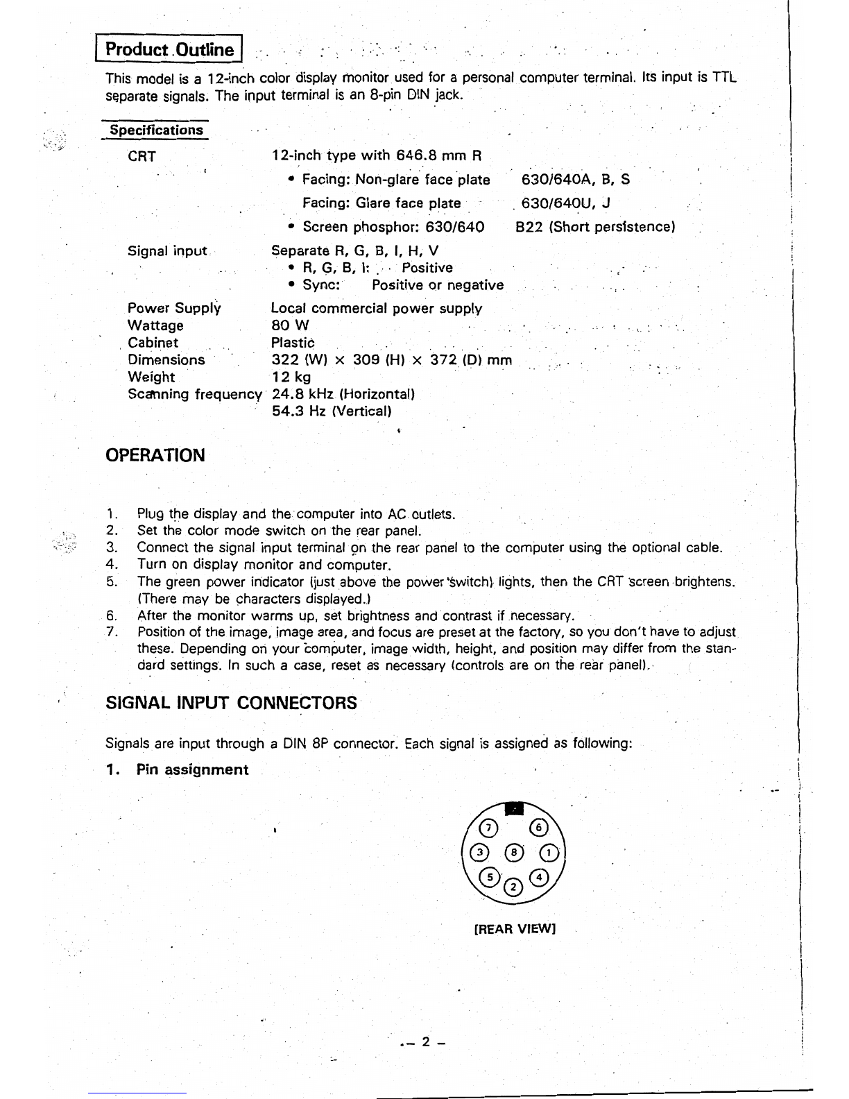
SIGNAL INPUT CONNECTORS
. .
Signals
are
input through a DIN
8P
connector.
Each
signal
is
assigned
as
following:
1. Pin
assignment
[REAR
VIEW]
.-
2 -
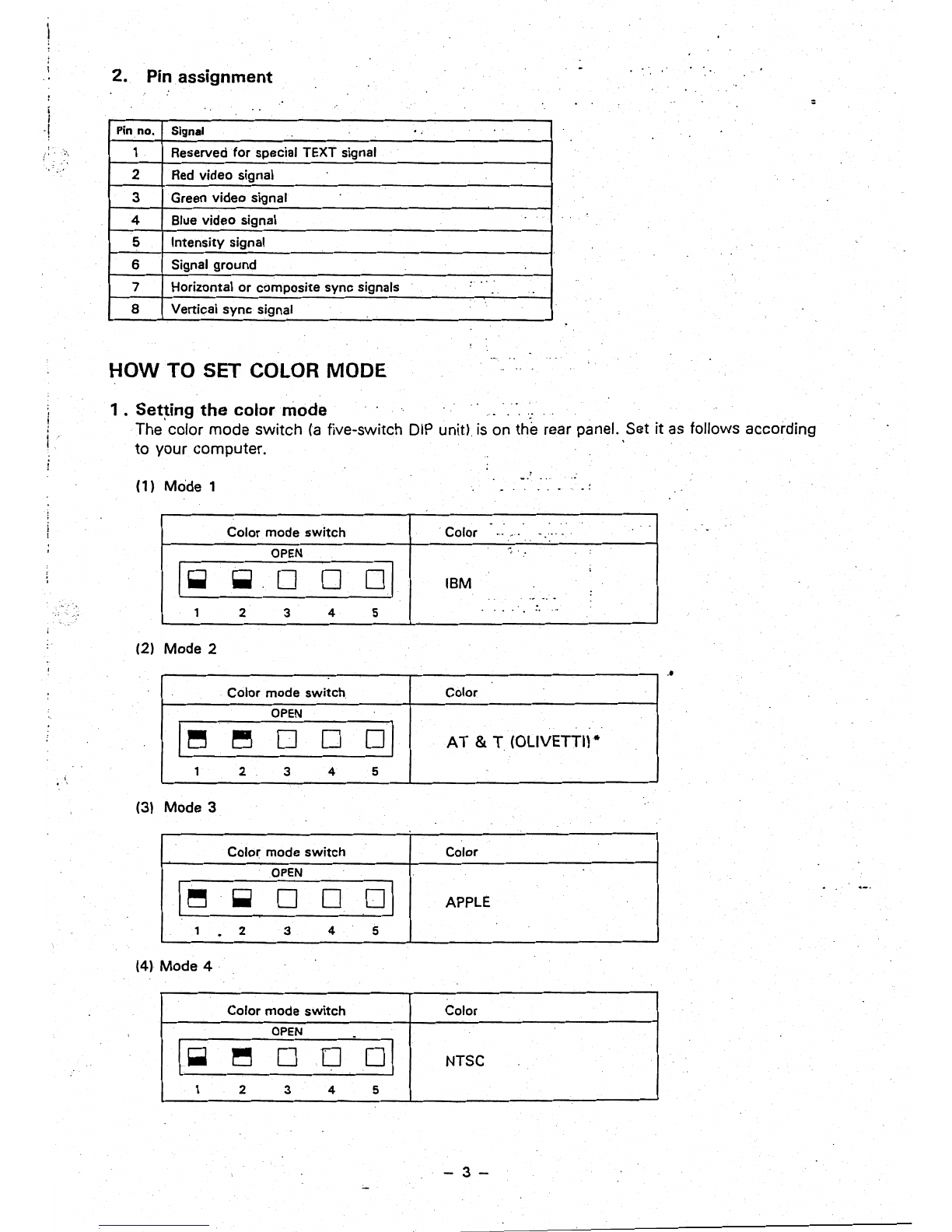
2.
Pin
assignment
:
i
.!
Pin
no.
Signal
1 Reserved
for
special TEXT signal
2
Red
video signal
3 Green video signal
4 Blue video signal
5 Intensity signal
6 Signal ground .. .
7 Horizontal
or
composite sync signals
~.
..
8 Vertical
sync
signal
HOW
TO SET COLOR MODE
1 .
Set~ing
the
colarmade
.;
The
color mode switch
(a
five-switch
DIP
unit)
is
on the rear panel. Set it
as
follows according
to your computer.
(1) Mode 1
.
Color mode
switch
.Color ...
~'.
. .
..
' .
I- OPEN ,
~
0 0
oj
IBM :
.,.
~.
. .
..
..
1 2 3 4 5
(2) Mode 2
..
Color mode
switch
Color
OPEN
AT
& T (OLIVETTI)*
I~
~
0 0
01
1 2 3 4 5
(3) Mode 3
Color mode
switch
Color
I~
OPEN
01
~
0 0 APPLE
1 . 2 3 4 5
(4l
Mode
4·
Color mode
switch
Color
I- OPEN .
~
0 D
01
NTSC
1 2 3 4 5
-3-

•
Note
-ADDENDUM
fgr
AT&T
PC6300
and compatibles
630/640
E,
U.
A,B.
S are factory-set to use
with
IBM PC/XT/AT
Of
compatibles. You may need the following adjustment
.in
order
to
obtain maximum performance in display when you use withAT&T PC6300. PC6300
PLUS
computer
and
compatibles.
,.
Curl at top Turn H.
HOLD
counter-clockwise.
Turn
HoPOSI
clockwise.
D
.2. Small screen size
al
Horizontal size Turn
H.
SIZE
c;ounter-clockwise.
bl
Vertical size Turn
V.
SIZE
counter-clockwise.
CJ
3. Characters missing
at
top
Turn
V.
HOLD
clockwise
..
-4-
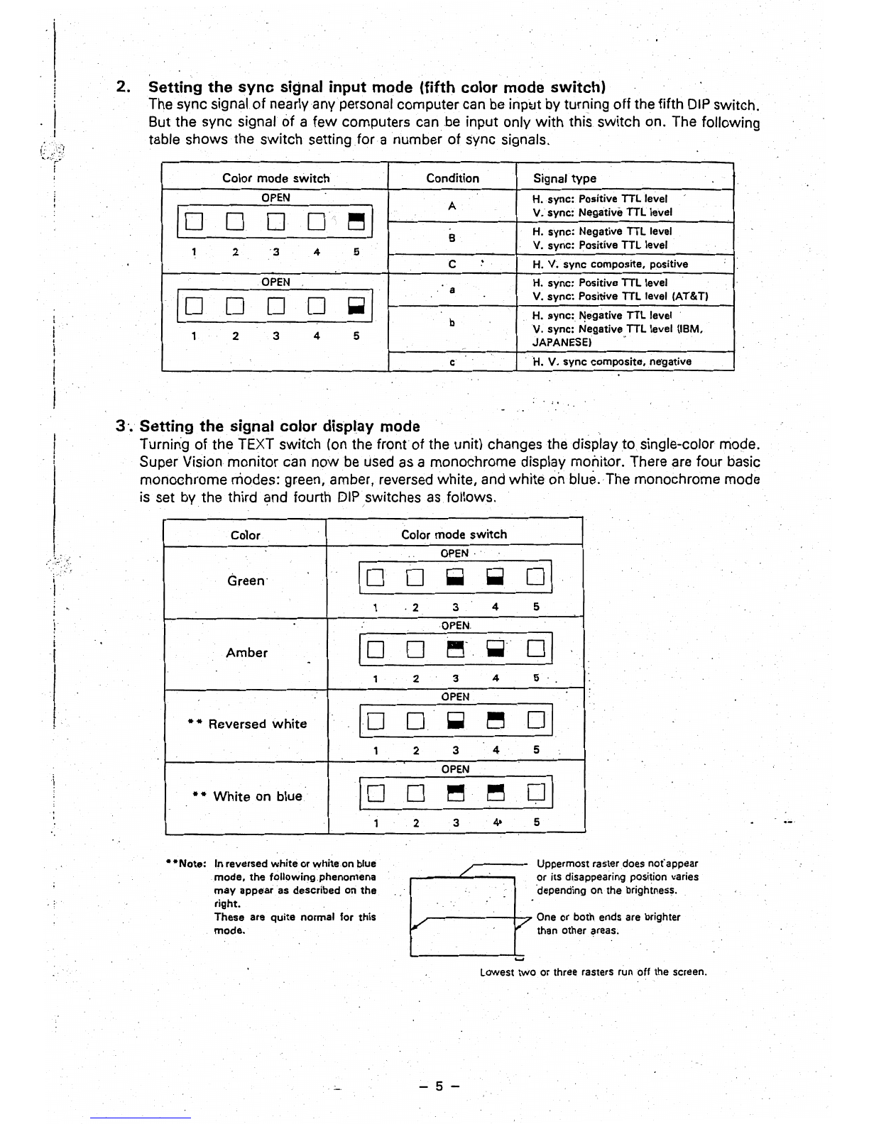
2.
Setting
the
sync
signal input
mode
(fifth color
mode
switch)
The sync signal of nearly any personal computer can
be
inp~t
by turning off the fifth
DIP
switch.
But the sync signal
of
a few computers can be input only with this switch on. The following
table shows the switch setting
for
a number of sync signals.
Color mode switch Condition Signal type
OPEN
H. sync: Positive TTL level
A V. sync: Negative TTL level
10
0 D 0
~I
H. sync: Negative TTL level
8 V. sync: Positive TTL level
1 2 3 4 5 .
C H. V. sync composite, positive
OPEN
H. sync: Positive TTL level
a
V.sync:
Positive TTL level (AT&T)
10
0 0 0
~I
H. sync:
~egative
TTL level
b
V.
sync: Negative,TTL level (18M,
1 2 3 4 5 JAPANESE)
e'
c
H.
V.
sync
composite. ne'gative
3
'.
Setting
the
signal color display
mode
Turnin'g
of
the TEXT switch
(on
the
front
of the unit) changes the display
to
single-color mode.
Super Vision monitor can nowbe
used
as
a monochrome display monitor. There are four basic
monochrome modes: green, amber, reversed white,
and
white
on
blue.
The
monochrome mode
is
set by the third and fourth DIPswitches
as
follows.
, ' I
,
color
Color
mode
switch
OPEN, '
I Green'
10
D
~
~
01
1
,2
3 4 5
r 10 0
OPEN
01
i
~.,
~-
Amber
3 4 5
I -1 2
\0
OPEN
01
l
~
,
••
Reversed
white
0 ~
~
1 2 3 4 5
OPEN
*.
White
on
blue
10 0
~
~
01
1 2 3 4- 5
-
-Note:
In reversed whiteor white on blue Uppermost raster does nofappear
/'
mode,
the
following phenomena or its disappearing position varies
may appear
as
described
on
the 'depending on the brightness,
right.
These are quite normal for this
One
or both
ends
are
brighter
V
mode. v than other
areas
.
......
lowest
two or three rasters run
off
the screen.
- 5 -
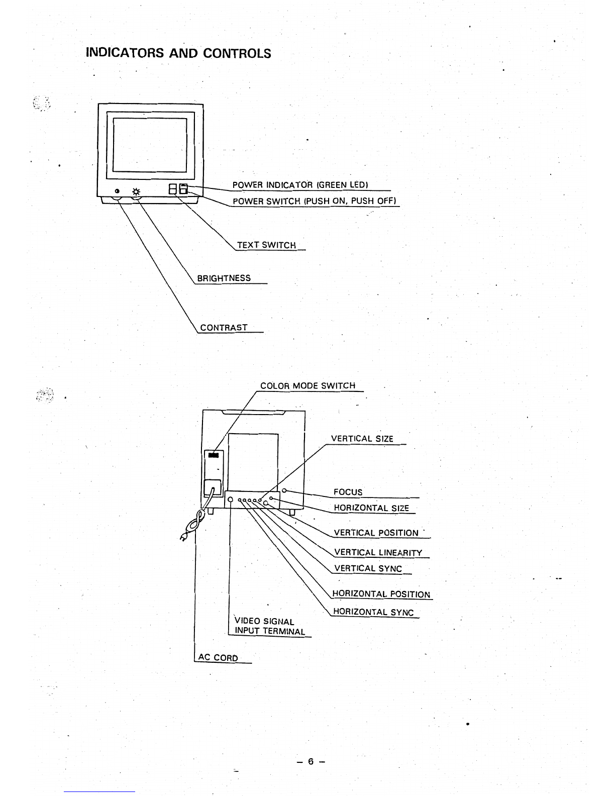
INDICATORS·
AND
CONTROLS
POWER
INDICATOR
(GREEN
LEDI
POWER
SWITCH (PUSH ON. PUSH
OFF)
TEXT SWITCH
BRIGHTNESS
CONTRAST
COLOR
MODE SWITCH
VERTICAL
SIZE
FOCUS
. HORIZONTAL
SIZE
VERTICAL
POSITION·
~
'"
""'VERTICAL
LINEARITY
•
'\:
VERTICAL SYNC
.•
'.'
~ORIZONTAL
POSITION
.
'"
HORIZONTAL SYNC
VIDEO SIGNAL
INPUT TERMINAL
AC
CORO
- 6 -

(
..
I
I
.
I
ADJUSTING THE DISPLAY
;
1. H. SIZE
If the horizontal size
of
the screen image
is
too short or too long. adjust the
H.
SIZE
control for
the correct
size.
(See illustration
1.)
2.
V.
SIZE
If the vertical
size
of
the screen image
is
too short or too long, adjust
theY.
SIZE
control for the
correct size.
(See
illustration
2.1
.'
3. H.
POSt
If the screen image shifts horizontally. adjust the H.
pas!.
control fora correct image.
(See
illustra-
tion
3.)
.
4.
V.
POSI.
·If the
scree~image
shifts vertically, adjust the
V.
POSI.
control for a correct image.
(See
illustration
3.1
5. H. HOLD
If the screen image has horizontal stripes or if
the.
image moves left or right, adjust the
H.
HOLD
control for a clear stable image.
(See
illustration
4.1
6,
V.
HOLD ,
If the screen image moves or overlaps vertically, adjust the V. HOLD control for
astable
image.
(See
illustration
4,1
7.
FOCUS
Adjust the focus· for the sharpest image.
(See
illustration
6.1
8. V. LIN.
Adjust the
y.LlN
control so
the
height of characters
is
even over the whole screen.
(See
illustration
7.1
9.
CONTRAST
Turning
the.
CONTRAST control clockwise increases the contrast, turning it counterclockwise
.decreases the contrast.
10.
BRIGHT
Turni'ng the
iRIGHT
control clockWise
makes
the screen brighter, turning it counterclockwise makes
it darker.
11.
SUB-CONTRAST
To adjust the subcontrast, display a screen of characters then turn the
BRIGHT
control to the
clic~
stop position, and the CONTRAST control fully clockwise.
Now
adjust the SUB-CONTRAST control
(VR
140) to the position just before the characters ·become saturated
..
12.
H. CENTER
To adjust horizontal centering turn the
BRIGHT
and the CONTRAST controls fully clockwise with
nothing displayed on the screen. Then adjust the
H.
CENTER
VR
(R742) so that the raster
is
centered
on the screen.
-
7-

13.
SIDE-pee
Depending on computer models with which display monitors
are connected, pincushion or
barre'!
distortion appears on the
right and left edge portions of their screen areas
as
shown
in
Fig.
1
..
The distortion
on
the right and left screen portions
can
be
minimized by turning the "SIDE-PCC" potentiometer,
clockwise or counter-clockwise, for optimum distortion-
correction results.
1\
J\
I \ I \
I ,
r I I I
\ I \ I
\ I
" "
:-. . .
~
•
- 8 -
I
f
" ,
, ,
!
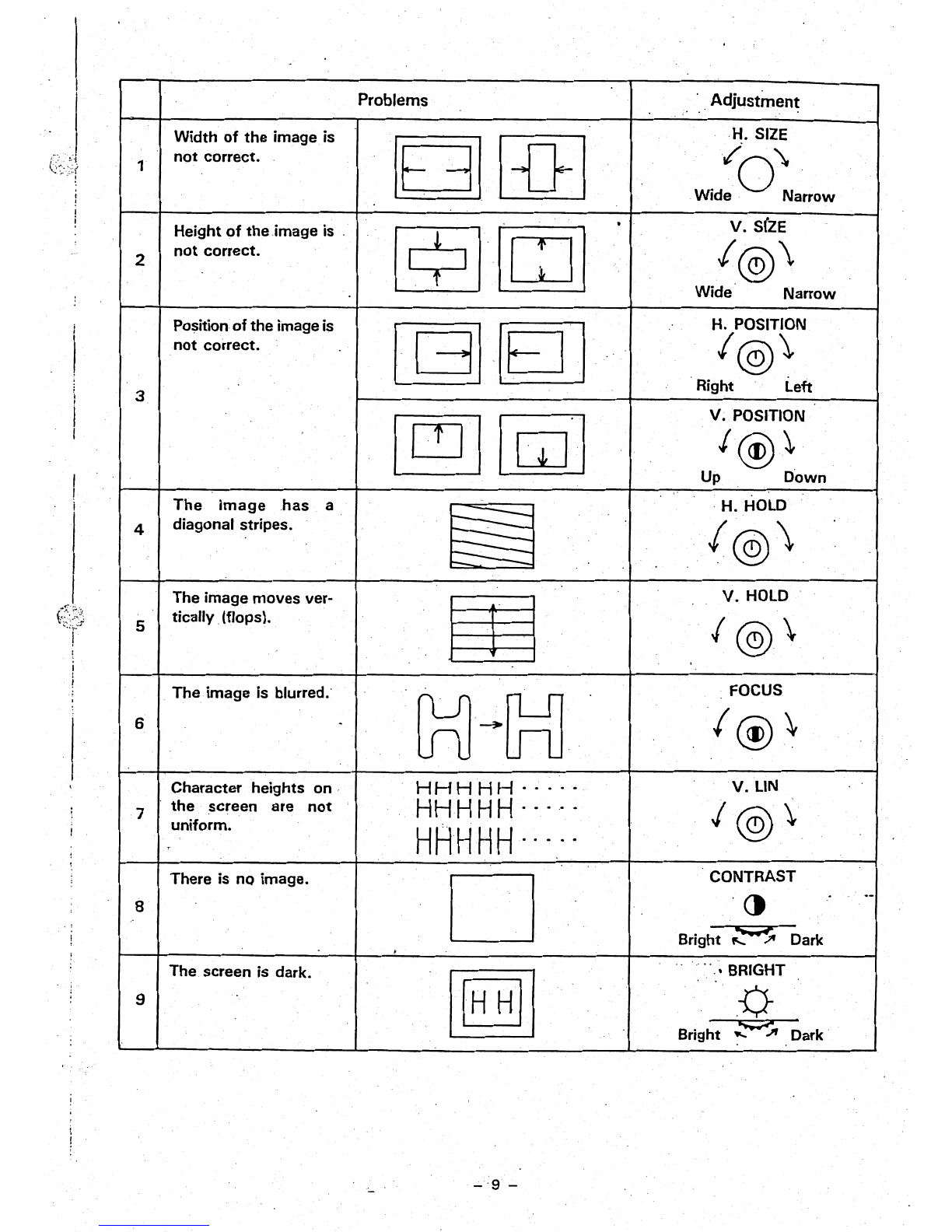
Width
of
the image,is
not
correct.
1
Height
oftheimage
is '
not
correct.
2
Position
of
the image is
not
correct.
3
The
image
,has,
a
diagonal stripes.
4
The image moves ver-
tically,(flops).
5
The image is blurred. .
6
Character 'heights
on,
the
screen are
not
7
uniform.
c
There is
nQ
image.
8
The screen is dark.
9
Problems
BJ
BlJ
[2J[C] .
~·lEIJ
[gTI
[E5J
§§
m
~~G=l1
HH
H H H
.....
HH
HHH
.....
HHHHH··
~,"
D
, ,
I~II
'
,Adjustmen~
, ,
,H. SIZE
w~:O~a"ow
V.
S(ZE
I@\
Wide Narrow
H.
POSITION
/@\
Right Left
V.
POSITION
I
@)
~
Up
Down
,H.
HOLD
I@\
V.
HOLD
I
@\
FOCUS
I@\
V.lIN
I@\'
'CONTRAST
.
.-
ct
Bright ;::-s Dark
"
"','
BRIGHT
P-
Bright
.z-A
Dark'
..;.'9 -
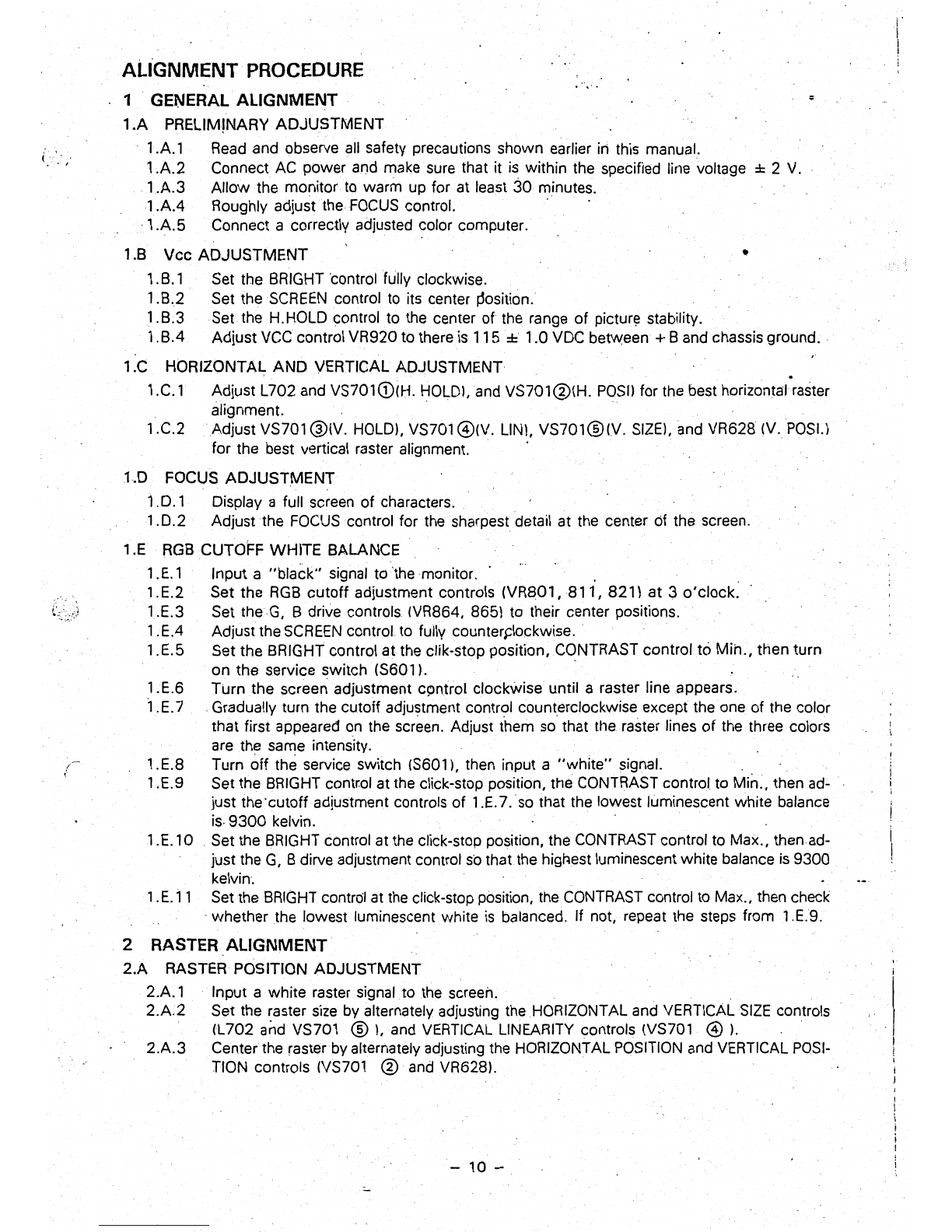
ALIGNMENT PROCEDURE
;
1 GENERAL ALIGNMENT
1
.A
PRELIMINARY ADJUSTMENT
.
1.A.l
Read
and
observe
all
safety precautions shown earlier iii this manual.
1.A.2 Connect
AC
power
and
make
sure
that it
is
within the specified line voltage ± 2
V.
1.A.3 Allow the monitor
to
warm up for at least
30
minutes.
1.AA
Roughly adjust the
FOCUS
control.
·1.A.5
Connect a correctly adjusted color computer.
1.B Vec ADJUSTMENT •
1.B.1· Set the
BRIGHT
'control fully clockwise.
1.B.2 Set the
SCREEN
control
to
its center
~osition.
1.B.3
Setthe
H.HOLDcontrol to
the
center
of
the range of
pictur~
stability.
1.
BA
Adjust vcecontrol VR920 to there
is
115 ±
1.0
VOC
between +Band chassis ground.
1.C HORIZONTAL AND VERTICAL ADJUSTMENT .
1.C.1 Adjust L702 and VS701G)(H. HOLDl,and VS701@(H.
POSIl
for
the
best horizontal raster
alignment. " .
1.C.2 .Adjust VS701 @(V. HOLD),
VS701
@(V. LIN), VS701@(V. SIZEl,and VR628
(v.
POSI.)
for
the best vertical raster alignment.
1.D FOCUS ADJUSTMENT
1.
D.
1 Display a full screen of characters
..
1.0.2
Adjust the
FOCUS
control for
the
sharpest detail
at
the center of the screen.
1.E
RGB
CUTOFF WHITE BALANCE
1.E.1 Input a
"black"
signal to 'the monitor. . . .
1.E.2 Set the
RGB
cutoff adjustment controls (VR801,
811,
821)
at
3 o'clock.
1.E.3 Set
theG,
B drive controls (VR864, 865) to their center positions.
1.EA
Adjust the
SCREEN
control to fully counters:lockwise
..
1.E.5 Set the BRIGHT control
at
the clik-stop position, CqNTRAST control t6 Min., then turn
on the service switch (S601)'
1.E.6 Turn
the
screen adjustment cpntrol clockwise until a raster line appears.
1.E.7 .Gradually turn the cutoff adjustment control counterclockwise except the one of the color
that first appeared on the screen. Adjust them
so'
that
the
raster lines of
the
three colors
are the same intensity.
1.E.8 Turn off the service switch (S601), then input a
"white"
signal.
1.E.9 Set the
BRIGHT
contr.ol
at
the
click-stop position, the
CONTRAST
control
to
Min
..
then ad-
just the'cutoffadjustment controls of 1.E.7.so that the lowest luminescent white balance
is·
9300
kelvin.
1.E.l0
Set the
BRIGHT
control at the click-stop position, the
CONTRAST
control to Max., then ad-
just the
G,
8 dirve adjustment control
so
thatthe highest luminescent white balance
is
9300
kelvin.
1.
E.l1
Set
the
BRIGHT
control
at
the
click-stop position,
the
CONTRAST
control to Max., then check
..
whether the lowest luminescent white
is
balanced.
If
not, repeat the steps from 1.E.9.
2 RASTER ALIGNMENT·
2.A
RASTER POSITION ADJUSTMENT
2.A.l
. Input a white raster signal to
.the
screen.
."
2.A.2
Set the raster
size
by
alternately adjusting the HORIZONTAL
and
VERTICAL
SIZE
controls
(L702 and VS701
®),
and
VERTICAL
LINEARITY
controls (VS701
@).
.
2.A.3
Center the raster
by
alternately adjusting the HORIZONTAL
POSITION
and
VERTICAL
POSI-
TION contrQls
(VS701
®
and
VR628l.
-
10
-
I
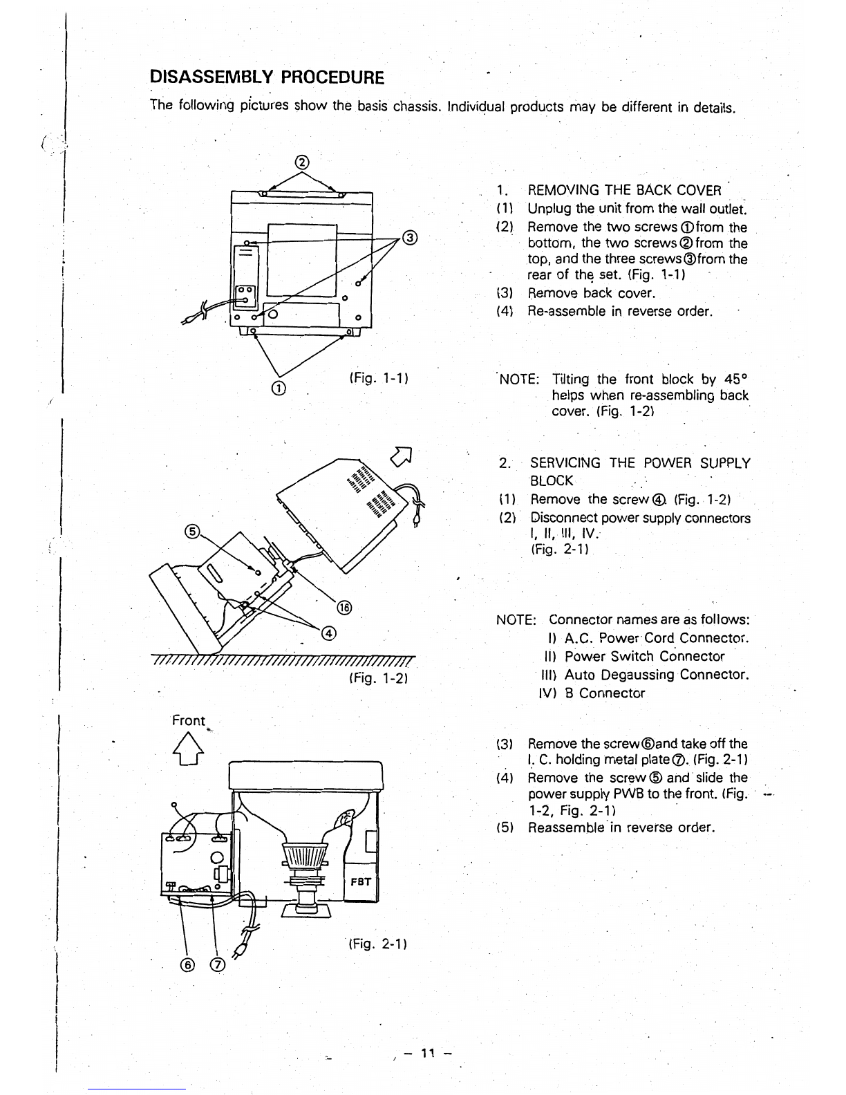
DISASSEMBLY
PROCEDURE
The following pictures
show
the basis chassis. Indiviqual products
may
be different in details.
(
.'
/
1. REMOVING THE BACK
COVER
{1) Unplug the
unitfrom
the wall outlet.
(2) Remove the
two
screws
(j)from
the
bottom,
the
two
screws®from the
top, and the three
screws@from
the
rear
of
th~
set. {Fig. 1-1}
(31
Remove
back
cover.
(4)
Re-assemble in reverse order.
o
(Fig. 1-1) NOTE: Tilting the front block by 45°
CD
helps
when
re-assembling back
cover. (Fig. 1-2)
2. SERVICING THE POWER SUPPLY
BLOCK
(1) Remove the screw@. {Fig. 1-2)
(2)
Disconnect
power
supply Connectors
I,
II, III, IV.
(Fig.
2-1).
NOTE: Connector names are as
follows:
I)
A.C.
Power'Cord
Connector.
II)
Pow€r
Switch
Connector
III)
Auto
Degaussing Connector.
(Fig. 1-21 IV) B
Connector
Front
(3)
Remove the
screw®and
take
off
the
{]'
I.
C.
holding metal plate
<£>.
(Rg. 2-1)
(4)
Remove the
screw@
and slide the
power
supply PWB to the front. (Fig
...•
,
1-2, Fig. 2-1)
(51
Reassemble'in
reverse order.
FBT
(Fig. 2-1)
-
11
-
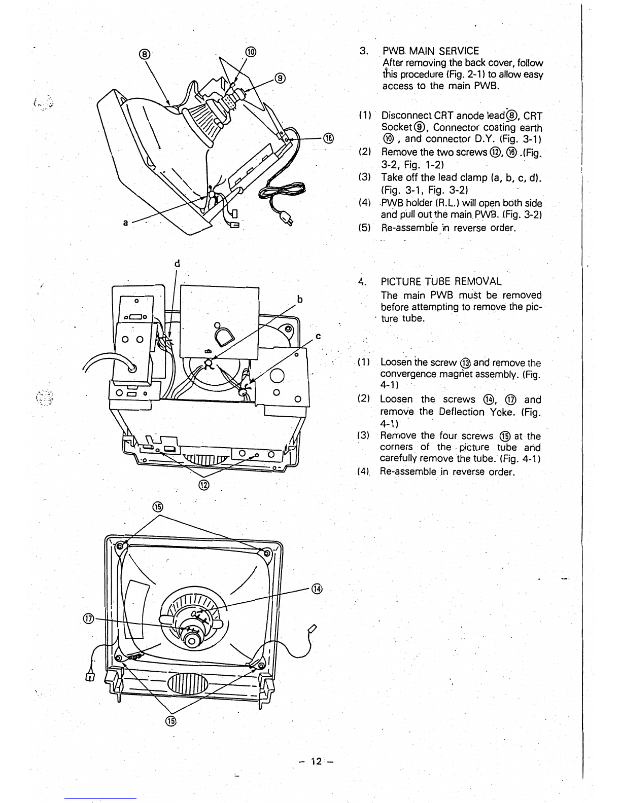
3.
PWB
MAIN
SERVICE
.
~fter
removing the back cover, follow
this procedure
(Fig.
2-1) to allow
easy
access to the main
PWB.
(1)
. Disconnect
CRT
anode lead@,
CRT
Socket®, Connector coating earth
@,
and connector D.Y.
(Fig.
3-1)
(2)
Remove the
two
screws@,@.(Fig.
3-2, Fig. 1-2)
(3) Take
off
the lead clamp
(a,
b, c, d).
(Fig. 3-1, Fig. 3-2)
.
(4)PWB
holder
m.LJ
will open
.both
side
and
pull out the
main.
PWB.(Fig, 3-2)
(5)' Re-assemble in reverse order.
d
4.
PICTURE
TUBE
REMOVAL
The main PWB must
be
removed
before attempting to remove the pic-.
.
turetube.
c
.
(1
)
Loosen
the
screw @ and remove the
convergence magnet assembly.
(Fig.
4-1
)
(2) Loosen the screws
@,
@ and
remove the Deflection Yoke. (Fig.
4-1)'
.
(3) .Remove the four screws ® at the
corners of
the·
picture tube and
carefully remove the tube.'
(Fig.
4-1)
(4).
Re-assemble.in reverse order.
®
®
-
12
-
,.""--
~."';::;
\
.
~;':,~
';
~-----
1./,."
----'-------_....
;,;;
POWER
INPUT 0 ,
-I
VOLTAGE 5yt1T-
CHING
REGULA
TOil
TO
H.
O~TPUT
CIRCUIT
I----.~--
TO
H.
DRIVE
CIRCUIT
AUTO DEGAUSS
THSOI.
I
VIDE
INPU
0
T
R"-
G
B_
\
I
ICSOl,OS20
COLOR
INTERFACE
.IC
tOl
I C
J
L L
TO
H.
FREO.
CIRCUIT
flCUIT
R.
BUFfER
0101
I
I
G.
BUFFER
0131
J
r-
.r-
RED
OUTPUT AMP•. -
0851.0854
GREEN
OUTPUT -
AMP.
0852.
0855
I--
;~
>
+
~
I
I
)
I.
I
I
I
I
I
I
CRT ,
)
.....
W
I'
--
1"-
0140.0141
CONTRAST CON·
TROL
VR141
SYNC. I
JPUT
H
lrHN
_ SYNC.
,. MIXER
V
...
IC102.
J
INTERLACING CONTROL
VR301,
IC30t,
IC302
J
B.
BUFFER
0161
L
t--
BRIGHT
CONTROL
VR140
0171
=t
BLANKING CIRCU!T
0143
.'
BLUE
OUTPUT AMP.
0853,01156
SIDE·PCC
CONTROL· N:i
VR640
PCT
H. OUTPUT
0702
t-
U
200
V
6 Vrms
17'17:
z
w
w
a:
(J
~
'--
.
III
III
::l
u
0
u.
1
500
-900
V
5'.6
kV
~
20
kV
HV
75V
AUTO
DEGAUSS
COIL
V. OUT CIRCUIT
H. SYNC.
PULSE
WIDTH
REGULATOR
\
ICl03
._.
__
. J -H.
DRIVE
0701
fBT
-.9
'H.
OEFLE,...",·
....
u ,.._.f
13V
~
VIDEO AMP.
CUlT
V.
FREO
CIRCUIT
L--.
BLANKING
OUTPUT
H.
SYNC.
IN
V.
SYNC. IN
H.FREO
AFC
HIGH
VOLTAGE.
PROTECTION
V.
FREO
~
V.
OUTPUT0601,
060~
~
V.
DEFLE
t
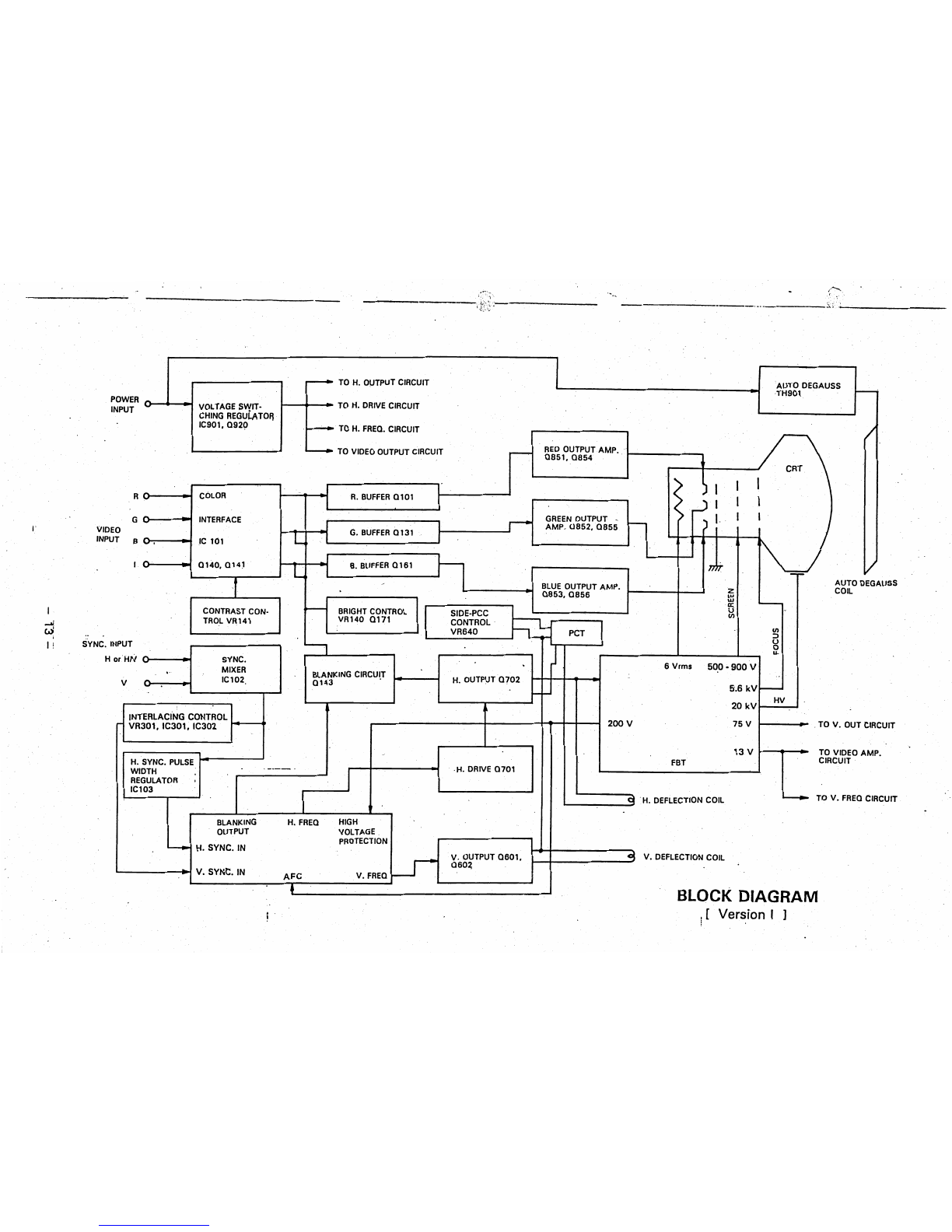
BLOCK
DIAGRAM
\[
i Version I ]

...
---.'
\.:
:
TO
H. OUTPUT CIRCUIT AUTO DEGAUSS
TH901
POWE~
0
.1
VOLTAGE SWIT·
1----1~-.
TO
H.
DRIVE CIRCUIT
INPUT . CHING REGUl.A
TOR
IC901.0920
TO
H.
FREO.
CIRCUIT
I I C
REO
OUTPUT AMP.
OB51.0B54
CRT
RCUIT
.--
..
I I
j 1
~
I
COLOR
R
R.
BUFFER
0101
I I I
G"
INTERFACE
GREEN
OUT,,;UT I 1
- .
r-
) I )
AMP.
0852.
0855
VIDE )
r-
G.
BUFFER
0131.
INPU B "
IC
101 L 1
-
.1
I
0140.0141
B.
BUFFER
0161
1)",
"
~F
L I
1 AUTO DEGAUSS
BLUE
OUTPUT AMP. z COIL
0853.0856
w
w
a:
CONTRAST CON-
BRIGHT
CONTROL u
......
-
II)
"-
TROL
VR141
VR140.0171
.f::>.
en
I
PIN
DISTORTION J
PCT
:>
1 CONTROL VR640
1702
u
SYNC.
IN
PUT a
'"'"l
...
rHN
_
Ho
SYNC. 6 Vrms
500
·900
V
MIXER Bt.ANKING
CIRCUI.T
V
0143
,..
IC102 H. OUTPUT
0702
5.6
kV
t---
t-
HV
22
kV
LETTER
QUALITY
200
V
75
V • OUT CIRCUIT
CONTROL
0301.
VR301. IC301.
0302
12
V VIDEO AMP.
UIT
FBT
·H.
DRIVE
0701
H.
SYNC.
PULSE
REGULATOR
IC103
~
FREO
CIRCUIT
_~
H.
DEFLE--'-"
-_
..
I J
BLANKING H.
FREQ
.
HIGH
..
OUTPUT VOLTAGE
PROTECTION
L---+
H. SYNC.
IN
V.OUTPUT0601.
.
.:9
V.
DEFL
0602
V. SYNC.
IN
AFC
V.
FREO
~
..
t BLOCK
DIAGRAM
,':.
.~.
-(
....
.:.
..
.:,~.r:l!'~~
.'''.,
•••.
,.''
.........
~11
...
~
••
-
...
,.~'''''
...
,
.....
'''
......
-'''
..
~
••
'''.,
....
,.=-
......
v.""
..
'"""''''':.~.lRi.I!t,=..,.:,
.
..:w
...
,
....
,.:I,.·cY-ersion
II.
1.,
....
•
't
"
.':.
~:"',
'::11
! I ...
!'
....
J,:..·
••
!~.-If~:

1.
Operation Principles
'1-1
Voltage regulator circuit
Primary rec· Voltage regulation
AC INPUT
0--
tification
0901
ICeOl
Voltage detection
,
I
I
I
I
I
1
,i
Output
transformer
T901
,---I
1
Secondary Output
rectification
+115
V
0940
The voltage
regulat~:>r
circuit
of
this unit uses a switching regulator system.
In
other words,
the input
AC
supply voltage
is
rectified to'unfiltered
DC
voltage by the primary rectifier Circuit.
This voltage
is
converted to high-frequency
pulses
by the voltage regulator
IC
(lC90
1)
which
simultaneously performs pulse width control for regulation
of
a secondary rectification output.
The
DC
output
with
no ripple
{+
115V)
is
obtained by the secondary rectifier
0940
following
the passage through the output transformer T901. This
IC
has a built-in overcurrentprotection
circuit.
1-2
Video circuit
(1) Color interface
circuit
Color
setting
switch
S101
Video i
nput
-r I
R
Red
video
buffer
0101
-I , " I
, ,
Color
interl"ce
G I
Green video
buffer
0131
IC101 I
L
B I I
I,
L I
Blue video
buffer
0161
~
Contrast
con-
ABl
trol circuit Blanking output
~
Blanking pulse
0140.0141,
0143'
VR141
+12
V
,
+5
V oUtput
Brighlnessconlrol
"-
Q142,
1.-
VR142 '
I
\'
"
\:
I,
i:
I;
I!
Ii
11
""
I'
i'
Ii
I:
I
!:
Ii
q
Ii
I!
~
"
i
To video
output
amplifier circuit
The input video signals'R,
G,
B,
I
are
combined
by
IC101 into optional colors (e.g. IBM colors,
Apple colors, standard colors) set up by the color setting switch
S1
01
and sent to the respec-
tive video buffers
(0101,
'0131;
0161), The output voltage level of the color
in~erface
ICl
01
''':'-1"5
:.:

(
I •
(
can
be
controlled by
the
contrast circuit of
0140,0141,
VR141, which permits
screen
brightness·
control. The contrast circuit also has
an
ABL circuit attachment
which,prevents
the
CRT
beam current from increasing abnormally when trouble occurs.
The blanking circuit
0143
and brightness control
VR
142 connected between the color in-
terface and video buffers
are
used for blanking and black level control.
(2) Video amplifier circuits
AI
R
RED
OUTPUTAMP.
0851.0854
G G
From video
GREEN
OUTPUT
AMI(.
To CRT
buffer
circuit
0852,0855
cathode
L,
.,
,
j
B B
BLUE
OUTPUT AMP.
0853,0856
L
B.K.G control VRS01,
VRI311, VRS21
The
R,
G,
B;
video signals composed by the color interface circu"it pass thr·ough the video
buffer circuitsand are entered
in
the respsctive
R,
G,
Bvideo output amplifiers where they
are amplified to about 5b Vp-p for output to the
CRT
cathode. The background (B.K.GJ
control resister VR801 (red), VR811 (green), VR821 (blue) which serve to fix the
CRT
cutoff
level are connected between the video output amplifiers and the
CRT
cathode.
1-3 Vertical deflection circuit
r-l
H.SYNC.PULS'
~
To
blanking circuit
WIDTH REGULATOR .
IC103
17
101
;
SY(lC
com-
-I
Sync:
I.
V.
blanking shaping J
separator
I position L J
8
. I
IC102
I
I
' 7
J.
I
I Oscillation J Amplification J
L J I
61 3 4 1
V.lIN
V.
SIZE
+7L
~603
Sync: selector
switch
S101
bit
5
IC701
+12
V
Vertical
output
VerticalDY
0601.
Q602
-
16
-
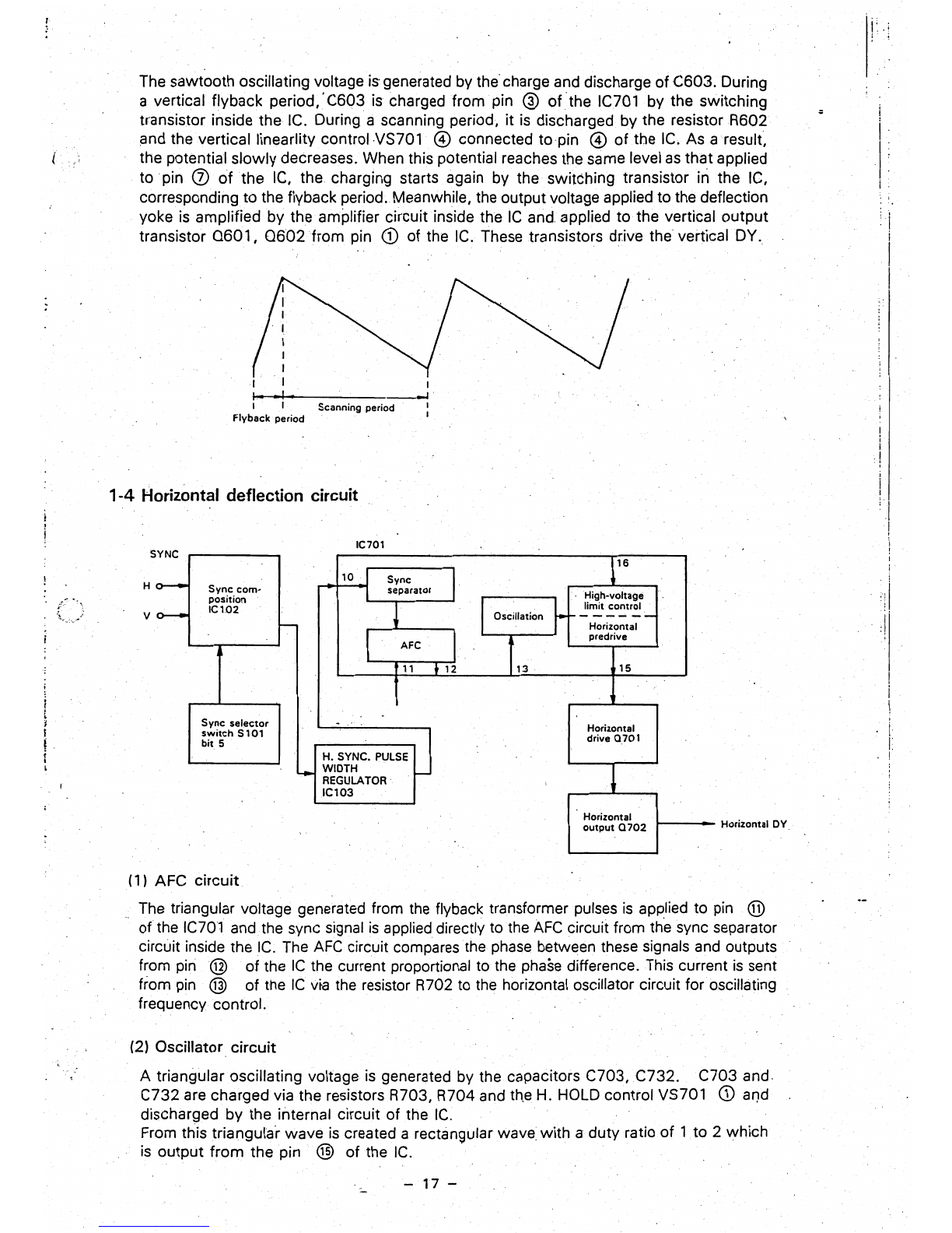
The sawtooth oscillating voltage isgenerated by
the'
charge
and
discharge of C603. During
a vertical flyback period,'C603
is
charged from pin @ of
the
IC701 by the switching i
transistor inside the
IC.
During a scanning period, it
is
discharged by the resistor R602 ~
and the verticallinearlitycontrol
VS701
@ connected to·pin @ of the
IG.
As aresult, i
....
the potential slowly decreases. When this potential reaches the same level
as
that applied ,
to pin
Q)
of
the
IC,
the charging starts again by the switching transistor in the
IC,
I
i
corresponding to the flyback period. Meanwhile, the output voltage applied to the deflection
yoke
is
amplified by the amplifier circuit inside the
IC
and.
applied to the vertical output
transistor Q601,
0602
from pin
CD
of the
IC.
These transistors drive the vertical
DY.,
:1
;
I
I
I
I
••
1.
----J
I I Scanning period
Flyback period I
I
:!
I
1-4
Horizontal deflection circuit
IC701
SYNC J
16
10
I Sync
H
0--
Sync
com·
separator
I , High·voltage
position
IC102
limit control
v
0--
IOscillation
~
---~--
f-
Horizontal
;
t
Sync
selector
I
switch
S101
L
bit
5
;
I
L
(1)
AFC circuit,
predrive
AFC
l I
l,3
''
11
• 12 15
. Horizontal
drive 0,701
H.
SYNC.
PULSE
"-
WIDTH
-
REGULATOR I
ICt03
Horizontal Horizontal
DY
output
0702
'.
The
triangular voltage generated from
the
flyback transformer
pulses
is
applied to
pin
®
of the
IC701
and the sync signal
is
applied directly
to
the
AFC
circuit from the sync separator
circuit inside the
IC.
The
AFC
circuit compares the
phase
between
these
signals
and
outputs
from
pin@
of the
IC
the current proportional to
the
phase
difference.
This
current
is
sent
from
pin
® of the
IC
vta
the
resistor R702
to
the
horizontal oscillator circuit for oscillating
frequency control.
(2) Oscillator circuit
A triangular oscillating voltage
is
generated
by
the capacitors
C703,C732.
C703 and.
C732
are
charged via the resistors R703, R704 and
th,e
H.
HOLD
control VS701
<D
ar)d
discharged by the internal circuit of the
IC.
From this triangula'r wave
is
created a rectangular
wave:
with a duty ratio
of
1,
to 2 which
is
output from the pin @ of the
IC.
-17 -

(''.
~.
. .
•
"(3) Horizontal drive, horizontal ouput circuit
Since
an
approximate 400 mAp-p must flow
in
the base of the horizontal outputtransistor
0702,
the oscillating voltage
is
amlifiedby the drive circuit composed of 0701 and T701.
Consequently, a linearlyincreasing current flows
in
the coil.
VVhen
Q702
is
non-conducting,
the current previously flowing in
0702
comes to
flowinC717,
C718, C719 for resonance
with these capacitors
and
the coil.
Athalf
of
the resonance cycle, the current direction iSJeversed and the current nowflows
through the damper diode (inside 0702)
+'.
By
making
0702
conducting again while the
current flows
in
this diode, a periodic sawtooth current
is
allowed to flow
in
thehorizontal
coil.
,
..
,L" i r
;/
't
a
702
conduction Resonance Damper diode +11 "
630/640
E,
A,
8,
J,S
period period conduction period
An
approximate 1
kVp-p
pulse voltage generated
by
resonance of the capacitors
and
coil
is
boosted by T703
(FBT)
and
supplied to
each
CRT
electrode, the vertical output circuit, video
circuit, etc.
(4) High-voltage
limit
control circuit
If a high voltageapplit;d to
CRT
from T703
(FBT)
rises abnormallyfor some reason
and
exceeds approximately 28 kV, the high-voltage detector voltage output from pin 0 of
T703
(FBT)
is
applied to pin @
of
IC701, which stops the output
of
the horizontal
predrive inside the IC701.
9
r.
'"
. !.
"
.
;
..
-
18
-
This manual suits for next models
3
Table of contents
Other Taxan Monitor manuals


