Taxan KG-BRPL1 Assembly instructions

KG-BRPL1
Ceiling mounting bracket
4-Bracket Fixing Bolts(M4X8) 1-Cable holder
4-Bracket Fixing Nuts
4-Bracket Legs
添付品/ Accessories
4-Anchor bolts
Interface 1-Interface Fixing Bolt (1/4-20 UNC)
4-Interface Fixing Bolts (M4X10)
Installation and setup guide
幅
Width
高さ
Height
奥行
Depth
重量
Weight
仕様/
Specifications
製品名
Name of Product
天井取付用ブラケット
Ceiling bracket 115mm 86.6mm 115mm 0.7kg
Installation and Setup Guide
天井取付用ブラケット
取付説明書
このたびは「弊社プロジェクタ天井取付用ブラケット」をお買い上げい
ただき、誠にありがとうございました。製品の機能を十分にご活用いた
だくために、ご使用前にこの「取付説明書」をよくお読みください。
なお、お読みになった後も必ず保管してください。
プロジェクタの取り付けには特別な技術が必要です。お客様による
工事は、一切行わないでください。
設置工事は据付部の強度計算等の専門知識が必要ですので、工事は
専門業者にご依頼ください。
Thank you for your purchase of the projector ceiling mounting
bracket.
Please read this installation and setup guide carefully to ensure
proper use.
Special skills are required for the installation of the
projector.
This work should never be performed by the customer.
ブラケット取付用脚(4 個) ブラケット固定ナット(4 本) ブラケット固定ボルト(M4x8)(4 本) ケーブルホルダー(1 個) アンカーボルト(4 本)
取付説明書(1 冊)
接続板 接続板固定ボルト
(1/4-20 ユニファイ並目)
(1 本) 接続板固定ボルト(M4x10)(4 本)
- 11 -
- 11 -
2
必ず守ってください
ご使用の前に
絵表示について
この「取付説明書」では、製品を安全に正しくお使いいただき、
あなたや他の人々への危害や財産への損害を未然に防止するた
めに、いろいろな絵表示をしています。その表示と意味は次の
ようになっています。内容をよく理解してから本文をお読みく
ださい。
警告
注意
この表示を無視して、誤った取り扱いをす
ると、人が死亡や大けがをするなど人身事
故の原因となります。
この表示を無視して、誤った取り扱いをす
ると、人がけがをしたり周囲の家財に損害
をあたえたりすることがあります。
記号は注意(警告を含む)をうながす内容があること
を告げるものです。
図の中に具体的な注意内容(左図の場合は感電注意)が描
かれています。
記号はしてはいけないことを表しています。
図の中に具体的な禁止内容(左図の場合は分解禁止)が描
かれています。
●記号はしなければならないことを表しています。
図の中に具体的な指示内容が描かれています。
絵表示の例
警告
●
プロジェクタを設置および角度調整する際は、必ず本書に基
づいて行ってください。
誤った設置および角度調整はプロジェクタが落下してけがの
原因となります。
●
落下防止のため取付け場所の強度および固定方法は、プロ
ジェクタおよび天井取付用ブラケットなどの総合荷重に長期
間十分耐え、また地震にも十分耐える施工を行ってください。
誤った取付けを行った場合、プロジェクタが落下してけがの
原因となります。
以下の事項を必ずお守りください。
・天井固定部品のボルトは M8 を使用してください。
・プロジェクタの電源はコンセントを使用してください。直
接電灯線に接続することは危険ですので行わないでくださ
い。また、電源プラグを抜き差しできるように手のとどく
コンセントをご使用ください。
・天井が木造の場合の取付け
荷重は必ず梁に持たせるようにし、梁の強度が不足する場
合は、補強してください。天井の幅木や受け木には取付け
ないでください。また、鉄骨梁の吊り天井の場合も荷重を
梁に持たせ、天井吊り金具などには取付けないでください。
・天井がコンクリートの場合の取付け
プロジェクタの荷重に十分耐える市販品のアンカーボルト
(M8)をお求めください。
●
安全確保のため、ボルトおよびねじ類は確実に締めつけて
ください。また、ブラケットなどの金属類は必ず添付品を
ご使用ください。
プロジェクタが落下してけがの原因となります。
●
固定したブラケットのミゾに取付け台を合わせるとき、確実
に入っていることを確かめてください。
プロジェクタが落下してけがの原因となります。
●
部品を改造しないでください。
プロジェクタが落下してけがの原因となります。
●
こわれた部品を使用しないでください。プロジェクタが落
下してけがの原因となります。
万一、部品が壊れた場合は販売店にご相談ください。
●
電源が入っているときはレンズをのぞかないでください。
レンズからは強い光が出ていますので視力障害の原因とな
ります。
●
プロジェクタの通風孔をふさがないでください。通風孔
をふさぐと内部に熱がこもり、火災の原因となることが
ありますので、次のような使いかたはしないでください。
たとえば、プロジェクタを壁などの狭い風通しの悪いと
ころに設置する・カバーなどでおおい隠すなど。
●
プロジェクタを冷暖房の吐き出し口や振動の多い場所には
設置しないでください。
火災・感電の原因となることがあります。
●
湿気やほこり、油煙や湯気の当たるようなところ(調理台
や加湿器のそばなど)に設置しないでください。
火災の原因となることがあります。
●
プロジェクタを設置するときは周囲から十分な間隔をあけ
てください。
十分な間隔をあけないと内部に熱がこもり火災の原因とな
ることがあります。
注意
お願い
ホコリや湿気、油煙やタバコの煙の多い部屋は避けてください
レンズ・ミラーなど光学部品に汚れが付着して、画像が悪くなる原因
となります。
直射日光や照明の光がスクリーンに当たる場所は避けてください
スクリーンに周辺の光が直接当たると画面が白っぽくなり見にくい
画面となります。
高温または低温になる場所には設置しないでください(使用温度:5℃〜 35℃)
故障の原因となります。

• When installing the projector, be sure to do so as explained
in this manual. The projector may fall and cause injury if it
is installed improperly.
• To prevent the projector from falling, install it in a place and
fasten it in a way with sufcient strength to support the com-
bined weight of the projector and the ceiling mount unit for
an extended period of time as well as to withstand earth-
quakes. Insufcient strength or fastening may result in the
projector falling and causing injury.
• To ensure safety, be sure to tighten the bolts and screws
securely. Also be sure to use the included units and other
metal ttings. Failure to do so may result in the projector
falling and causing injury.
• When sliding the opening of the mounting adapter over the
pin of the ceiling attachment unit, check that the pin of the
ceiling attachment unit is fully seated in the opening. If not,
the projector may fall and cause injury.
• Do not modify any parts. Doing so may result in the Data
projector falling and causing injury.
• Do not use broken parts. Doing so may result in the pro-
jector falling and causing injury. If a part should be bro-
ken, consult your dealer.
• Do not look into the lens when the projector is turned on.
Doing so could damage your eyesight.
• Make adjustments as described in this manual.
Incorrect adjustments may result in the projector falling
and causing injury.
CAUTION
• Do not obstruct the projector's ventilation holes. Doing
so will prevent the dissipation of heat and may result in
res. In particular, do not use the projector in the follow-
ing ways:
Do not install the projector in a wall or in a tight place
where ventilation is poor, place a cover it, etc.
• Do not install the projector in front of the outlets of an
airconditioner or heater or in a place where vibrations
are strong.
Doing so may result in res.
• Do not install the projector in humid or dusty places
or exposed to smoke or steam (such as near cooking
equipment or humidiers). Doing so may result in res.
• When installing the projector, leave sufcient space be-
tween it and surrounding objects. Failure to leave suf-
cient space will prevent the dissipation of heat and may
result in res.
• DO NOT REMOVE ANY SCREWS except specified in
the manual.
• When removing the screws on left and right on the mount-
ing adapter, be sure to support the projector while doing so.
Failing to do so may result in the projector swinging back
abruptly and causing injury.
• for PLUGGABLE EQUIPMENT, the socket-outlet shall be
installed near the equipment and shall be easily acces-
sible.
Installation Precautions
• Special techniques are required for the installation work
of the projector and installation work should only be un-
dertaken by qualied and licensed installers.
• KAGA COMPONENTS will not accept any responsibility
related to any accidents or incidents due to insufcient or
inferior mounting techniques.
Installation Location
Avoid places of high temperature or low temperature. (Am-
bient operating temperature: 5˚C to 5˚C)
Avoid places exposed to direct sunlight and the vicinity of
ventilation holes of room air conditioning and heating.
Avoid rooms with a lot of dust, humidity, greasy smoke, or
tobacco smoke.
Dirt will adhere to optical parts such as lenses and mirrors
and this will cause a deterioration of image quality.
Avoid places in which the screen is exposed to direct sunlight
or illumination light.
When surrounding light directly hits the screen, the image ap-
pears washed out and is difcult to view.
WARNING
Heed the Following

4
Guide to Screen Size and Projector Mounting Position
• Use this information as a guide to nd out about what the screen size will be for the projected video when placing the projector.
• The projection distance over which focusing is adjustable is 406 mm to 2228 mm from the projector lenssurface. The projector
should be placed within this range.
• It will be necessary to change the projection method when the projector is installed suspended from the ceiling. See “VerticalFlip /
Horizontal Flip“. (See the User’s Manual of a projector.)
画面サイズとプロジェクタ取付け位置の目安
●プロジェクタ本体を設置する際に、投映される映像がどのくらいの画面サイズになるかを知りたいときの目安にしてください。
●
フォーカス ( 焦点 ) の合う投映距離は本体レンズ面から 406mm 〜 2228mm です。この範囲内に設置してください。
●プロジェクタを天吊り設置する場合は投映方法を変更する必要があります。「上下反転/左右反転」をご参照ください。
(プロジェクタの取扱説明書参照)
スクリーン
投映距離 (D)
投映距離 (D)
スクリーン
スクリーン高さ (X)
スクリーン幅 (Y)
Screen Width (Y) Screen
Screen Height (X)
Screen
Projection Distance (D)
Projection Distance (D)
設計値のため、±5%の誤差があります。
この表はレンズ先端およびレンズ中心を基準とし、
また、本体が水平の状態(アジャスタを縮めた状態)
で表しています。
・
・
スクリーン高さ(X)
スクリーン幅(Y)
スクリーン呼び名(インチ)
スクリーンサイズ( 対 角 )
画面サイズと投映距離
Screen Width (Y)
Screen Height (X)
Screen size (diagonal)
Screen size Desognation (inchs)
Screen Size and Projection Distance
•
•
There is a tolerance of ±5% due to design values.
This table uses the lens apex and lens center as
references and requires that the projector be in a
horizontal condition (with front and rear adjusters
fully withdrawn).
スクリーン呼び名(インチ)
Screen Size Desognation (inchs)
15″
20″
25″
30″
35″
40″
45″
50″
55″
60″
65″
70″
75″
80″
スクリーンサイズ(対角)
Screen Size (diagonal)
381
508
635
762
889
1016
1143
1270
1397
1524
1651
1778
1905
2032
スクリーン幅(Y)
Screen Width (Y)
305
406
508
610
711
813
914
1016
1118
1219
1321
1422
1524
1626
スクリーン高さ(X)
Screen Height (X)
229
305
381
457
533
610
686
762
838
914
991
1067
1143
1219
投映距離(D)
Projection Distance (D)
406
546
686
827
967
1107
1247
1386
1528
1668
1807
1948
2088
2228
単位/ Unit:mm
4:3(縦横比/ Aspect ratio)
5
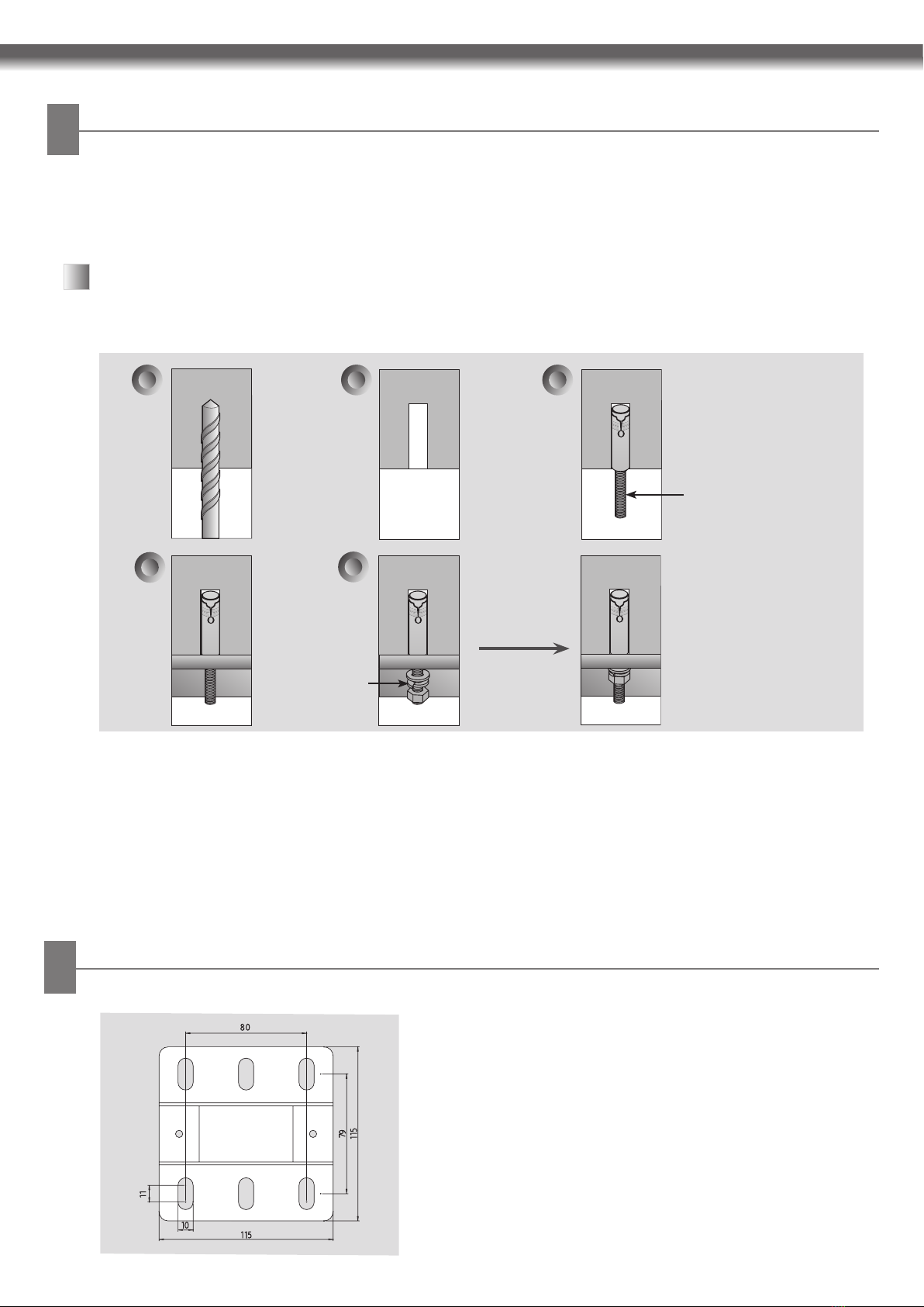
- Check the ceiling material and thickness. Anchor bolts can only be used if the ceiling material is concrete. Do not use anchor
bolts for plasterboard or medium density fiberboard (MDF).
ab
e
washer and nut
c
Ancher bolt for celling
bracket installation
- The type of anchor bolt to use may differ depending on the installation environment. Purchase appropriate anchor bolts
suitable for your installation environment.
- Refer to the dimensions when tightening anchor bolts (Top-side
dimensions of the ceiling bracket).
a. Use a 12mm drill bit to make holes of 42~44mm in depth
for the anchor bolts.
b. Clean each drilled hole.
c. Insert an anchor bolt into each hole. Tighten each bolt with
a torque in excess of 150kgf•cm.
d. Mount the celling bracket on the celling.
e. Assemble the washers and nuts in order.
d
Installing Anchor bolts
Reference Dimensions When Tightening Anchor Bolts
アンカーボルトの取付け穴位置参考寸法
- アンカーボルトは取付け環境によりタイプが異なります。お客さまのご使用環境に合った正しいアンカーボルトをお求
めください。
アンカーボルトの取付け
-
プロジェクタを取付ける天井の材質と厚さを確認してください。アンカーボルトの使用はコンクリート天井の場合に
限られます。天井の材質が石膏ボードまたは中質繊維板(MDF)の場合は、アンカーボルトは使用しないでください。
ブラケット取付け用
アンカーボルト
ワッシャとナット
a. 12mm のドリルビットを使用してアンカーボルト用の
深さ 42 ~ 44mm の穴を開けます。
b. ドリル屑などを拭って穴をきれいにします。
c. 各穴にアンカーボルトを挿入し、150kgf・cm 以上の
トルクで締め付けます。
d. 天井にブラケットを取付けます。
e. ワッシャとナットをセットにして組合わせておきます。
- アンカーボルト締付け時の寸法は左図(天井取付用ブラケット
の上部側面寸法図)を参照してください。
6
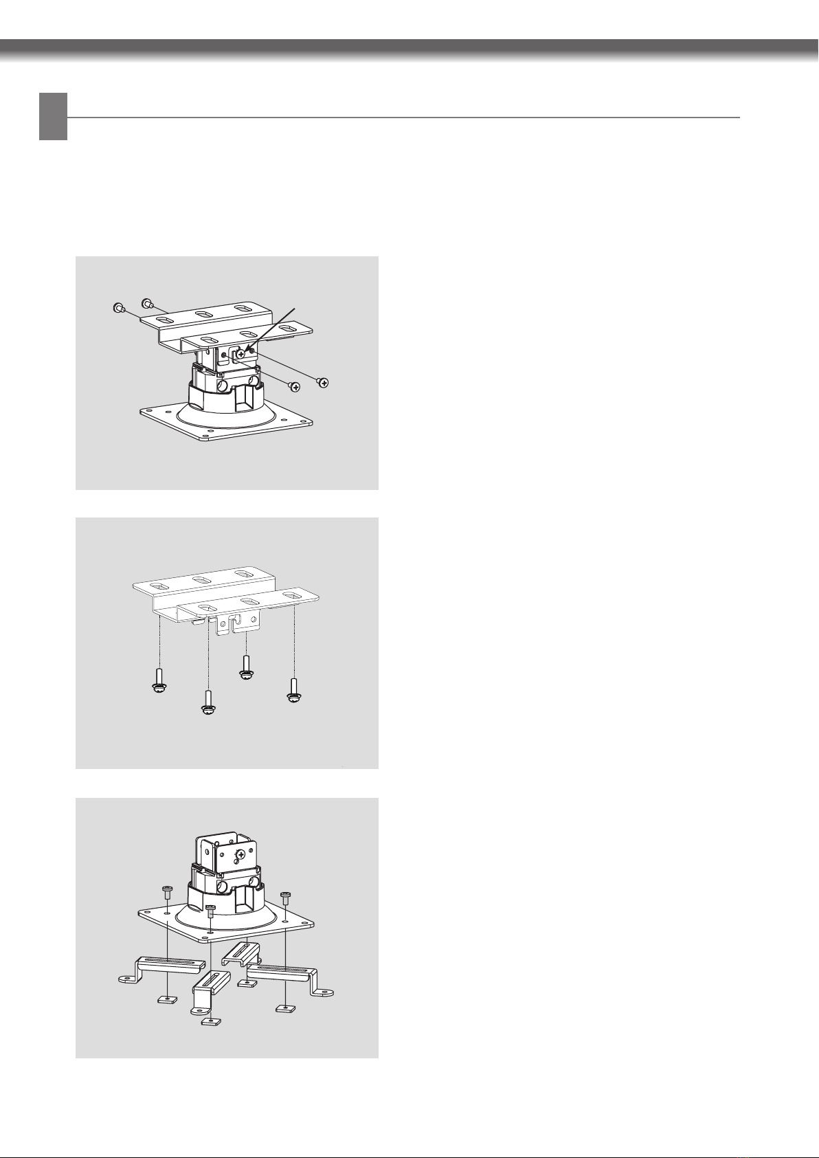
E Disassemble the bolts on the left and right as shown in the
image.
E Leave the fixing bolts on the left and right temporarily
assembled, and disconnect the ceiling bracket.
Fixing bolt
E Use the bolts (M4X8)and nuts provided to temporarily
assemble the mount and the legs.
E Fix the bracket to the ceiling.
For this, purchase appropriate bolts depending on the ceiling
material.
- The images below are provided to help you understand how to install the ceiling bracket;however the actual product
may differ slightly.
Installing Ceiling Mounting Bracket
天井取付用ブラケットの取付け
- 以下の図はブラケットの取付け手順を分かり易く示した説明図です。実際の製品とは幾分異なる場合があります。
E 図に従って左右 4 本のボルトを取外します。
E 左右の固定ボルトを仮締めの状態でブラケットを外します。
固定ボルト
E ブラケットを天井に固定します。
天井の材質により使用するボルトの種類が異なります。
適切なボルトをお求めください。
E 付属の M4x8 固定ボルトとナットを用いて取付け台と
脚を仮留めします。
7
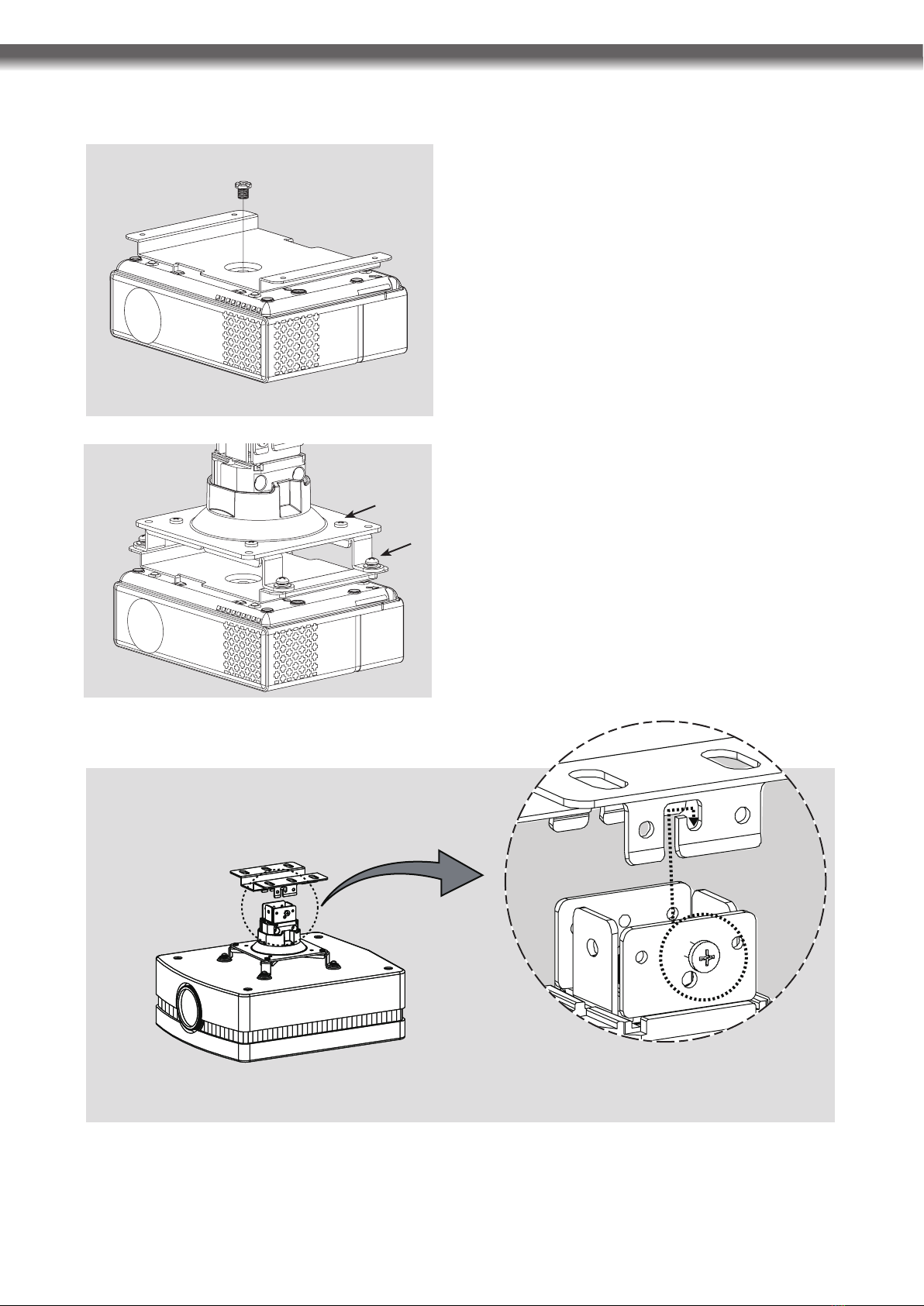
E 組立てが出来ましたら全体を拡大図が示す矢印の方向に持上げ、ブラケットに固定ボルトを嵌め込みます。
E Place the interface on the projector and secure it with the
bolt (1/4 20-UNC).
E Then secure the mount with 4 bolts (M4X10).
E Lift the mount slightly and move it left or right to adjust the
center of balance for the projector.
E Fix the bolts (1) and (2) at the four corners.
E プロジェクタの上に接続板を置き、付属の 1/4-20 ユニ
ファイ並目ボルトでしっかり取付けます。
E 付属の M4x10 ボルト 4 本で接続板に取付け台を取付
けます。
E 取付け台を少し上に浮かして左右に動かし、プロジェク
タのバランスの中心を調整します。
E 四隅のボルト(1)と(2)を締付け固定します。
E Offer the assembly up as shown in the dotted circle in the direction of the arrow and fix the mount to the ceiling bracket.
(1)
(2)
※取付けイメージです、プロジェクタ本体のイラストは KG-PL105S ではありません。
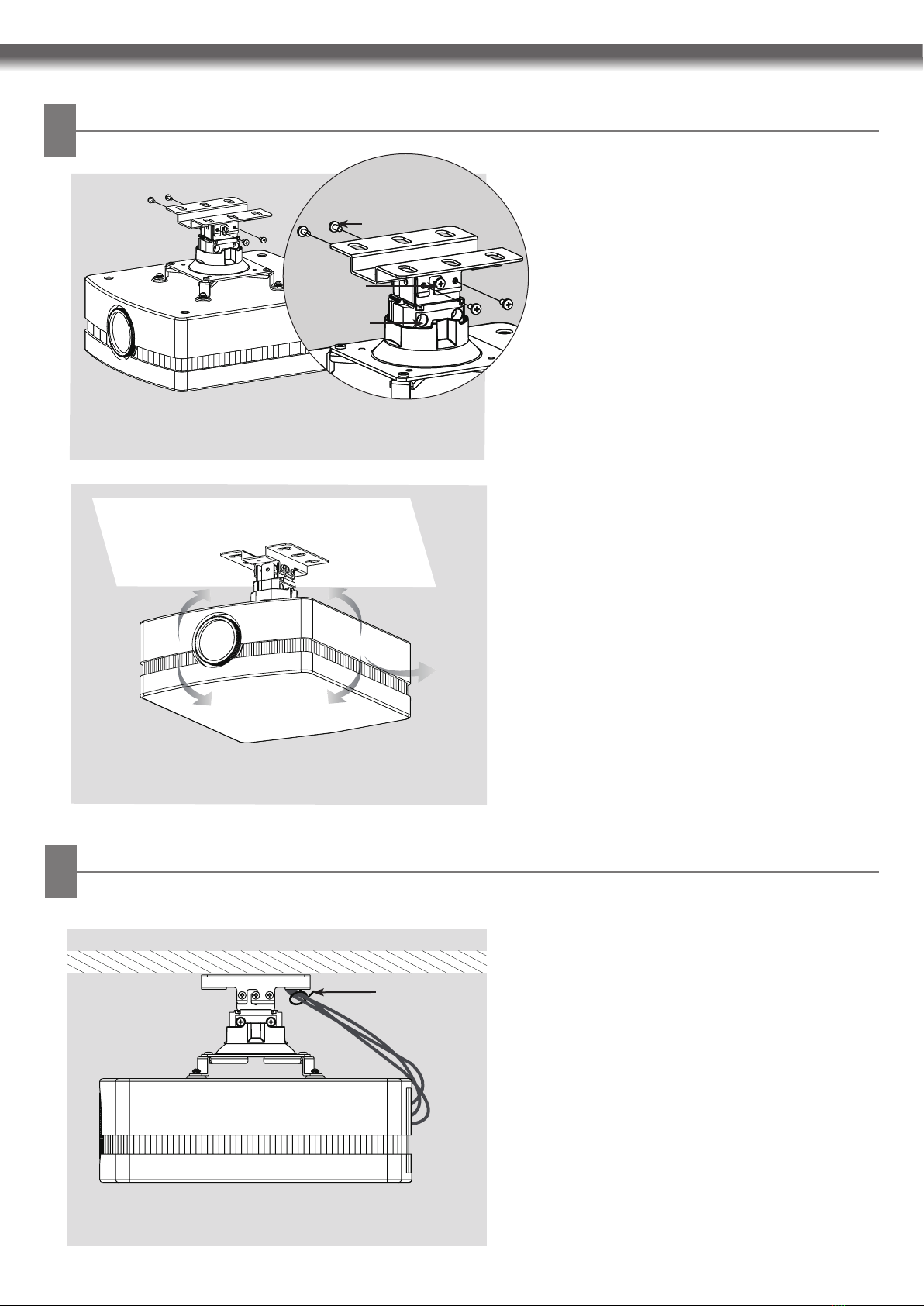
E Adjust the angle based on your environment as
shown in the image. The product is adjustable by
up to 10° vertically and 60 horizontally. When
rotating the product horizontally, make sure it does
not interfere with the cables.
±10°±10°
60°
E Use the cable holder to organize the cables as
shown in the image.
Cable holder
E Use 4 (1)bolts and 2 (2)bolts on the left and right to
fix the bracket and the mount.
E For a product weighing more than kg, tighten the
2 ()bolts to fix it more firmly after adjusting the
angle (When readjusting the angle, loosen the 2
()bolts by about 6mm).
(1)
(2)
()
Adjusting Angle
角度調整
Organizing Cables
ケーブルの整理
E 左右のボルト(1)4 本とボルト(2)2 本を用
いてブラケットと取付け台を固定します。
E 製品の重量が 3kg を超える場合は、角度調節後
更にボルト(3)2 本で確実に固定してください。
(角度の再調整が必要な場合は、このボルト(3)
2 本を 6mm ほど緩めてください。)
E 実際の取付け状況にしたがって角度調整を行っ
てください(左図参照)。垂直方向は± 10 度の
範囲まで、また、水平方向は 360 度の角度調整
が可能です。水平方向の角度調整のために製品を
回転する際にはケーブルを引っ掛けないように注
意してください。
E ケーブルホルダーを用いてケーブルをまとめます
(図参照)。
ケーブルホルダー
8
※取付けイメージです、プロジェクタ本体のイラストは KG-PL105S
ではありません。
※取付けイメージです、プロジェクタ本体のイラストは KG-PL105S
ではありません。
※取付けイメージです、プロジェクタ本体のイラストは KG-PL105S
ではありません。
Table of contents


