THOR 28060T User manual

Pull down the locking block on the wall plate using the locking
cord and after it clicks into position gently release.
If you need to dismount the TV pull
down the locking cord
and gently release.
You can then lift
the TV off the
wall plate. W-A
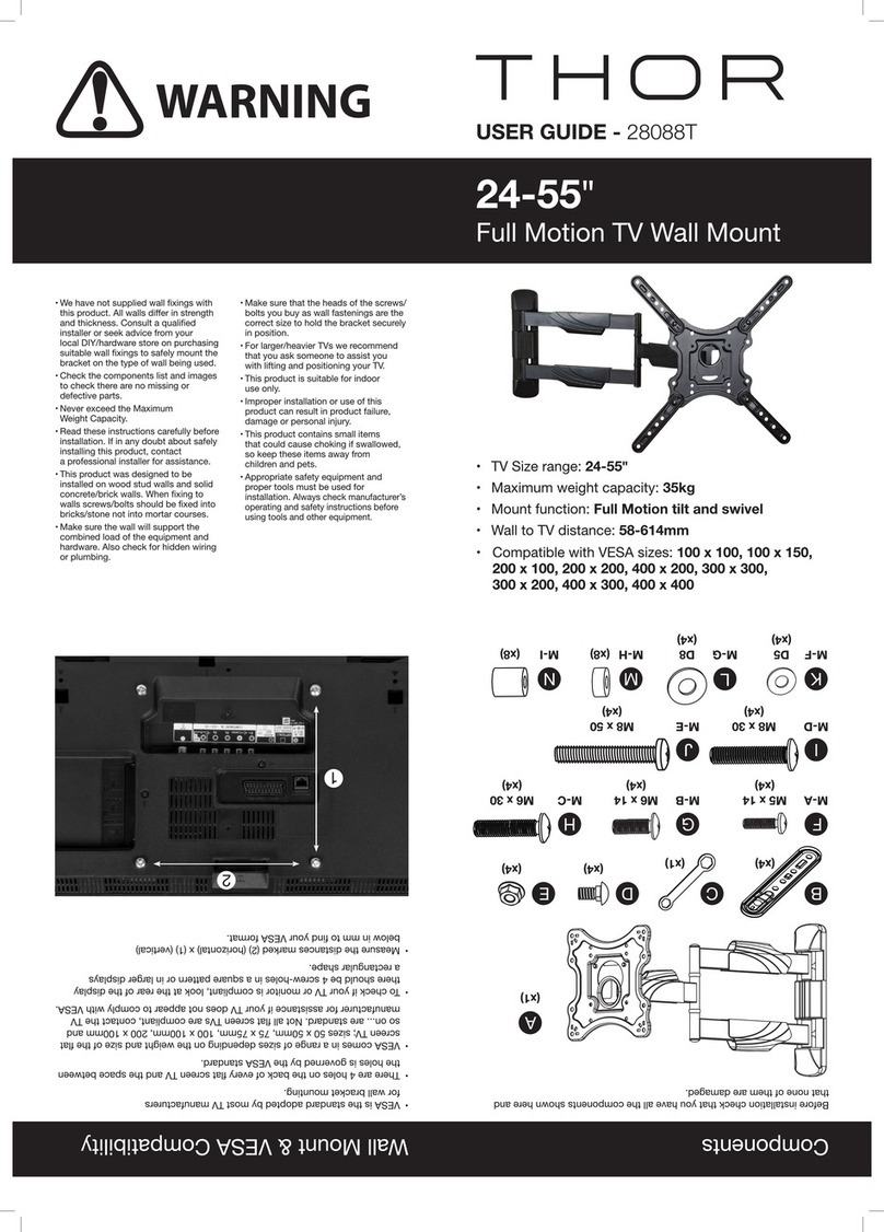
USER GUIDE - 28060T
42-70"
Multiwall TV Wall Mount
• TV Size range: 42-70"
• Maximum weight capacity: 50kg
• Mount function: Tilts 0°/-5°
• Wall to TV distance: 31mm
• Compatible with VESA sizes:
200 x 200, 300 x 200, 300 x 300, 400 x 200,
400 x 300, 400 x 400, 600 x 400
Components
WARNING
A
2
1
Wall Mount & VESA Compatibility
• Please read these instructions carefully
before installation. If in any doubt about
safely installing this product, contact a
professional installer for assistance.
• To ensure safe installation make sure that the
surface you are mounting your bracket on is
in a good state of repair and that
the wall will
support the combined load of the equipment
and hardware. Also check for hidden wiring or
plumbing.
• Check the components list and images to
check there are no missing or defective parts.
• Never exceed the Maximum Weight Capacity.
• To prevent overheating it is advisable not to
mount your TV directly over a replace or
radiator.
• This product was designed to be installed
on plasterboard, wood stud walls and solid
concrete/brick walls. When xing to walls
screws/bolts should be xed into bricks/
stone not into mortar courses.
• For larger/heavier TVs we recommend that
you ask someone to assist you with lifting
and positioning your TV.
• This product is suitable for indoor use only.
• Improper installation or use of this product
can result in product failure, damage or
personal injury.
• This product contains small items that could
cause choking if swallowed, so keep these
items away from children and pets.
• Appropriate safety equipment and proper
tools must be used for installation.
Always
check manufacturer’s operating and safety
instructions before using tools, ladders and
other equipment
.
M-C M-D
M8x50(x4)
M6x30(x4)
x1
M-B
M6x14(x4)
x1
x1 x1
M5x14(x4)
M-A
M8x30(x4)
D5x(x4) D8x(x4) x8 x8
M-E M-F M-G M-H M-I
© Philex Electronic Ltd. 2019. V1
Technical Support:
www.philex.com/support
• VESA is the standard adopted by most TV
manufacturers for wall bracket mounting.
• There are 4 holes on the back of every at
screen TV and the space between the holes
is governed by the VESA standard.
• VESA comes in a range of sizes depending on
the weight and size of the at screen TV;
sizes 50 x 50mm, 75 x 75mm, 100 x 100mm,
200 x 100mm and so on... are standard.
Not all at screen TVs are compliant, contact
theTV manufacturer for assistance if your
TV does not appear to comply with VESA.
• To check if your TV or monitor is compliant,
look at the rear of the display there should
be 4 screw-holes in a square pattern or in
larger displays a rectangular shape. • Measure the distances marked (2) (horizontal)
x (1) (vertical) below in mm to nd your
VESA format.
7. Mounting the TV on the Wall Plate
With two people, lift the TV
with the TV plate and standoffs
attached and hook the
TV plate Bover the lip
on the wall plate A, as shown
in Fig. 10/11/12.
Centre the TV on
the wall plate and
lock in place.
x4 x4 x4 x20
Before installation check that you have all the components shown here and
that none of them are damaged.
B
C D
W-D
W-CW-B
Components
Fig.10
Fig.11
Fig.12
Fig.13
Pull down and
release the
locking chord
to lock and
unlock
8. Locking and Unlocking the TV plate

The wall plate Ais attached to the wall using 2x W-A screws and 2x W-C
washers supplied. Use a stud detector to nd and mark the position of the studs
in the chosen location. Offer up the wall plate using a spirit level to get it level and
mark the screw positions as shown Fig.3. Use a 4.5mm drill bit to drill 2x 55mm
deep holes as close as possible to the centre of the uprights. Attach the wall plate
using the screws and washers (see Fig.4. for studs 400mm apart and Fig.5. for
studs 600mm apart).
2. Attaching to Stud Walls
Tools required
3. Attaching to Concrete/Brick Walls
Tools required
Fig.6
Select the correct size bolts to t the VESA holes for your TV M-A /M-B /M-C /M-D /
M-E .Attach the TV plate Bto the back of the TV by lining up the top VESA holes
and using bolts M-A /M-B /M-C /M-D /M-E and the washers M-F /M-G and spacers M-H
/M-I (if required) to x the TV securely to the adaptor brackets. Use the same
combination of bolts, washers and spacers to attach the two standoffs Cto the
lower VESA holes.
4. Attaching the TV Plate and Standoffs to the TV
to give 0° Screen Tilt
Fig.8
The wall plate Ais attached to the wall using 4x W-A screws, 4x W-B wall plugs
and 4x W-C washers supplied. Offer up the wall plate using a spirit level to get it
level and mark the screw positions as shown Fig.6. Use a 10mm drill bit to drill
4x 60mm deep holes. Insert the wall plugs W-B into the holes and attach the wall
plate using the screws W-A screws and washers W-C (see Fig.7).
Fig.7
1. Attaching to plasterboard
Tools required
Place the wall plate A in the position chosen and gently hammer in the rst nail W-D
on the extreme left or right end of the wall plate at the angle and to the depth shown
in Fig.2. Then check the plate is level (using a spirit level) before hammering in a nail at
the other end, next hammer in the remaining 18 nails.
Please Note: Installation is best carried out by two people, one to hold the wall plate in
position and the other to hammer in the nails.
Be careful not to knock the nails all the way through the plasterboard.
Make sure the plasterboard is in good condition and has not been exposed to damp
at anytime.
Installation
A
W-D
Fig.1
Fig.2
Fig.3
Fig.4
Fig.5
400mm
Select the correct size bolts to t the VESA holes for your TV M-A /M-B /M-C /M-D /
M-E .Attach the TV plate Bto the back of the TV by lining up the top VESA holes
and using the bolts M-A /M-B /M-C /M-D /M-E , washers M-F /M-G and spacers M-H /M-I
(if required) to x the TV securely to the adaptor brackets. Use the same combi-
nation of bolts, washers and spacers to attach the two standoffs Dto the lower
VESA holes. If you want to adjust the -5° tilt angle slightly you can in some in-
stances add or remove spacers on the standoff.
6. Attaching the TV Plate and Standoffs to the TV
to give -5° Screen Tilt
Fig.9
600mm
Other THOR TV Mount manuals
Popular TV Mount manuals by other brands

Vivo
Vivo MOUNT-POLE01W instruction manual
Pioneer
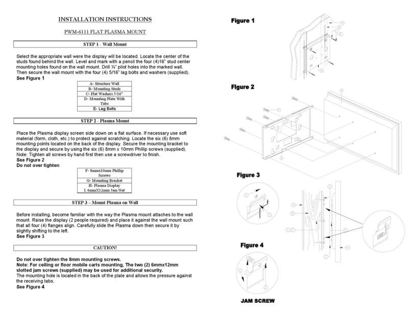
Pioneer PWM-6111 installation instructions

Sony
Sony KDS-R50XBR1 - 50" Grand Wega™ Sxrd™ Rear Projection... instructions
Intelbras
Intelbras XSA 1000 user manual
Ridem
Ridem RDM S13 instruction manual
Metra Electronics
Metra Electronics 99-5830B installation instructions
