Taylex ABS1500 User manual

INSTALLATION MANUAL
CONCRETE ADVANCED BLOWER SYSTEM 1500 (ABS1500)

TABLE OF CONTENTS
1. INTRODUCTION .........................................................................................................................2
2. SAFETY INSTRUCTIONS ............................................................................................................2
3. STANDARDS & LICENCING .......................................................................................................3
4. PRE SITE
INSPECTION
................................................................................................................3
5. MARK OUT ..................................................................................................................................3
6. DELIVERY AND PLACEMENT ....................................................................................................4
7. INSTALLATION ...........................................................................................................................6
8. ELECTRICAL CONNECTION ......................................................................................................7
9. COMMISSIONING........................................................................................................................7
10. EXCAVATION & LIFTING INSTRUCTIONS.................................................................................8
a. ABS1500 Standard Excavation Instructions.........................................................................8
b. ABS1500 Standard Lifting Instructions ................................................................................9
c. ABS1500 Tall 300 Excavation Instructions…....................................................................10
d. ABS1500 Tall 300 Lifting Instructions…............................................................................ 11
e. ABS1500 Tall 400 Excavation Instructions… ....................................................................12
f. ABS1500 Tall 400 Lifting Instructions…............................................................................13
g. ABS1500 Tall 600 Excavation Instructions… ....................................................................14
h. ABS1500 Tall 600 Lifting Instructions…............................................................................ 15
11. ELECTRICAL CONNECTION DIAGRAM.................................................................................. 16
Note: Do not act solely on the basis of the material contained in this document. Items herein are
general comments only and do not convey advice per say. We therefore recommend that formal
advice be sought before acting in any of these areas.
1 of 16
Page

Page 2 of 16
1. INTRODUCTION
The Taylex ABS1500 Sewage Treatment System isdesigned tobe installed both in-ground and
above ground,collecting all wastewater from a domestic residence. This manual has been put
together to explain the installation process of the ABS1500 system as a guide only. Some sites may
differ in access and slope which need to be taken into account when delivering and installing the
system.
2. SAFETY INSTRUCTIONS
Follow all safety instruction provided by the onsite builder and ensure
you have all the relevant licences to perform this work.
Ensure the correct measurements are in place to prevent the
general public from entering the site during the installation of the
ABS1500.Excavated holes should be fenced if the ABS1500 is not
immediately installed.
SLIPPERY WHEN WET!
During cleaning, maintenance & repair work, the surrounding area may
become extremely slippery due to spilt water. Caution is to be taken
when walking/standing near the ABS1500 when these activities are
being conducted.
Use safe lifting techniques when installing/relocating the ABS1500.
Ensure that all lifting equipment is in a safe working order and the area is
clear of obstructions. Ensure all lifting equipment used has asuitable
capacity and current testing/compliance.
The waste water contained in the ABS1500 may contain harmful
bacteria. Persons coming in contact with wastewater must immediately
wash and disinfect all exposed areas. Contact your personal physician for
all health concerns.
WARNING - To reduce the risk of electrical shock, all works requiring
access to the blower box MUST be carried out by a licenced electrician or
Taylex Accredited Service Agent (TASA) prior to final commissioning.

Page 3 of 16
3. STANDARDS & LICENCING
All Installations must be completed in accordance with AS/ANZ 3500.1 and AS/ANZ 3500.2
Irrigation Areas/Land Application Areas (LAA) must be installed as per AS1547 and all relevant
State/Local Codes or Guidelines
Ensure the appointed Licenced trades only complete this work – Plumbers/Drainers/Electricial
4. PRE SITE INSPECTION
A pre site inspection should be conducted the day prior to installation. During this inspection the
following details should be checked.
Access requirements for excavation, Crane Truck, Truck or Crane.
•A Crane Truck requires the following:
Access to site – 12m long x 4m wide x 4.5m high
Level Pad at the hole – 12m long x 7m wide
Overhead obstructions
Slope of site
Soil moisture (for heavy equipment access)
Weather conditions
5. MARK OUT
To ensure the ABS1500 is installed in the position nominated by the Home Owner/ Builder, the
location of the ABS1500 should be marked out prior to excavation. The installer at this stage should
have a copy of the approved site plans showing the location of the ABS1500 as well as the required
local authority approval. If not, it is advised to delay the installation until the plans have been received.
Mark out a 3m x 3m square with line marking paint
Place a centre peg in the middle of the square and spray it with white paint or a colour that it
noticeable from a distance
Indicate on the centre peg or by spraying on the ground, which ABS1500 system is being
installed e.g. STD, Tall 300, Tall 400 and Tall 600. This will ensure that the installer installs the
tank to the correct depth (refer to point 7 for depths)
Allow a minimum of 290mm between Tank and the edge of excavation.

Page 4 of 16
Taylex ABS1500 Excavation Mark Out
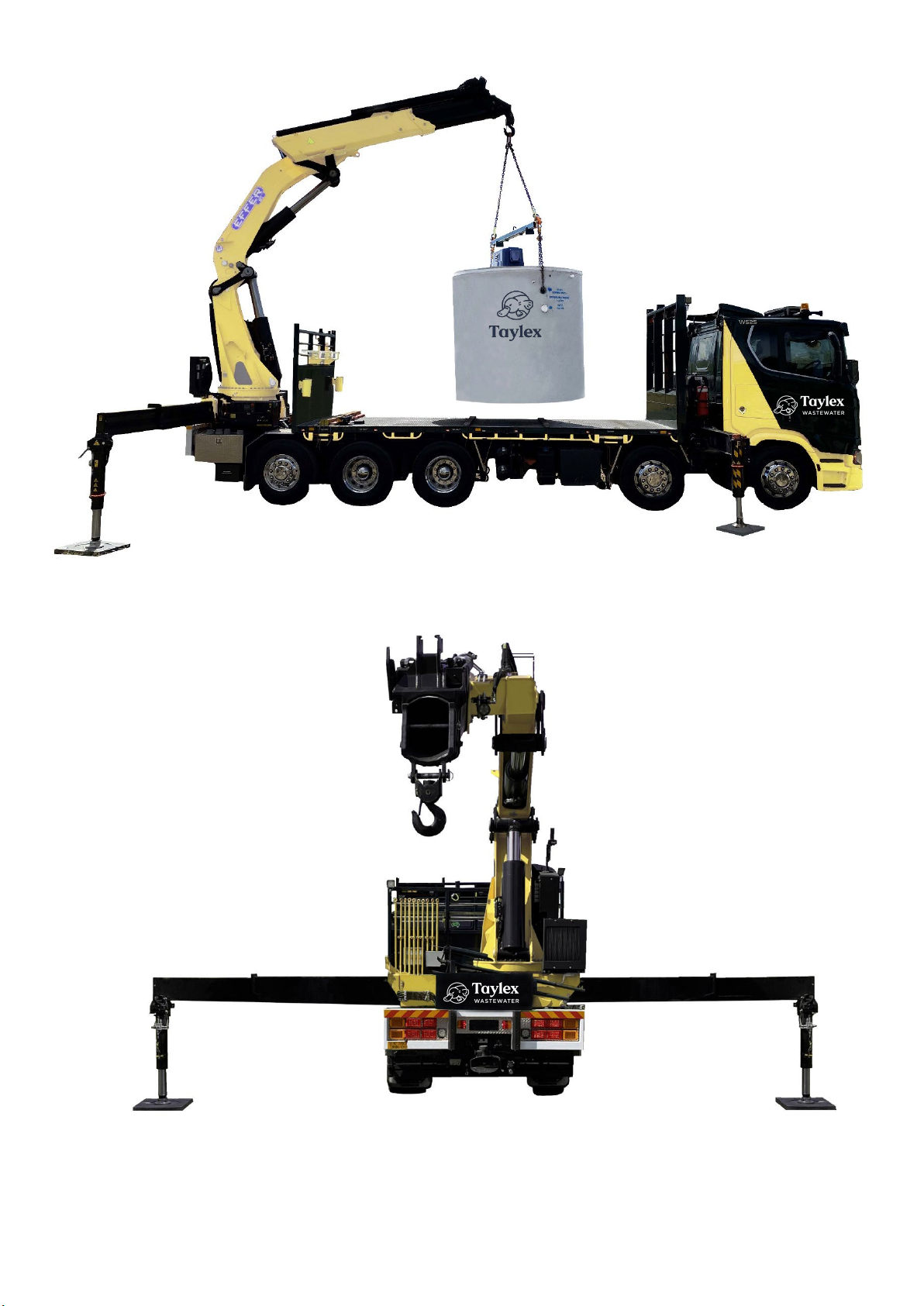
6. DELIVERY AND PLACEMENT
In most areas, tanks will be delivered by a truck equipped with a crane located at the rear
of the vehicle. Such vehicles will back up to the hole, lift and slew the tank into position
behind the vehicle before placing it into the prepared hole. Maximum reach from the rear of
the truck to the centre of ABS1500 will vary depending on the size of the crane.
To enable the ABS1500 to be unloaded, a minimum width of 7m (may vary depending on
crane truck) will be required at the hole. This distance allows for the width of the crane
truck, the width of the tank itself, and clearance for safe and free manoeuvring of the
ABS1500 into the excavated hole.
Page 5 of 16

Page 6 of 16
PLEASE NOTE
Tanks should not be lifted over houses, sheds or other property of value, nor should
they be lifted under low power lines
Tank sites that are cut out of sloping hills will require enough flat area for the truck to
be unloaded
Unloading on awkward and dangerous sites will be at the driver's discretion. Safe
and clear access is the responsibility of the property owner/builder.
7. INSTALLATION
Always ensure the installation location include the future landscaping provision allow for the diversion
of stormwater and surface waters away from the system.
The ABS1500 comes with 4 different heights to accommodate invert levels as deep as 1270mm
below ground level.
Width Height Inlet Height
(from bottom of tank)
Inlet Depth
(from ground level)
Required
Base
(5-7mm Drainage
Gravel/ Sand)
Hole
Width
Hole
Depth
ABS1500 STD*
2425
2300
1530
670
100
3000
2300
ABS1500 Tall 300*
2425
2600
1530
970
100
3000
2600
ABS1500 Tall 400*
2425
2700
1530
1070
100
3000
2700
ABS1500 Tall 600*
2425
2900
1530
1270
100
3000
2900
*Refer to Excavation & Lifting Instructions on Pages 8 - 15
STANDARD TAYLEX ABS1500
2300 mm
1530 mm 670 mm
3000 mm
2425 mm
100 mm 100 mm
350 mm
Lifting
Holes
100mm
Inlet
Lifting
Holes
Top of tank to be a minimum
of 100mm above landscaped ground level

Page 7 of 16
Except for person/s responsible for lifting and positioning of the tank in the excavated hole,
there must not be any person within 20m of the installation site during the lifting and
positioning of the tank.
Excavation Instructions show excavated walls to be perpendicular. However, depending on
the soil conditions, the excavator may need to batter or retain the side walls to ensure they
don’t cave in during installation.
Level the base of the hole using an excavation bucket with a laser level attached.
Ensure that the excavated ground or base material is capable of carrying loads of
approximately 7 tonne (standard ABS1500).
The ABS1500 must be level in both inflow/outflow direction and 90° to the inflow/outflow
direction (<1° deviation).
Backfilling - Use sand or excavated material/spoil with maximum particle size of 50mm.
Backfilling of excavation to be completed in not more than 500mm equally distributed
layers around the tank perimeter. Ensure that sand or excavated material does not fall on
the lid of the ABS1500 as this will fall into the system through the manholes and clog the
system and irrigation pump. Ensure that the backfill material is kept at least 100mm
below the surface of the systems lid.
Evenly fill the system with approximately 5,000L of water through the centre Aeration
Chamber to prevent movement through the ground as the water pressure enters the
system.
Organise drainage contractors to connect to the system. The drainage connection
is a standard 100mm PVC sewer inlet.
Refer to Excavation Instructions on Pages 8-15
8. ELECTRICAL CONNECTION
The electrical contractor must follow the electrical specification supplied with the
ABS1500 system
Ensure all electrical works are only completed by licenced persons.
Ensure all electrical work is completed and compliant with AS/ANZ 3000.
Refer to Electrical Specifications on Page 16
9. COMMISSIONING
Please ensure the following is completed prior to having the system commissioned
Effluent Disposal area is installed
Effluent Disposal Area feed line is connected to ABS1500
Electrical power is connected
Drains connected
IMPORTANT: The Taylex ABS1500 System cannot be commissioned unless power is connected to the
system.
The ABS1500 will then be switched on (commissioned) by an Employee of Taylex Industries, a Taylex
Accredited Distributor (TAD) or a Taylex Accredited Service Technician (TASA).
TAYLEX ABS
EXCAVATION INSTRUCTIONS
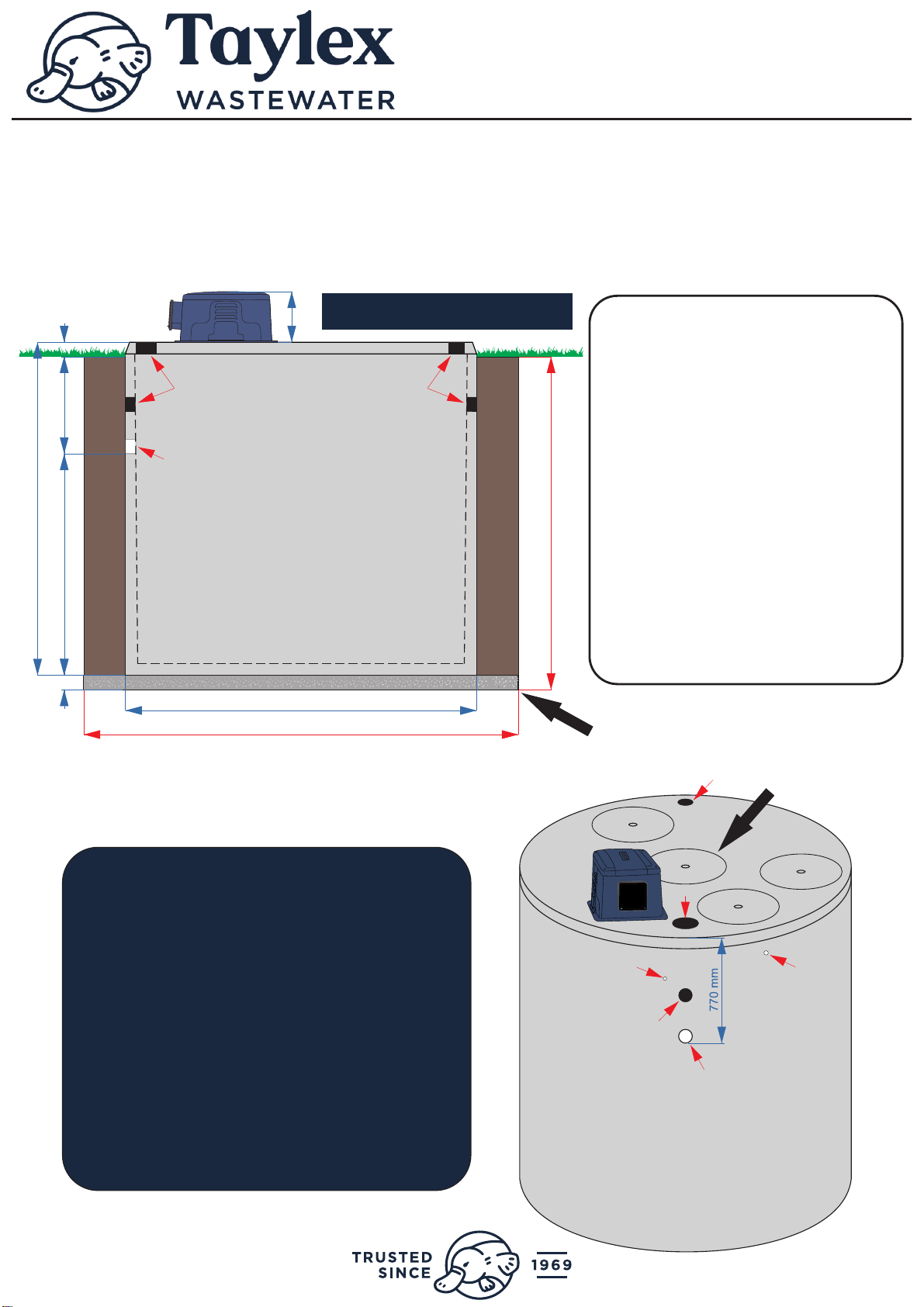
ABS CONCRETE STANDARD
Excavation Instructions
Tank Total Mass = 6.25 Tonne
2300 mm
1530 mm 670 mm
3000 mm
2425 mm
100 mm
2300 mm
100 mm
350 mm
32mm
Irrigation
Outlet
Lifting
Hole
20mm
Electrical
Inlet
100mm
Inlet
Lifting
Hole
Lifting
Holes
100mm
Inlet
Lifting
Holes
100mm of
5mm-7mm
drainage
gravel or sand
Please Note:
5,000lt of water
to be placed in
this chamber to
prevent flotation
Lifting
Hole
1. Dig hole 3000mm square & 2300mm
Deep
2. Ensure drainage has a 1/60 fall to the
inlet of ABS. Risers are available if the
tank needs to be installed deeper in the
ground to maintain fall
3. Cover base of hole with 100mm of
5mm to 7mm drainage gravel or sand
4. Ensure bottom of hole is level
5. Backfill with soil from Excavation in no
more than 500mm equally distributed
layers around the tank. Avoid backfilling
with rocks over 300mm.
6. To prevent flotation, fill the ABS with
5,000lt of water immediately through
hole above the aeration chamber
(see diagram below)
7. Ensure top of gravel/sand is 1530mm
to bottom of inlet
ELECTRICIAN
Connect through conduit on side of ABS.
Run wire (min 2.5mm) through the flexible
conduit provided and up into the switch located
in the blower box.
Active - Neutral - Earth.
TRUCK ACCESS
Unloading of ABS via the back of the truck
NOT SIDE. Ensure BACK of truck has clear
level 6m wide access to the edge of the hole.
REACH OF CRANE/ CRANE TRUCK
To be determined by your crane/ crane truck
operator.
Top of tank to be a minimum
of 100mm above landscaped ground level
Page 8of 16

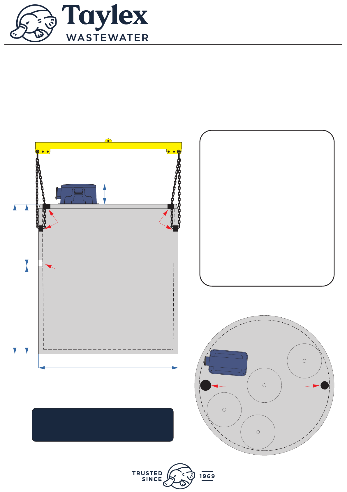
355 mm
ABS CONCRETE STANDARD
Lifting Instructions
Total Mass = 6.25 Tonne
Total Height (with blower box) = 2655mm
Total Width = 2425mm
REACH OF CRANE/ CRANE TRUCK
To be determined by your crane/ crane truck
operator.
Lifting
Holes
Lifting
Holes
Lifting
Hole
USE ONLY CERTIFIED LIFTING BARS
770 mm
2425 mm
2300 mm
100mm
Inlet
1530 mm
1. Always use a Spreader Bar and
ensure it is certified
2. Lower chains through TOP lifting
holes provided in the lid of the ABS
3. Loop chains through the lifting holes
directly below on the inside wall of the
ABS
4. Steel reinforcing bars have been
installed inside the concrete for lifting
purposes. Only lift this tank from these
holes
5. If you don’t use a Spreader Bar, you
risk damaging the ABS
6. Ensure the tank is empty before
lifting
TAYLEX ABS
LIFTING INSTRUCTIONS
Lifting
Hole
Page 9of 16

1070 mm
2600 mm
1530 mm 970 mm
3000 mm
2425 mm
100 mm
2600 mm
100 mm
350 mm
ABS CONCRETE TALL 300
Excavation Instructions
Tank Total Mass = 7.60 Tonne
32mm
Irrigation
Outlet
Lifting
Hole
20mm
Electrical
Inlet
100mm
Inlet
Lifting
Hole
Lifting
Hole
TAYLEX ABS
EXCAVATION INSTRUCTIONS
1. Dig hole 3000mm square & 2600mm
Deep
2. Ensure drainage has a 1/60 fall to the
inlet of ABS. Risers are available if the
tank needs to be installed deeper in the
ground to maintain fall
3. Cover base of hole with 100mm of
5mm to 7mm drainage gravel or sand
4. Ensure bottom of hole is level
5. Backfill with soil from Excavation in no
more than 500mm equally distributed
layers around the tank. Avoid backfilling
with rocks over 300mm.
6. To prevent flotation, fill the ABS with
5,000lt of water immediately through
hole above the aeration chamber
(see diagram below)
7. Ensure top of gravel/sand is 1530mm
to bottom of inlet
100mm of
5mm-7mm
drainage
gravel or sand
Please Note:
5,000lt of water
to be placed in
this chamber to
prevent flotation
Top of tank to be a minimum
of 100mm above landscaped ground level
Lifting
Holes
100mm
Inlet
Lifting
Holes
ELECTRICIAN
Connect through conduit on side of ABS.
Run wire (min 2.5mm) through the flexible
conduit provided and up into the switch located
in the blower box.
Active - Neutral - Earth.
TRUCK ACCESS
Unloading of ABS via the back of the truck
NOT SIDE. Ensure BACK of truck has clear
level 6m wide access to the edge of the hole.
REACH OF CRANE/ CRANE TRUCK
To be determined by your crane/ crane truck
operator.
Top of tank to be a minimum
of 100mm above landscaped ground level
Page 10 of 16
355 mm
ABS CONCRETE TALL 300
Lifting Instructions
Total Mass = 7.60 Tonne
Total Height (with blower box) = 2955mm
Total Width = 2425mm
1070 mm
2425 mm
2600 mm
1530 mm
TAYLEX ABS
LIFTING INSTRUCTIONS
1. Always use a Spreader Bar and
ensure it is certified
2. Lower chains through TOP lifting
holes provided in the lid of the ABS
3. Loop chains through the lifting holes
directly below on the inside wall of the
ABS
4. Steel reinforcing bars have been
installed inside the concrete for lifting
purposes. Only lift this tank from these
holes
5. If you don’t use a Spreader Bar, you
risk damaging the ABS
6. Ensure the tank is empty before
lifting
REACH OF CRANE/ CRANE TRUCK
To be determined by your crane/ crane truck
operator.
Lifting
Hole
USE ONLY CERTIFIED LIFTING BARS
Lifting
Holes
Lifting
Holes
100mm
Inlet
Lifting
Hole
Page 11 of 16

2700 mm
1530 mm 1070 mm
3000 mm
2425 mm
100 mm
2700 mm
100 mm
350 mm
1170 mm
ABS CONCRETE TALL 400
Excavation Instructions
Tank Total Mass = 8.00 Tonne
32mm
Irrigation
Outlet
Lifting
Hole
20mm
Electrical
Inlet
100mm
Inlet
Lifting
Hole
Lifting
Hole
TAYLEX ABS
EXCAVATION INSTRUCTIONS
1. Dig hole 3000mm square & 2700mm
Deep
2. Ensure drainage has a 1/60 fall to the
inlet of ABS. Risers are available if the
tank needs to be installed deeper in the
ground to maintain fall
3. Cover base of hole with 100mm of
5mm to 7mm drainage gravel or sand
4. Ensure bottom of hole is level
5. Backfill with soil from Excavation in no
more than 500mm equally distributed
layers around the tank. Avoid backfilling
with rocks over 300mm.
6. To prevent flotation, fill the ABS with
5,000lt of water immediately through
hole above the aeration chamber
(see diagram below)
7. Ensure top of gravel/sand is 1530mm
to bottom of inlet
100mm of
5mm-7mm
drainage
gravel or sand
Please Note:
5,000lt of water
to be placed in
this chamber to
prevent flotation
Top of tank to be a minimum
of 100mm above landscaped ground level
Lifting
Holes
100mm
Inlet
Lifting
Holes
ELECTRICIAN
Connect through conduit on side of ABS.
Run wire (min 2.5mm) through the flexible
conduit provided and up into the switch located
in the blower box.
Active - Neutral - Earth.
TRUCK ACCESS
Unloading of ABS via the back of the truck
NOT SIDE. Ensure BACK of truck has clear
level 6m wide access to the edge of the hole.
REACH OF CRANE/ CRANE TRUCK
To be determined by your crane/ crane truck
operator.
Top of tank to be a minimum
of 100mm above landscaped ground level
Page 12 of 16

2425 mm
355 mm
ABS CONCRETE TALL 400
Lifting Instructions
Total Mass = 8.00 Tonne
Total Height (with blower box) = 3055mm
Total Width = 2425mm
1170 mm
2700 mm
1530 mm
TAYLEX ABS
LIFTING INSTRUCTIONS
1. Always use a Spreader Bar and
ensure it is certified
2. Lower chains through TOP lifting
holes provided in the lid of the ABS
3. Loop chains through the lifting holes
directly below on the inside wall of the
ABS
4. Steel reinforcing bars have been
installed inside the concrete for lifting
purposes. Only lift this tank from these
holes
5. If you don’t use a Spreader Bar, you
risk damaging the ABS
6. Ensure the tank is empty before
lifting
USE ONLY CERTIFIED LIFTING BARS
REACH OF CRANE/ CRANE TRUCK
To be determined by your crane/ crane truck
operator.
Lifting
Hole
Lifting
Holes
Lifting
Holes
100mm
Inlet
Lifting
Hole
Page 13 of 16

1370 mm
2900 mm
1530 mm 1270 mm
3000 mm
2425 mm
100 mm
2900 mm
100 mm
355 mm
ABS CONCRETE TALL 600
Excavation Instructions
Tank Total Mass = 8.00 Tonne
32mm
Irrigation
Outlet
Lifting
Hole
20mm
Electrical
Inlet
100mm
Inlet
Lifting
Hole
Lifting
Hole
TAYLEX ABS
EXCAVATION INSTRUCTIONS
1. Dig hole 3000mm square & 2900mm
Deep
2. Ensure drainage has a 1/60 fall to the
inlet of ABS. Risers are available if the
tank needs to be installed deeper in the
ground to maintain fall
3. Cover base of hole with 100mm of
5mm to 7mm drainage gravel or sand
4. Ensure bottom of hole is level
5. Backfill with soil from Excavation in no
more than 500mm equally distributed
layers around the tank. Avoid backfilling
with rocks over 300mm.
6. To prevent flotation, fill the ABS with
5,000lt of water immediately through
hole above the aeration chamber
(see diagram below)
7. Ensure top of gravel/sand is 1530mm
to bottom of inlet
100mm of
5mm-7mm
drainage
gravel or sand
Please Note:
5,000lt of water
to be placed in
this chamber to
prevent flotation
Top of tank to be a minimum
of 100mm above landscaped ground level
Lifting
Holes
100mm
Inlet
Lifting
Holes
ELECTRICIAN
Connect through conduit on side of ABS.
Run wire (min 2.5mm) through the flexible
conduit provided and up into the switch located
in the blower box.
Active - Neutral - Earth.
TRUCK ACCESS
Unloading of ABS via the back of the truck
NOT SIDE. Ensure BACK of truck has clear
level 6m wide access to the edge of the hole.
REACH OF CRANE/ CRANE TRUCK
To be determined by your crane/ crane truck
operator.
Top of tank to be a minimum
of 100mm above landscaped ground level
Page 14 of 16

2425 mm
2900 mm
355 mm
ABS CONCRETE TALL 600
Lifting Instructions
Total Mass = 8.00 Tonne
Total Height (without blower box) = 2900mm
Total Width = 2425mm
1370 mm
1530 mm
Blower Box
Supplied Loose
TAYLEX ABS
LIFTING INSTRUCTIONS
1. Always use a Spreader Bar and
ensure it is certified
2. Lower chains through TOP lifting
holes provided in the lid of the ABS
3. Loop chains through the lifting holes
directly below on the inside wall of the
ABS
4. Steel reinforcing bars have been
installed inside the concrete for lifting
purposes. Only lift this tank from these
holes
5. If you don’t use a Spreader Bar, you
risk damaging the ABS
6. Ensure the tank is empty before
lifting
USE ONLY CERTIFIED LIFTING BARS
REACH OF CRANE/ CRANE TRUCK
To be determined by your crane/ crane truck
operator.
Lifting
Hole
Lifting
Hole
Lifting
Holes
Lifting
Holes
100mm
Inlet
Page 15 of 16
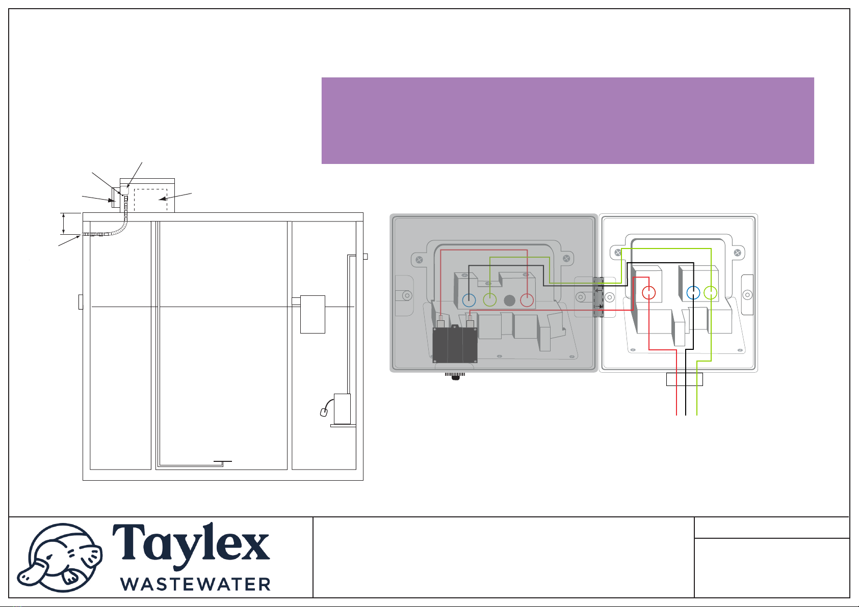
TITLE:
Control
Panel
25mm Electrical
Weather Proof
GPO’s
300mm
Taylex Electrical Connection Diagram
Coupling
Date: 08/06/2022
7amp Circuit
Breaker Reset
Switch
Nitto LA80B
Blower Box
TAYLEX
ABS ELECTRICAL
CONNECTION DIAGRAM
EARTH
(Green/Yellow Wire)
- BP Connect with
Taylex Earth
NEUTRAL
(Black/Blue Wire)
- BP Connect with
Taylex Neutral
(Blue Wire)
ACTIVE
(Red/Brown Wire)
- Connect at Centre
Hole of Isolator
Switch
Electrician
- Connect the incoming mains with the existing
wires that connect to the double GPO, ensuring the
correct polarity is maintained.
Weather Proof Single GPO
IMPORTANT INSTRUCTIONS
•Dedicated 10amp Circuit Breaker in power board (Taylex Best Practise)
•Hardwired with 2.5mm wire (ANE) Active, Neutral, Earth to Weatherproof GPO located in blower box
•Connect the 12V to 240V power supply plug to the single GPO
•Connect the 2 plugs (pump and blower) to the double GPO’s
•Turn all 3 GPO Switches ON
7amp Breaker (Pump & Blower)
No Connection Required - DO NOT REMOVE
This manual suits for next models
6
Table of contents
Popular Water Dispenser manuals by other brands


Elkay
Elkay EMABF8 1B Series Installation, care & use manual

Frigidaire
Frigidaire EFWC505 instruction manual

Hasley Taylor
Hasley Taylor HTHBHVR8 owner's manual

Flurida
Flurida FDFB10501 User instruction

Elkay
Elkay LVRCGRNTL8 1B Series Installation, care & use manual

Aerus
Aerus Origins WC400 Operation manual

Quench
Quench Bevi quick start guide

Watts
Watts PWSYS-WH-SOFT-PRO-SE - 30K Installation, operation and maintenance manual

Elkay
Elkay OBFATL8 1E Series Installation, care & use manual

Honeywell
Honeywell HWDT-620W owner's manual

Everpure
Everpure CGS-22 Specifications

Elkay
Elkay VRC8 1A Series Installation, care & use manual