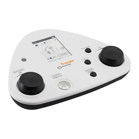
Taylor Hobson Surtronic Duo User manual

Error codes 䫭䇃ҷⷕ
The following error codes may appear on the
display during the course of using the Duo
Instrument. Before returning an instrument,
ensure that the batteries are not low.
E=1. Infra Red communication error - Repeat
operation.㑶䖲䫭䇃˗䞡ᮄ䖲
E=2. Measurement attempted when not
calibrated. Calibrate the TUޚҾ఼
E=3. Traverse Unit - Oscillator fault - If fault is
persistent, return to a Taylor Hobson Service
Centre. ᤃ㤵఼䫭䇃˗ᓎ䆂䖨ׂ
E=4. Traverse Unit - Motor Positioning fault - If
fault is persistent, return to a Taylor Hobson
Service Centre. 偀䖒ԡ㕂䫭䇃˗ᓎ䆂䖨ׂ
E=5. Traverse Unit - NVRAM Error - If fault is
persistent, return to a Taylor Hobson Service
Centre. NVRAM 䫭䇃˗ᓎ䆂䖨ׂ
E=6. Traverse Unit - Profile Over-range.
Re-attempt measurement.䕂ᒧ䍙䞣˗䞡䆩
E=7. Traverse Unit - Parameter Over-range.
Re-attempt measurement.খ᭄䍙䰤˗䞡䆩
E=8. Traverse Unit - Motor Speed Setup error.
Re-attempt Setup procedur偀䖒䗳ᑺ䆒㕂䫭䇃
E=9. Traverse Unit - Gain Setup error.
Re-attempt Setup procedure.Ⲟ䫭䇃
E=10. Control Unit - Oscillator fault - If fault is
persistent, return to a Taylor Hobson Service
Centre.ࠊܗ˖ᤃ㤵఼䫭䇃ˈᓎ䆂䖨ׂ
E=11. Traverse Unit - Calibration information
download error. Try again.ޚ䫭䇃ˈ䞡䆩
E=12. Traverse Unit - Not set up. Run the
Setup procedure.偅ࡼܗ˖䆒㕂
E=13. <Reserved>
E=14. : Traverse Unit - Electronic Measure-
ment error - If fault is persistent, return to a
Taylor Hobson Service Centre.⬉䏃䫭䇃ˈ䖨ׂ
Specification
Traverse length. 5mm (0.2in)偅ࡼ䭓ᑺ
Measurement length. 4mm (0.16in)⌟䞣䭓ᑺ
Traverse speed. 2mm/s (0.08in/s)⌟䞣䗳ᑺ
Gauge range. 200μm (8000μin)䞣
Gauge resolution. 0.05μm (2μin)ߚ䕼⥛
Display resolution:Ra. 0.01μm (0.4μin)
Display resolution: Rz, Rt*, Rp*, Rv*.
0.1μm (1μin)ᰒ⼎ߚ䕼⥛
Cut off. 0.8mm (0.03in) +/- 15%পḋ䭓ᑺ
Uncertainty. 0.1μm (4μin) or 5% of
result, to 95% confidence levelϡ⹂ᅮᑺ
Results range:Ra. 40μm (1600μin),
see ISO 4288-1996 ᳔5Dؐ
Results range: Rz, Rt*, Rp*, Rv*.
199.9μm (8000μin), see ISO 4288-1996
Stylus. Diamond, radius 5μm nominal , 90otip
angle, skid radius: 10mm nominal.⌟䩜
Filter type: 2CR, (200:1)Ⓒ⊶఼
Sample spacing: 1um䞛ḋ䯈䱨
Stylus Force. 10mN (1gf) max at mid range⌟
Batteries. Control Unit: One x 3V Lithium ⬉∴
2450. Traverse Unit: Three x 3V Lithium 2450
Units. μm or μinԡࠊ
Operating conditions. 10 to 35oC,
80%RH non-condensing⦃๗㽕∖
Size. 125mm x 80mm x 38mm
(4.92in x 3.15in x 1.5in)ሎᇌ
Weight. 200g (7oz)䞡䞣
*5 parameter model only.
Surtronic Duo
112-2916 (2 parameter model) and 112-3115 (5 parameter model)
Operator’s Leaflet K505-54
Issue 1.1 January 2002
Leicester, England
www.taylor-hobson.com
Declaration of Conformity
Manufacturer’s Name: Taylor Hobson Limited
Manufacturer’s Address: 2 New Star Road, Leicester, England, LE4 9JQ
It is declared that the product: Surtronic Duo
Conforms to all applicable requirements of BS EN 50081-1:1992, BS EN 50082-1:1998 and
BS EN 61010:2001.
The above product complies with the requirements of the EMC Directive 89/336/EEC as amended.
The above product complies with the requirements of the EMC Directive 73/23/EEC as amended.
Traverse Unit偅ࡼܗ Control Unitࠊܗ
Parameter Selectorখ᭄䗝ᢽ
Mode selectorᓣ䗝ᢽ
Start buttonsᓔྟᣝ䪂
Stylus⌟䩜
Mode statusᓣ
Parameter statusখ᭄
Displayᰒ⼎ሣ
On buttonᓔᴎᣝ䬂
IrDA windows㑶にষ
Marketing CHINA:TEL:86 (010) 82951585 82946733 FAX:86 010 58859230

Getting Started
Storage. The Surtronic Duo is supplied in its
storage configuration, that isTraverse Unit
connected to Control Unit. Before use, it is
necessary to separate the Traverse Unit from
the Control Unit.
Note: It is recommended that the unit is stored
in the storage configuration when not in use,to
prevent damage to the stylus.
Positioning. Position the
Traverse Unit on the surface
to be measured as shown.
There are two modes for operating the
Surtronic Duo:
Remote. In remote mode the Con-
trol Unit is positioned within 1m of the
Traverse Unit and data is passed
between the two units over the
IrDA link.
Note: The alignment
between the Traverse
Unit and Control Unit
must be maintained
during the measurement
process.
Connected. In connected mode
the Control Unit is connected to
the Traverse Unit as shown
before the measurement is made.
To connect the Control Unit to the
Traverse Unit, insert the Control
Unit as shown and tilt until the
latch engages.
Inserting the batteries
Remove battery covers as shown.
Insert new batteries, one 3V Lithium 2450 in the
Control Unit and three 3V Lithium 2450 in the
Traverse Unit. Replace the battery covers.
CAUTION: ONLY USE THE RECOMMENDED
BATTERIES. 䄺˖㤤Փ⫼ӣ䫖⬉
Battery Disposal
WARNING: DO NOT ATTEMPT TO RE-
CHARGE THE BATTERIES. USED AND OLD
BATTERIES MUST BE DISPOSED OF SAFE-
LY. DO NOT INCINERATE.
Switching on
If the Control Unit
is not used for five
minutes the unit
enters the power
saving mode, with
the display turned
off. Pressing any button will
reactivate the Contol Unit.
The Traverse Unit switches off completely after
five minutes without a new measurement. To
reactivate the Traverse Unit press the On
button. An LED flashes to confirm activation.
Low battery indicators: ⬉∴⬉Ԣ˖
Control Unit
battery low
Traverse Unit
battery low
Calibrate the gaugeޚ
Position the Traverse Unit to measure the
Calibration Standard supplied with the
instrument.偅ࡼܗᬒ㕂䜡ⱘ5DḋᵓϞˈ
ḋᵓ⿄ؐ5D ᖂ㉇
On the Control Unit press the Mode Select
buttons until is indicated on Mode status.
ࠊܗ䗝ᢽޚᓣˈᣝᓔྟ䬂ˈҾ఼㞾ࡼ
ᅠ៤ޚDŽ⊼ᛣ5D XP˗5] XPDŽ
Press the Start button on the Control Unit. This
will initiate the gauge calibration procedure.
The Control Unit will display the results of the
calibration. The Ra value should be 5.81μm
and the Rz value 21.5μm.
Measuring⌟䞣Operation of the Control
identical,
whether the system is in Connected or
Remote modes,
Position the
Traverse Unit on
the surface to be
measured. On the
Control Unit press
the Select
parameter button o select the parameter that is
required to be displayed upon completion of
measurement. Using the Select mode button
select either metric or imperial units as required.
To begin the
measurement press
either of the Start
buttons. The
‘measurement in
progress’ display is
as shown.
The measured
parameter is
displayed as shown.
If there is an error
the appropriate
error code is
displayed, see Error Codes.1)将驱动单元放置在
工件上,使测针接触被测表面
2)按模式选择键指示至um;
3)按开始键,仪器将执行测量
4)按参数选择键依次查看各参数结果
All parameters (not just the selected
parameter) are transmitted to the Control Unit
at the same time and temporarily stored. The
stored results may then be stepped through
using the select buttons.
lk
This manual suits for next models
2
