Sondar SF-500S User manual

SF-500S
*Please read this manual attentively before installation

© IS Technologies Co., Ltd. PAGE 2/ 129
Contents
ABOUT THIS MANUAL....................................................................................... 4
I. SAFETY GUIDE INSTRUCTION....................................................................... 6
1. Authorized Personnel .................................................................................................................... 6
2. Operation.......................................................................................................................................... 6
3. Cautions ............................................................................................................................................ 6
4. Product Inspection ......................................................................................................................... 6
5. Symbols............................................................................................................................................. 7
II
. PRODUCT......................................................................................................... 9
1. Principle of operation .................................................................................................................10
2. Specification ..................................................................................................................................11
3. Product Package ...........................................................................................................................13
4. Dimension ......................................................................................................................................15
III. INSTALLATION.............................................................................................18
1.
General Guide ..............................................................................................................................18
2. Controller installation..................................................................................................................19
3. Sensor Installation........................................................................................................................21
IV. WIRING ......................................................................................................... 26
1. Wiring..............................................................................................................................................26
2. Sensor Cable ..................................................................................................................................31
V. OPERATION ...................................................................................................33
1. Start-up Display ............................................................................................................................33
2. Display.............................................................................................................................................34
3. Buttons............................................................................................................................................39
VI. PROGRAMMING..........................................................................................42
1. LEVEL ...............................................................................................................................................42
2. FOW .................................................................................................................................................47

© IS Technologies Co., Ltd. PAGE 3/ 129
3. RELAY...............................................................................................................................................56
4. CURRENT OUTPUT .......................................................................................................................58
5. PULSE OUTPUT..............................................................................................................................61
6. COMMUNICATION SETUP ..........................................................................................................62
7. LOGGING SETUP ...........................................................................................................................64
8. SYSTEM SETUP ..............................................................................................................................66
VII. MAINTENANCE .......................................................................................... 73
1. Battery.............................................................................................................................................73
2. SENSOR ...........................................................................................................................................73
3. Firmware upgrading ....................................................................................................................74
4. Warranty Period............................................................................................................................75
5. Repair Service................................................................................................................................75
VIII. TROUBLE SHOOTING ...............................................................................77
ERROR CODE LIST .............................................................................................................................77
APPENDIX A. SF-500S MENU LIST ................................................................93
APPENDIX B. RS-232/RS-485 PROTOCOL.....................................................98
APPENDIX C. FLOW READER ........................................................................103
APPENDIX D. FLOW CHARTS........................................................................112

© IS Technologies Co., Ltd. PAGE 4/ 129
About this Manual
This manual provides important information about the installation, wiring,
operation, and control of SF-500S and its sensors; LXD-04. Please read this
manual before installing or operating the product. In addition to operating
the product, this manual is very important. Please keep it in a safe place for
easy reference.
This manual is provided an electronic version only. The electric version is
provided with the product package or it can be downloaded through our
website (www.sondar.com).
Please note that the contents of this manual are subject to change without
prior notice if the product is modified, upgraded or improved.
Although we have checked all contents of this manual but there would be the
possibility to remain errors. We welcome all suggestions for improvement.
SONDAR is a registered trademark of IS Technologies Co., Ltd.
Without our prior written permission, reproduction, distribution or any use
of manual contents are strictly prohibited.
Copyright IS Technologies Co., Ltd. 2013. All right reserved.

© IS Technologies Co., Ltd. PAGE 5/ 129
Safety Guide Instruction

© IS Technologies Co., Ltd. PAGE 6/ 129
I. Safety Guide Instruction
1. Authorized Personnel
The installation and operation of the product must be carried out by licensed
experts or qualified personnel. Please always wear protective equipment when
operating the products.
2. Operation
Before operating the unit, please read this manual thoroughly. The
manufacturer isn’t responsible accidents caused by user’s misuse or
modification of the product without manufacture’s permission. Conduct
periodic inspection of the product.
3. Cautions
This manual provides all information you need to operate SF-500S, maintain
and trouble shoot. Please follow the instructions. The manufacturer is not
responsible in any way for the risk of an accident when user doesn’tfollow
the instructions.
4. Product Inspection
When opening the product package box, look carefully to determine if the
products or accessories have been damaged or contaminated. If the product
has been damaged, it may not function properly.

© IS Technologies Co., Ltd. PAGE 7/ 129
5. Symbols
Caution:
If it is ignored, faults or malfunctions could be result.
Warning:
If it is ignored, injury to people and serious damage to
the instrument could be result.
Electric Shock
If it is ignored, the product could be damaged by
electric shock
Information:
It provides additional information.

© IS Technologies Co., Ltd. PAGE 8/ 129
Product Description
SF-500S | LXD-04

© IS Technologies Co., Ltd. PAGE 9/ 129
II
. PRODUCT
SF-500S is an ultrasonic non-contacting flow meter for open channels. The
measured level value is converted into the rate of flow in specific weirs or
flumes therefore the accurate level value is very important. LXD-04 is an
exclusive sensor for open channel flow, it provides accurate level reading.
SF-500S provides a variety of weirs and flumes formulations so it can be used
in different applications. The measured flow information is saved in the
memory of SF-500S and it can be downloaded by USB or transmitted by the
digital communication such as RS232, RS485 or Modbus.
Application:
LXD-Series sensors are suitable for liquids level monitoring in all industries,
particularly in the water and wastewater industry.
Weirs & Flumes
Parshall Flume
Suppressed Rectangular Weir
Contracted Rectangular Weir
V-Notch[Triangular]Weir
Cipolletti Weir
Leopold Lagco Flume
Palmer Bowlus Flume
H Flume
Trapezoidal Flume
•Compatible sensor is only LXD-04.
•XDS-300 sensor is not compatible with the SF-500S controller.
•Depending on the sensor material, the application can be restricted.
Before installing the sensor, please check the chemical compatibility
chart.

© IS Technologies Co., Ltd. PAGE 10 / 129
1. Principle of operation
LXD Sensor transmits ultrasonic pulses to the measurement target. The
pulses are reflected from the surface of the target and received back by the
sensor. The running time is converted into the distance and it is converted
the level. The measured level is also converted into flow rate according to the
selected primary measurement device of SF-500S.
D=(C•T)/2
D: DISTANCE
C: SOUND VELOCITY
T: TIME OF FLIGHT
•Distance: from the sensor bottom to surface of the target
•Level: from the bottom of storage to surface of the target
•Empty: from the sensor bottom to the bottom of storage

© IS Technologies Co., Ltd. PAGE 11 / 129
2. Specification
SF-500S (Controller)
Measurement Method Ultrasonic non-contacting
Measurement Range 0.00m3/h~200,000.00m3/h
Accuracy 0.2%of F.S
Resolution 1mm
Damping Rate 0.1m/min - 100m/min adjustable
Data Logging Period Maximum 672 days (1hr interval)
Output Analog Two Analog 4~20mA, max 750Ωisolated
3 Relays
Digital RS232, RS485, Modbus
Display Illuminated Graphic LCD
IP Rating IP65
Temperature -20℃~60℃(-4℉~140℉), 80%relative humidity
Material Polycarbonate
Dimension 166(W)×250(H)x95(D) mm
Weight ca. 2kg
Power Supply •100~230V AC±15%, 50/60Hz, 29VA(12W)
Fuse: 250V T1.0A
•DC 9~30V, Max 8W
LXD-04 (Sensor)
Range 0.3~4m (0.98- 13ft)
Bean Angle 8˚at -3dB
Process Connection 1” PF
Weight ca. 1.0kg
Material PVDF
Temperature -30℃~70℃(-22℉~158℉), 80%relative humidity
Temperature Compensation by a built-in temperature sensor
IP Rating IP68
Cable 2 Core Shield (AWG18)
Cable Extension up to 450m (1,476.3ft)

© IS Technologies Co., Ltd. PAGE 12 / 129
External Temperature Sensor
Type NTC, 10 kΩ
Temperature -30℃~70℃(-22℉~158℉)
Process Connection 1/8” PT
IP Rating IP68
Cable RG174
* The Specification is subject to change without prior notice.
© IS Technologies Co., Ltd. PAGE 13 / 129
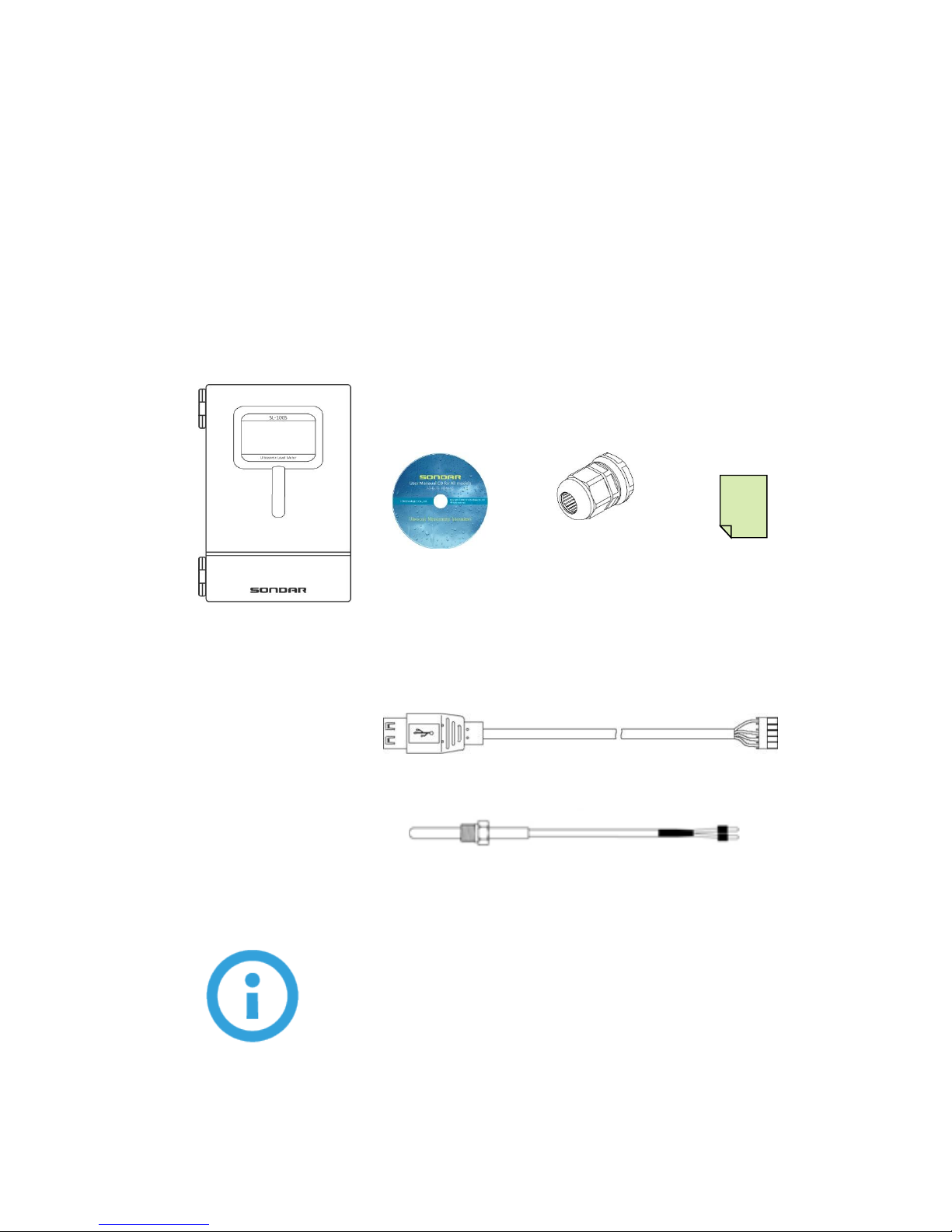
3. Product Package
SF-500S is a controller operated with the sensor, LXD-04. SF-500S and sensors
are packed respectively. Check all parts and the options are correct as it was
ordered.
3.1 Controller Box Package
Controller
(PG13.5 1EA)
(PG11.0 2EA)
Manual CD
Cable Grand X3
Test Report
USB Connector Cable
External Temperature Sensor (Option)
•The protection grade of SF-500S is IP65. It is valid before the cable
grand whole is made. When the product is delivered to the
customers, the cable grand wholes are made before the delivery
for user’s convenience.

© IS Technologies Co., Ltd. PAGE 14 / 129
3.2 Sensor Box Package
1”Adapter
(option)
Test Report
LXD-04
Flange(option)
Junction Box
(option)
Pipe (option)
•The basic cable length of the sensor is 1 meter. The cable length is
subject to change as an option if requested when ordering.

© IS Technologies Co., Ltd. PAGE 15 / 129
4. Dimension
4.1 Controller
1) The enclosure material is polycarbonate and the protection grade is IP65.
2) Using the whole in the back of the controller it is mounted on the wall.

© IS Technologies Co., Ltd. PAGE 16 / 129
4.2 Sensor
LXD-04 Sensor is an exclusive level sensor for SF-500S. Its range is 4meter
(13ft). The temperature is compensated by a built-in temperature sensor. The
sensor material is PVDF. Before mounting the sensor, check the chemical
compatibility chart if the sensor housing material is suitable for it.
LXD-04
106.5
90.5
87.4
67

© IS Technologies Co., Ltd. PAGE 17 / 129
INSTALLATION

© IS Technologies Co., Ltd. PAGE 18 / 129
III. Installation
1. General Guide
Before mounting the product, read this manual and specification. It is
installed in a place that is within the temperature range specified in this
manual and that is suitable to the enclosure rating and materials. If the
products are installed improperly, it may cause malfunction.
This is general guide for installing SONDAR products.
Remove the obstacles in the space between the sensor and the measured target
such as ladders, limit switches, heating spirals etc.
When mounting the sensor, keep the distance to the vessel wall.
The bottom of the sensor should be perpendicular to the surface of water.
Do not set the maximum level into the Dead Zone range.
Avoid the intense winds and excessive exposure to direct sunlight. The strong
winds change the path of ultrasound and may cause a malfunction. If you need
to install the unit in a spot exposed to direct sunlight, sun screen must be
installed.
Keep the distance from the place where are strong noise by high voltage, high
current etc.
Install the unit in the place vibration free.

© IS Technologies Co., Ltd. PAGE 19 / 129
2. Controller installation
2.1 Environment condition
In a place where ambient temperature is between -20 to +60 °C (-4℉~140℉)
In a place required minimum cable length.
In a place where it can be operated conveniently
In a place out of direct sunlight
In a place free from vibration
In a place that has sufficient space when its door is opened.
•Do not install near high voltage, current runs or variable
frequency motors.

© IS Technologies Co., Ltd. PAGE 20 / 129
2.2 Installation
Open the controller door and check the four screw holes.
Mark and drill four holes in the mounting wall.
Fasten the screw bolt by a screwdriver and mount the controller.
Check the controller leveled off on the wall.
Close the controller door.
This manual suits for next models
1
Table of contents
Popular Measuring Instrument manuals by other brands

HP
HP HP 70909A installation guide

MULTI MEASURING INSTRUMENTS
MULTI MEASURING INSTRUMENTS HWT-301 instruction manual

Calculated Industries
Calculated Industries Scale Master Classic user guide

Knick
Knick 830 R manual

Olympia
Olympia EKM 2000 owner's manual

EUTECH INSTRUMENTS
EUTECH INSTRUMENTS CON 700 - REV 2 instruction manual


