TAYO ZT1P52MI User manual

1/ 42
ZT1P52MI
Engine maintenance manual
2023-04-01

2/ 42
Foreword
All the materials, illustrations, photos, etc. Collected in this manual are compiled according to the latest product
of ZT1P52MI Euro IV. However, due to continuous improvement of products and changes in other aspects, there may
be some inconsistencies between your motorcycle and this manual. For parts upgrades, please refer to the part
codes on the official website of ZONTES which will not be listed in detail in this manual; if the names of parts in this
manual are inconsistent with the official website of ZONTES, the official website of ZONTES shall prevail.
If some contents of this manual are insufficient, please refer to the " driver's manual" attached to the
motorcycle. You can download the latest version of the driver's manual as a PDF in the corresponding model
introduction on the ZONTES official website.
©Guangdong Tayo Motorcycle Technology Co., Ltd.
All rights reserved
3/ 42
User Notice
This manual is compiled by Guangdong TAYO Motorcycle Technology Co., Ltd. And is used to guide dealers or service
personnel. This manual cannot provide more detailed knowledge about motorcycles, and is only for reference for maintenance.
If you do not have the corresponding knowledge such as electrician, machine repair, etc., improper assembly or maintenance
failure may occur during repai r.
If you need to clean or wash the body parts of this motorcycle, you should use neutral car wash liquid or tap water or diesel
oil, kerosene, etc. Acidic or alkaline car wash liquid will cause irreversible corrosion to the surface paint, electroplated surface,
anodized surface, etc. Of parts; gasoline will cause premature aging or hardening of sealants, gaskets, rubber parts, etc., reducing
the service life. It should be wiped with a non-woven cloth that will not leave residues. Ordinary rags may leave rags or wool that
will affect assembly or cause other adverse effects.
Our company tries to update this manual in a timely manner after product changes.
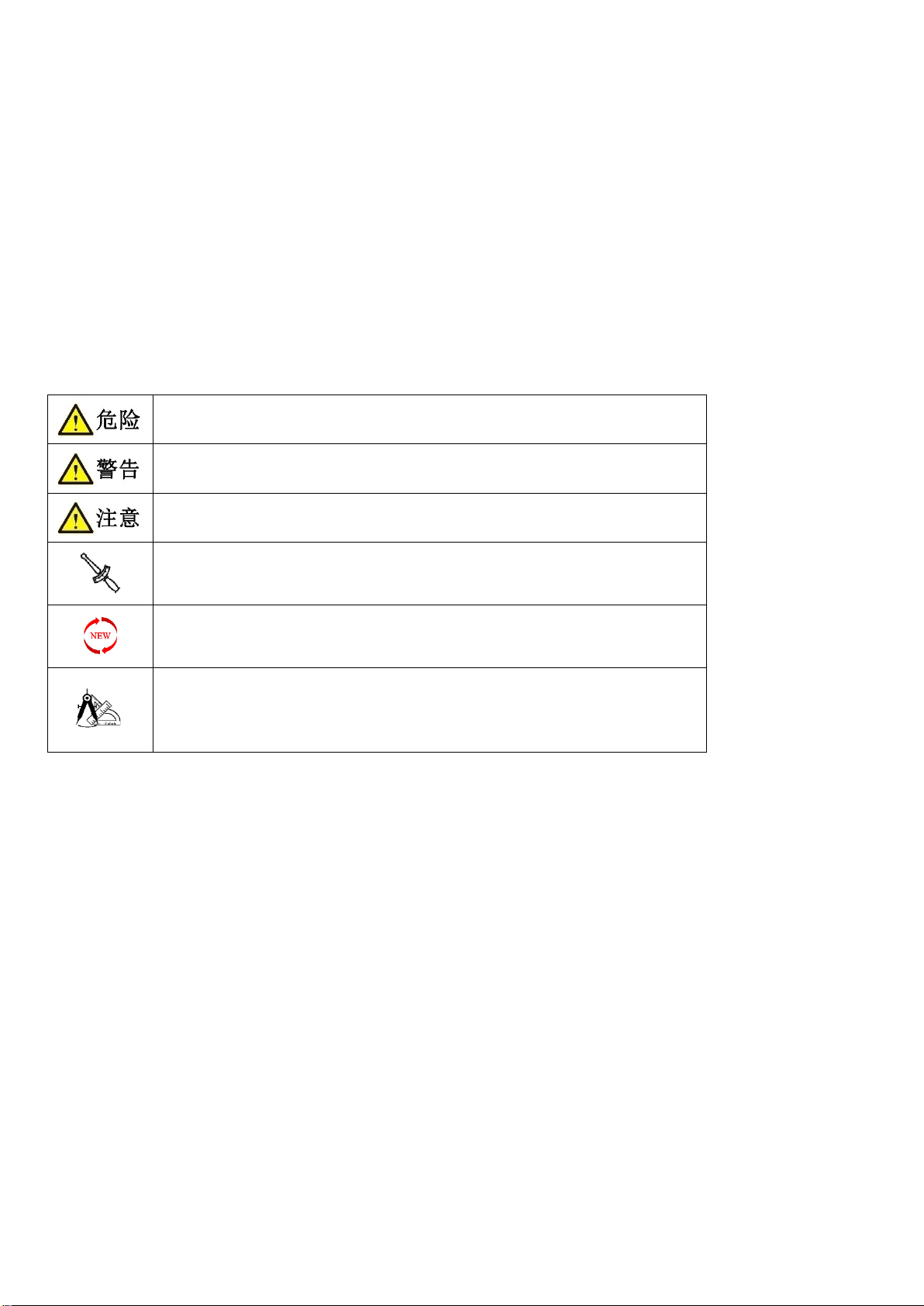
The following are the meanings of the icons marked in this manual:
Failure to comply will result in personal injury or death of the driver or maintenance
personnel ; or serious damage to spare parts , shortened service life, etc.
Failure to comply may result in personal injury or death of the driver or maintenance
personnel ; or damage to spare parts , abnormality, etc.
Failure to follow the warnings will result in personal injury to the driver or
maintenance personnel ; or matters requiring special attention during disassembly
Indicates that there is a requirement for torque
Indicates that the part needs to be replaced after disassembly
Indicates that the location needs to be measured

4/ 42
Table of contents
Table of contents ....................................................................................... 4
Spark plug ............................................................................................. 6
System components ................................................................................. 6
Cylinder compression test ............................................................................ 6
Water pump ........................................................................................... 7
System components ................................................................................. 7
Cylinder head cover, cylinder head.......................................................................... 9
System components ................................................................................. 9
Cylinder head cover ................................................................................ 11
Cylinder head ..................................................................................... 12
Camshaft ......................................................................................... 13
Guide bar ........................................................................................ 16
Tensioner ........................................................................................ 17
Cylinder, piston ........................................................................................ 18
System components ................................................................................ 18
Cylinder, piston .................................................................................... 19
Electric starter box cover, starter mechanism, timing chain ..................................................... 21
System components ................................................................................ 21
Electric starter box cover ............................................................................ 22
Start agency ...................................................................................... 23
Timing chain ...................................................................................... 23
Oil pump - right crankcase cover .......................................................................... 24
System components ................................................................................ 24
Right crankcase cover ............................................................................... 25
Oil pump ......................................................................................... 25
Oil filter .............................................................................................. 26
System components ................................................................................ 26
Oil filter .......................................................................................... 27
Magneto stator, rotor................................................................................... 27
System components ................................................................................ 27
Magneto rotor .................................................................................... 28
Magneto stator .................................................................................... 29
Left crankcase cover, continuously variable clutch sub-assembly ................................................. 30
System components ................................................................................ 30
Left crankcase cover ................................................................................ 30
Continuously variable clutch sub-assembly .............................................................. 31
Gearbox.............................................................................................. 33
System components ................................................................................ 33
Gear case cover.................................................................................... 35
Thermostat, radiator , fan case cover....................................................................... 38
System components ................................................................................ 38
Thermostat, radiator, fan case cover ................................................................... 39
Crankcase ............................................................................................ 40


6/ 42
Spark plug
System components
Remove the spark plug
1. Use the special spark plug socket -16# or the extended socket head -16# to remove the spark plug counterclockwise.
Check spark plugs
1. Check the thread of the spark plug and the center electrode. If there is any damage or deformation, replace the spark plug.
2. Use a feeler gauge to measure the gap a of the spark plug, if it exceeds the range, replace the spark plug.
Note: the standard value of spark plug gap is 0.7-0.9mm.
Install spark plugs
1. Screw the spark plug into the cylinder head, put on the spark plug special sleeve -16# or the extended sleeve head -16#, and
pre-tighten it with a torque wrench to fix the torque, the torque is 14±1 N.m.
Cylinder compression test
1. Start the engine, warm up the engine to normal operating temperature, and then turn off the engine.
2. Remove the dust near the spark plug and remove the spark plug.
3. Install the cylinder pressure gauge.
4. Fully open the throttle, press the start switch, and use the starter motor to drive the crankshaft and piston to run until the
cylinder pressure gauge reading stops rising (starter motor running time ≤ 15s).
Engine speed: 420-510r/min
Compression pressure: 440-550kpa (4.49-5.61 kgf/cm 2 , 63.8-79.8 psi)
① if the measured cylinder pressure is larger than the normal value, it means that there is carbon deposit on the top of the
piston or the wall of the cylinder.
spark plug
a
7/ 42
②if the measured cylinder pressure is lower than the normal value, pour a small amount of clean engine oil from the spark plug,
turn the crankshaft a few times, so that the piston ring and cylinder wall are evenly covered with oil film, and retest the cylinder
pressure. If the cylinder pressure measured after pouring oil is greater than the last cylinder pressure value, please dismantle the
machine and check the piston and piston ring.
5. Use the spark plug tool to install the spark plug in place and tighten it with a fixed torque (fixed torque: 14±1 N.m).
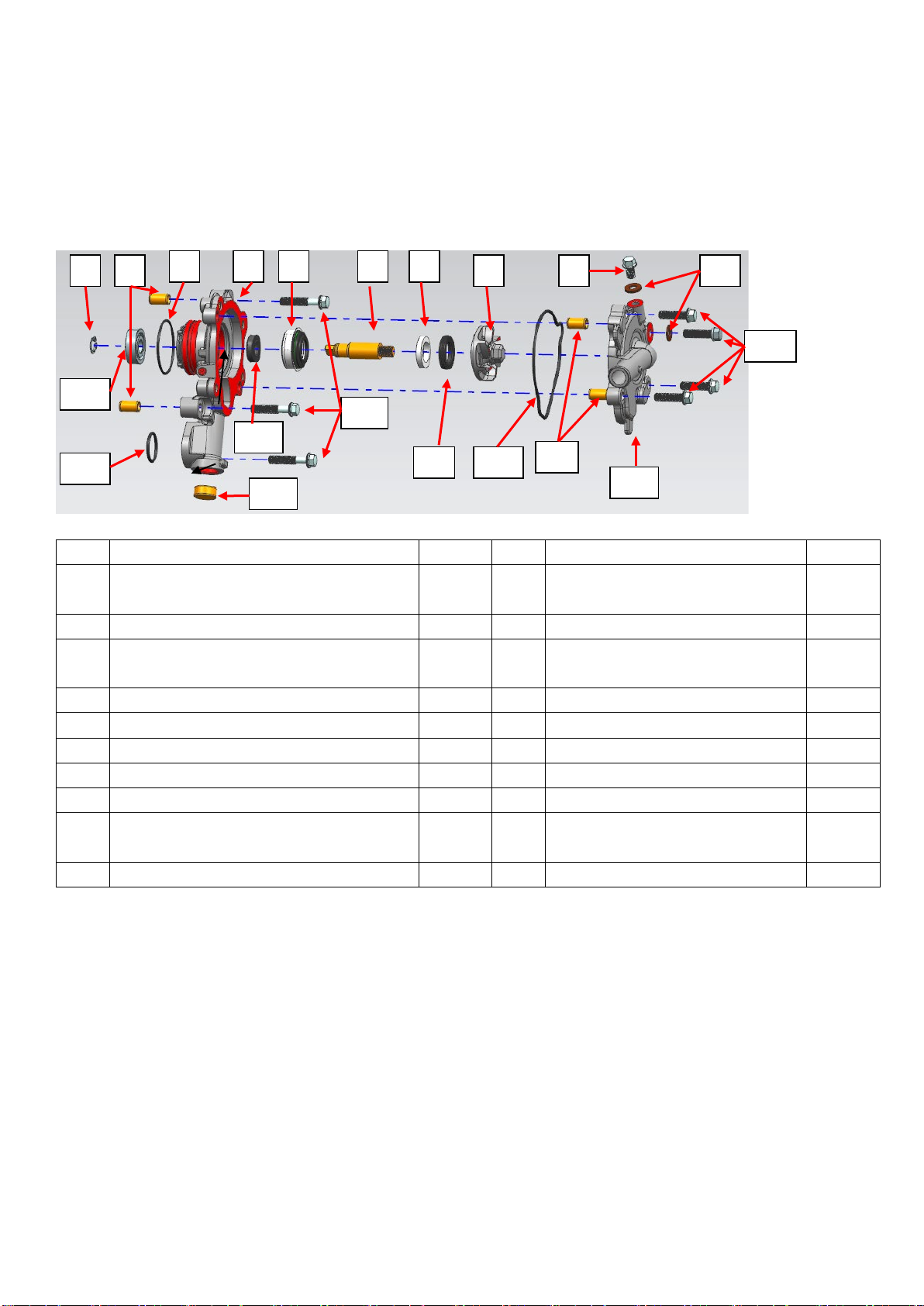
Water pump
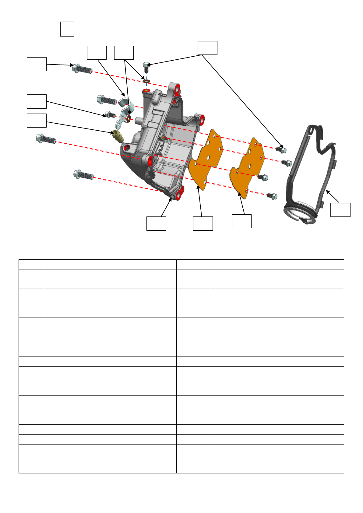
System components
No. Part name Quantity No. Part name Quantity
1 Gb894.1 shaft retaining ring φ10 (oxidized
black)
1 11 M6×22 hexagon flange fully threaded
bolts (grade 8.8/zinc)
4
2 Φ8×14 hollow positioning pin 4 12 ZT1P58MJ water pump cover 1
3 Φ36×1.9 acrylic O-ring 1 13 ZT1P58MJ
water pump cover sealing
ring
1
4 ZT1P58MJ water pump housing 1 14 Water seal moving ring rubber 1
5 Water seal static ring 1 15 M6×30 hex flange bolts 3
6 ZT1P58MJ water pump shaft 1 16 Fb12×20×5 fluorine rubber oil seal 1
7 Water seal moving ring ceramics 1 17 ∅16.5×7.5 water plug 1
8 ZT1P58MJ water pump blade 1 18 18.2×2.4 EPDM rubber O-ring 1
9 M6×10 top pin bolt (zinc)1 19 Gb/t 276-6000-p5c3 deep groove ball
bearings
1
10 6.3×12×1.6 copper gasket 2
Assembly
1. Remove 3 m6×30 hexagonal flange bolts counterclockwise with a torque wrench (or air batch) and an extended outer hexagon
socket -8#, remove the water pump from the engine, and then remove the φ36×1.9 acrylic o-type ring, 18.2×2.4 EPDM O-ring
and two φ8×14 hollow positioning pins.
2. Use a torque wrench (or air batch) and an extended outer hexagon socket -8# Assembly 4 m6×22 hexagonal flange
full-threaded bolts and 1 m6×10 top pin bolt (zinc) on the water pump cover counterclockwise. Zinc), remove the water pump
cover, water pump cover sealing ring, 2 copper gaskets and 2 φ8×14 hollow positioning pins.
3. Use a 12# wrench to rotate counterclockwise to loosen and remove the water pump blade, and take out the water seal moving
ring ceramic and water seal moving ring rubber.
Take out the water pump shaft, use a flat-blade screwdriver to extend from the bearing hole until it contacts the water seal, and
then tap it slowly to knock out the water seal.
1
2
18
3
17
19
14
8
7
6
5
15
16
4
10
2
11
12
13
9
8/ 42
Use a flathead screwdriver to pry out the oil seal, and then knock out the bearing to complete the disassembly of the water
pump. (note: when the water pump is running normally without failure, it is not recommended Assembly the water pump,
internal bearings, oil seals, and water seals.)
Inspection
1. Check the water pump cover ring and 18.2×2.4 O-ring on the water pump cover . If there are any defects such as wear and
edge trimming, replace the O-ring with a new one to prevent water leakage due to poor sealing .
2. Check whether the threads of the water pump blades and the water pump shaft are slippery.
3. Check the water pump shaft and blades for cracks, damage, wear, etc. If they are defective, replace them with new ones.
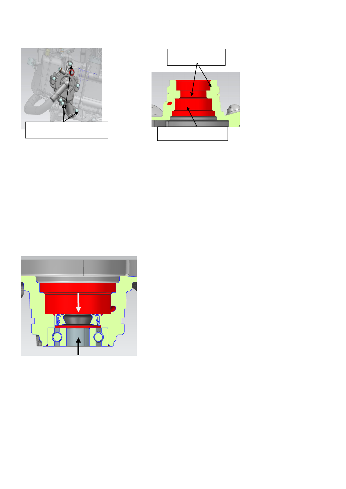
Install
1. Take a new fb12×20×5 fluorine rubber oil seal and press it to the position shown in the figure below. After installation,
measure the depth to confirm whether it is installed in place.
Remarks: ① apply engine oil to the oil seal installation hole and install the oil seal.
②fb12×20×5 fluorine rubber oil seal pressing depth: the distance from the end face of the oil seal to the joint surface of the
pump cover is 23.4 (-0.2,0) mm or the end face is even.
2. Check whether the bearing rotates smoothly. If the bearing rotates stuck, replace it with a new one. After oiling the bearing
hole, use a special pressure head to press the bearing into place.
Note: bearing model: gb276-6000/p5c3 deep groove ball bearing.
3. Take a new water seal, check to make sure that the surface of the water seal is clean and free of debris, apply 962t
bowl-shaped plug sealant on the hole where the water seal is installed, and press the water seal in place with the special
pressure head for installing the water seal.
M6×30 hex flange bolts
Apply 962T sealant
anointed with oil
9/ 42
4. Put the water-sealed moving ring rubber into the inner hole of the water pump blade; put the water-sealed moving ring into
the inner ring of the water-sealed moving ring rubber (the crossed side faces inward, and the smooth side faces outward), and
apply an appropriate amount of silicone oil on the smooth surface of the moving ring;
Screw the water pump impeller assembly into the water pump shaft (apply thread glue), lock it with a 12# sleeve, and correct
the torque with a torque wrench , torque: 20±1.5 N.m.
5. Apply a small amount of engine oil to the water pump shaft and put it into the water pump casing, install it in place and install
the retaining ring for the shaft. (note: apply a proper amount of water-soluble silicone oil on the static ring and moving ring of
the water seal)
6. Take two φ8×14 hollow positioning pins and put them into the corresponding holes, put the water pump cover sealing ring on
the water pump cover groove (if the O-ring is trimmed or worn, replace it with a new one), and finally take 4 m6× 22
full-threaded bolts on the hexagonal flange surface (grade 8.8/zinc) , one of which is inserted into a 6.3×12×1.6 copper gasket,
and tightened clockwise with a torque wrench (or air batch) and an extended outer hexagonal sleeve -8# bolt. Torque standard:
12±1.5N·m.
7. Take a m6×10 top pin bolt (zinc), insert a 6.3×12×1.6 copper gasket, screw the bolt into the threaded hole at the
corresponding position, torque wrench (or wind batch) and extend the outer hexagonal sleeve cylinder-8# tighten the bolts
clockwise. Torque standard: 10±1 N·m. (note: the copper gasket is a one-time consumable, and a new gasket is required for
installation)
8. Install the φ36×1.9 acrylate O-ring and the 18.2×2.4 EPDM O-ring into the corresponding positions.
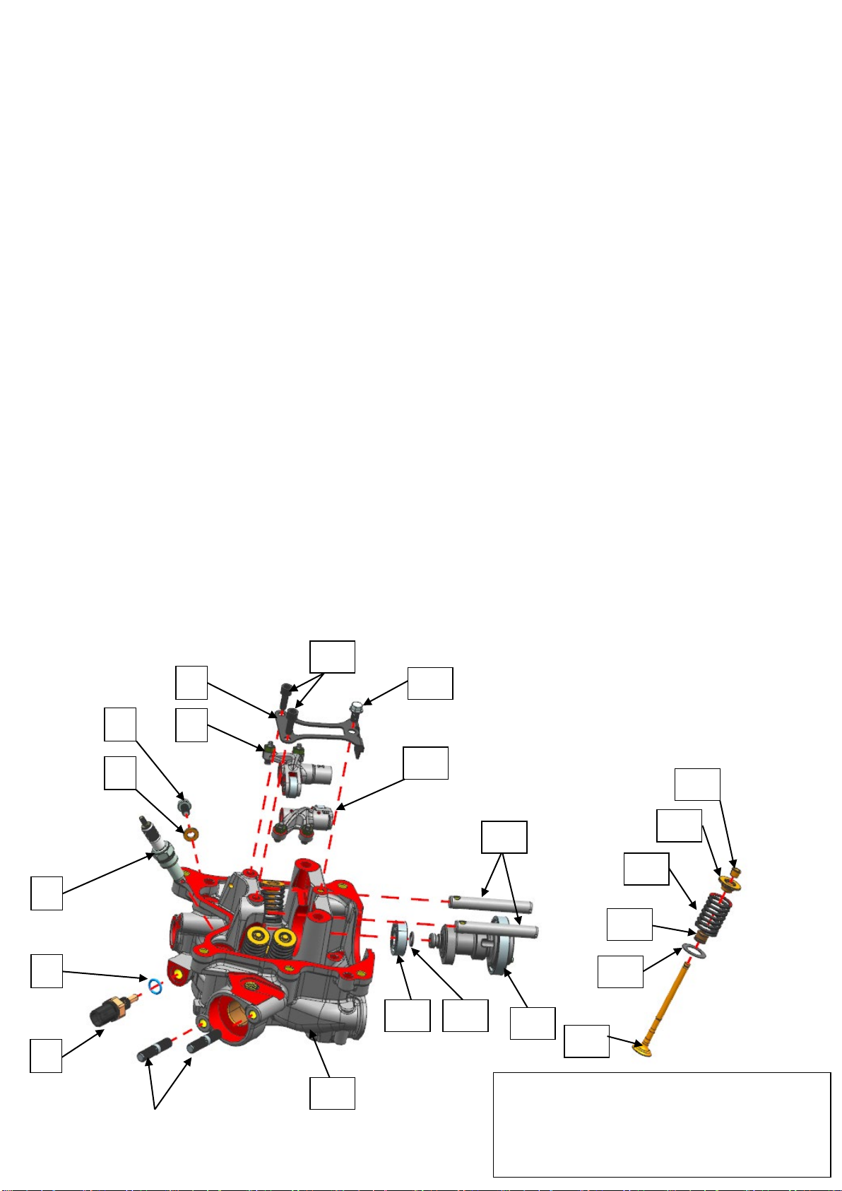
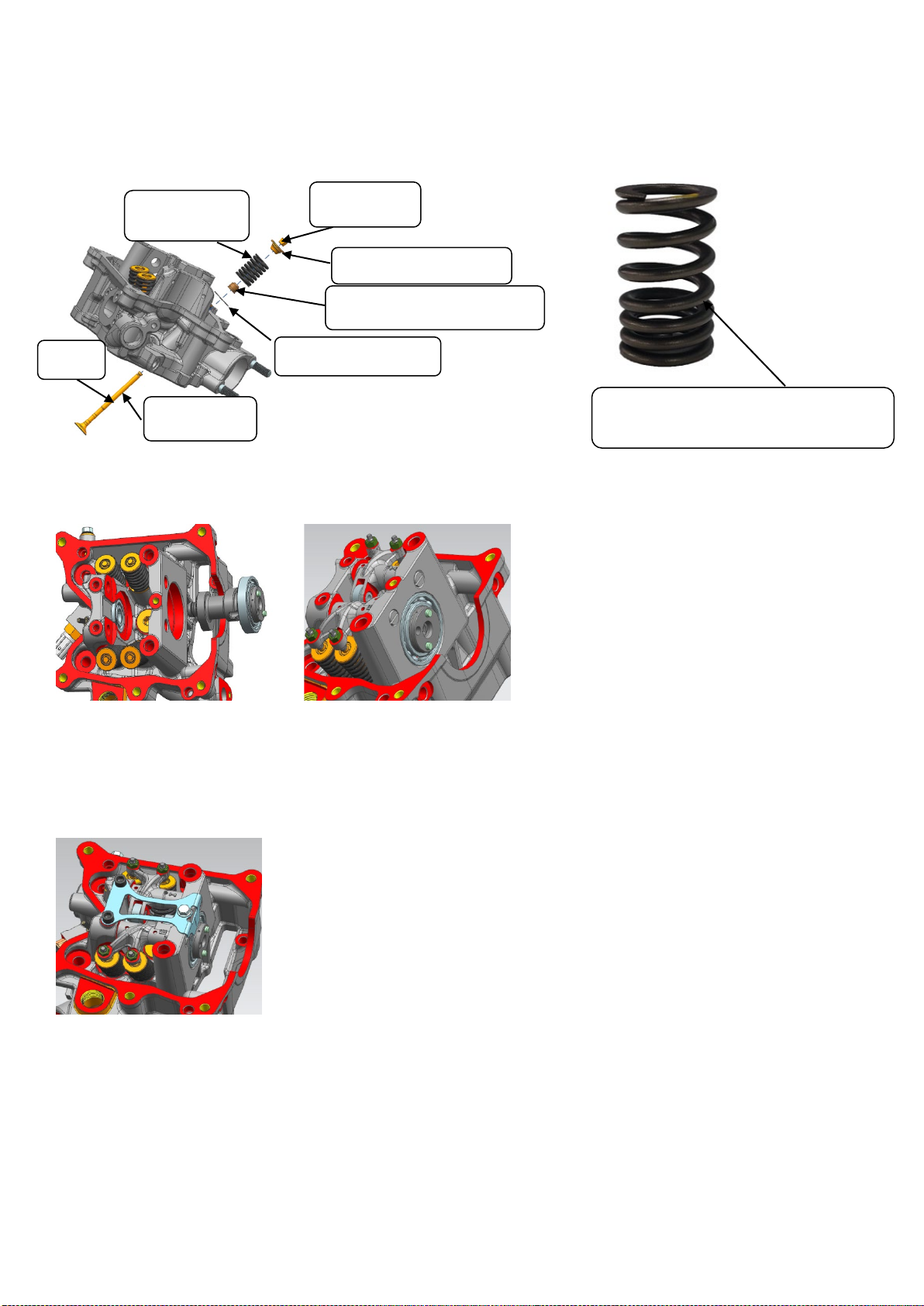
Cylinder head cover, cylinder head
System components
6
5
4
3
2
20
15 13
14
10
11
21
Refer to the figure for disassembly and
assembly of the valve, the disassembly
structure of the intake valve and exhaust valve
is the same.
12
19
18
17
22
7
8
16
9
10/ 42
Parts information
No. Name Quantity Name
1 Aym8-m8×38 double-headed 10.9 grade stud
(zinc )2 Tool: stud socket m8fixed torque: 20±2 N.m
Thread fastening glue
2 Water and oil shared sensor 1 Tools: 17# socket and fixed torque wrench fixed
torque: 14±1N.m
3 9×2 EPDM rubber O-ring 1
4 Cr8ei spark plug (protruding type) 1 Tool: 16# spark plug socket fixed torque: 14 ± 1
N.m
5 6.3×12×1.6 copper gasket 1
6 M6×10 top pin bolt (zinc)1 Tool: t-sleeve-8# fixed torque: 10±1 N.m
7
ZT1P58MJ intake rocker arm subassembly-b
1
8 ZT1P58MJ camshaft bearing pressure plate 1
9 M5×15-5# hexagon socket head screw 2 Apply thread glue, tool: 5# inner hexagon fixed
torque: 7±1 N.m
10 M6×10 top pin bolt (zinc)1
Apply thread glue, tool: t-sleeve-8# fixed torque:
10±1 N.m
11 ZT1P58MJ exhaust rocker arm subassembly-b 1
12 ZT1P58MJ intake and exhaust rocker shaft 2
13 ZT1P58MJ camshaft sub-component-b 1
14 8.8×1.9 fluorine rubber O-ring 1
15 Gb276-6001/p5c3 deep groove ball bearings
(nitrided) 1
1
30 31
29
27
26
24 23
32
28
25
11/ 42
16 ZT1P58MJ cylinder head 1
17 ZT1P58MJvalve Into 2 row
2
18 13.2×20.8×0.5 valve spring seat 4
19 Φ 5.0 valve rod diameter oil seal 4
20 ZT1P58MJ exhaust valve spring 4
Twenty
one ZT1P58MJ valve spring bearing plate 4
Twenty
two ZT1P58MJ valve lock clip 8
Twenty
three M6×10 top pin bolt (zinc)5 Tool: t-sleeve-8# fixed torque: 10±1N.m
Twenty
four 6.3×12×1.6 copper gasket 2
25 Zt1p72mn cylinder head cover tubing clamp 1
26 Gb16674m8×25 bolt 4 Tool: t-sleeve-10# fixed torque: 20±2.5 N.m
27 M6×10 top pin bolt (zinc)1 Tool: t-sleeve-8# fixed torque: 10±1N.m
28 ZT1P58MJ cylinder head cover air balance tube 1
29 ZT1P58MJ cylinder head cover 1
30 ZT1P58MJ cylinder head cover labyrinth cover
gasket 1
31 ZT1P58MJ cylinder head cover labyrinth cover
plate 1
32 ZT1P58MJ cylinder head cover rubber pad
subassembly 1
Cylinder head cover
Assembly
Gb16674 M8×25 bolts diagonally at t-rod -10#, and remove the cylinder head cover, cylinder head cover rubber pad, and φ 8×14
hollow positioning pin in sequence.
Note: when removing the cylinder head cover, the water pump needs to be removed first.
Inspection
1. Check that the cylinder head cover rubber pad on the cylinder head cover is not scratched or damaged. If it is scratched or
damaged, it needs to be replaced.
Install
1. As shown in the figure, after removing the plane sealant, oil stains and dust on the joint surface of the cylinder head and the
cylinder head cover, apply an appropriate amount of plane sealant on the position shown in the figure. Check the cylinder head
cover sealing ring on the cylinder head cover. After confirming that the installation is in place, install the cylinder head cover
assembly to the corresponding position of the cylinder head. The rubber pad of the cylinder head cover should not be misplaced.
Use four m8×25 bolts to secure the cylinder head cover is pre-tightened and tightened with a fixed torque, 20 ± 2.5N.m.
12/ 42
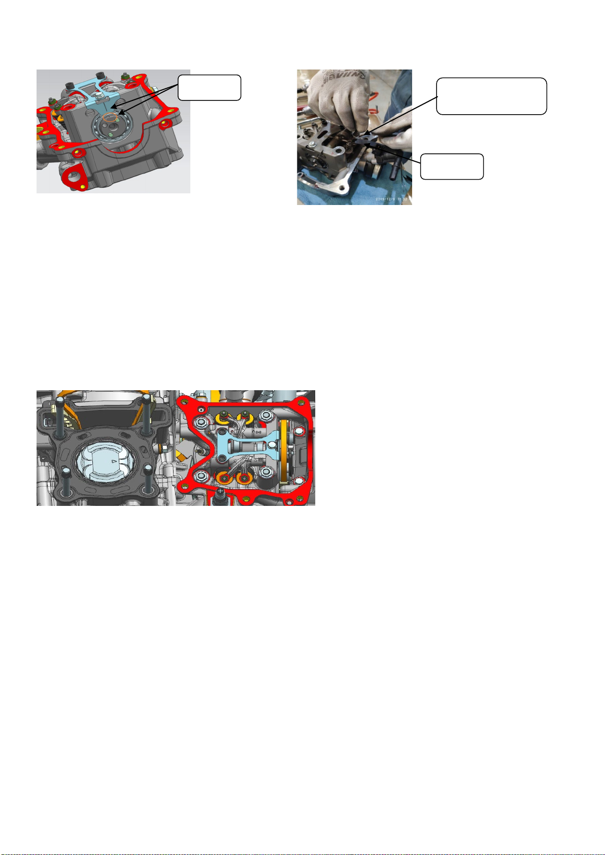
Cylinder head
Assembly
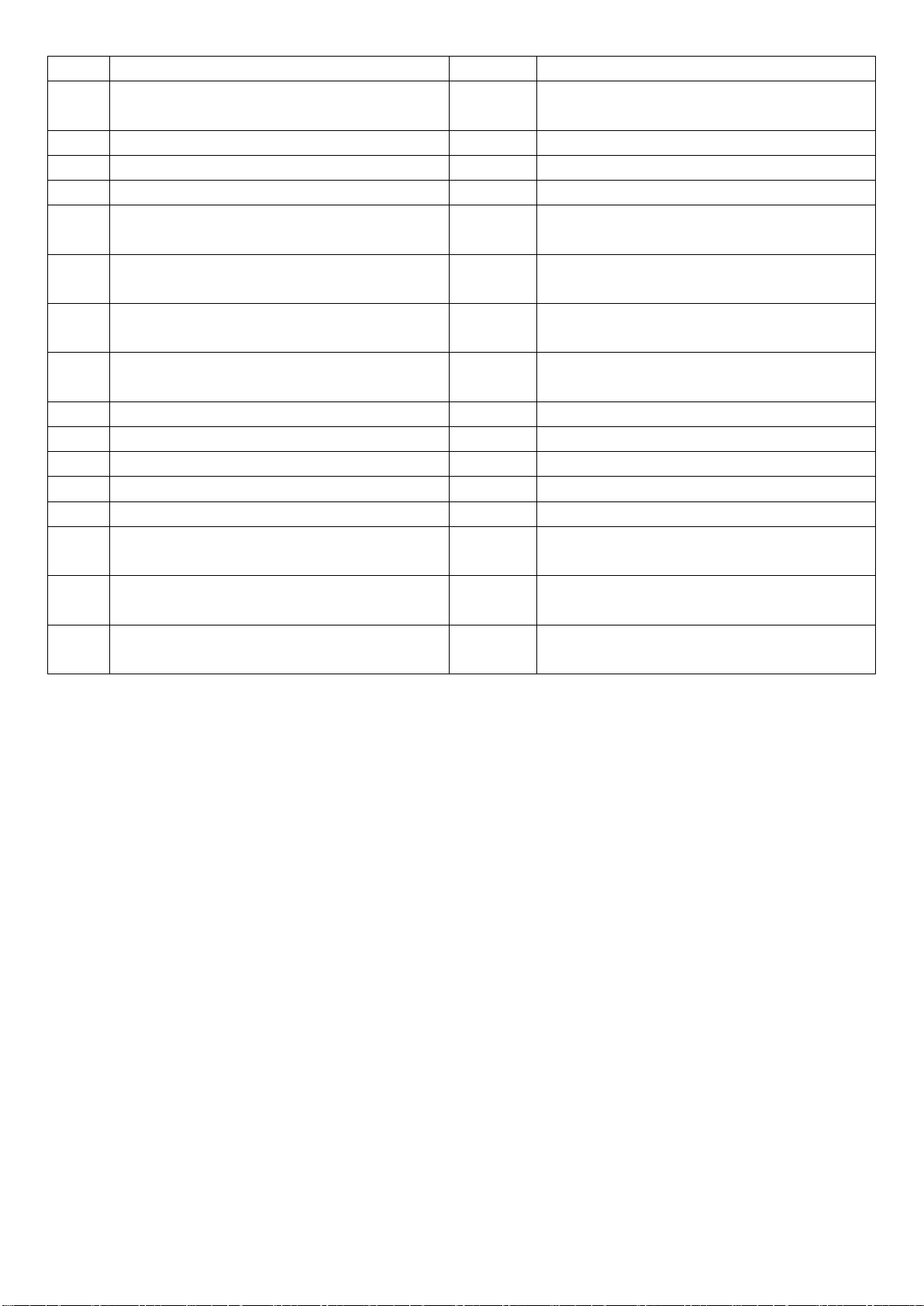
1. Use a t-shaped sleeve -8# to remove the thermostat bolts, remove the thermostat, and remove the radiator and fan case
cover (refer to the ZT1P52MI engine maintenance manual for disassembly and assembly - thermostat, radiator, fan case
cover).
2. Put the 17#-t-shaped sleeve on the lock bolt of the magneto rotor, and then turn the crankshaft clockwise so that the marking
line at point t on the flywheel aligns with the arrow position in the figure. At the same time, the top dead center marking line on
the timing driven sprocket should also be aligned with the marking line on the camshaft bearing pressure plate.
Note: when turning the flywheel, once the marking line at point t turns over the marking line, it cannot be rotated in the
opposite direction. It is necessary to turn the crankshaft clockwise two times again to re-align the point! ! !
3. As shown in the picture, remove the tensioner with t bar-8#, remove the camshaft bolt with the jackhammer + sleeve head
14#, remove the timing driven sprocket, and the decompression lever (tensioner refer to ZT1P52MI engine maintenance
manual for disassembly and assembly--cylinder head cover, cylinder head-tensioner).
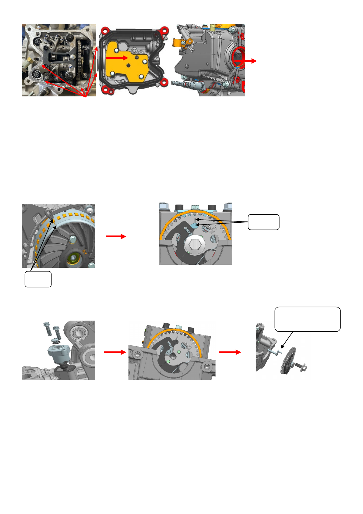
4. As shown in the picture, first use t-bar-8# to remove 2 pieces of m6×105 hexagonal flange bolts on the side of the cylinder
head, and then use t-bar-12# to remove 4 pieces of m8×1.25 lock nuts on the opposite corners of the cylinder head, take off the
cylinder head, cylinder head gasket and positioning pin (note: the removed cylinder head gasket cannot be used again) .
align
align
Decompression
lever
apply sealant
13/ 42
Camshaft
Assembly
1. Remove the cylinder head pressure plate bolts, and take out the cylinder head pressure plate, rocker shaft, intake and exhaust
rocker arms, and camshaft.
2. Use the valve spring removal and installation tool to remove the valve lock clip (do not over compress the valve spring). After
taking out the valve lock clip, remove the valve spring retainer, valve spring, valve stem diameter oil seal (the removed valve
stem diameter oil seal cannot be used again), valve spring seat, and valve in sequence.
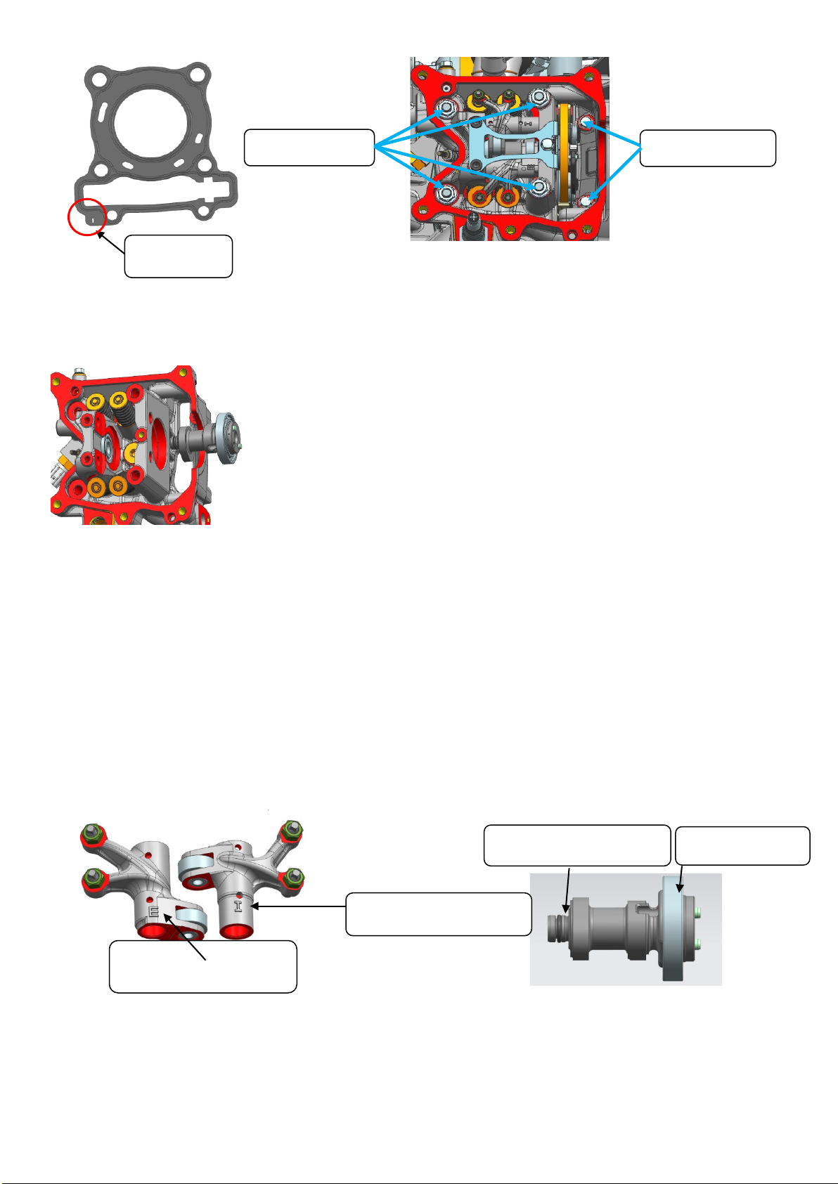
Inspection
1. Check that there is no bump or scratch on the joint surface of the cylinder head;
2. Check that there is no abnormal wear on the intake and exhaust rocker shafts;
3. Check that the intake rocker arm (mark I) and the exhaust rocker arm (mark E) have no abnormal wear, and the rollers of the
intake and exhaust rocker arms rotate smoothly without abnormal noise;
4. Check that the intake and exhaust springs have no cracks or abnormal wear;
5. Check whether the camshaft is abnormally worn, and the fluorine rubber O-ring is not damaged or trimmed. Turn the
camshaft bearing by hand, and it should rotate smoothly without abnormal noise.
6. Check whether the diameter of the valve stem is abnormally worn, bent or ablated, and whether the valve can move smoothly
in the valve guide; check whether the surface of the valve seat is abnormally worn or ablated; ablation;
7. Check the cylinder head bearing. The inner ring of the bearing should rotate smoothly without any stagnation. If the inner ring
of the bearing is stuck, please replace the cylinder head bearing.
camshaft bearing
Fluorine rubber O-ring
Exhaust rocker arm logo
Intake rocker arm logo
M6×105 bolts
M8×1.25 nut
Identifier I
14/ 42
Install
1. As shown in the figure, install the valve (apply oil), valve spring seat, valve stem diameter oil seal (press in place after
installation), valve spring, valve spring retainer, and valve lock clip (install with valve installation tool) in sequence ( note: remove
dust and foreign matter from the valve seat surface and cylinder head seat surface. When installing the valve spring, the
sparse ring faces upward and the dense ring faces downward ).
2. Install the camshaft (O-ring needs to be installed), the intake rocker arm sub-assembly, the exhaust rocker arm sub-assembly,
and the intake and exhaust rocker arm shaft in order (rotate the rocker arm shaft so that the slot is in a horizontal position).
(note: O-rings cannot be missed on the camshaft)
3. As shown in the figure, install the camshaft bearing pressure plate, apply an appropriate amount of thread fastening glue on
the surface of 1 m6x10 and 2 m5x15 bolts, after screwing in, pre-tighten and set the torque, the torque is: m6 bolt torque 10±1n.
M , m5 bolt torque 7±1N.m .
Valve clearance
1. As shown in the figure, adjust the valve clearance: align the camshaft groove point with the scale line of the camshaft bearing
pressure plate, insert the feeler gauge between the valve adjustment bolt and the end face of the valve stem, pull the feeler
gauge by hand, and take out the plug after the clearance is qualified. Take a no. 8 torx wrench and put it on the lock nut on the
valve clearance adjustment screw, fix the adjustment screw with a special t-type wrench, and then tighten the nut with a torx
Valve Valve spring seat
Valve rod diameter oil seal
Valve spring retainer
valve spring
Sparse circles face up, dense circles
face down
apply oil
Valve lock
15/ 42
wrench to ensure that the intake and exhaust valve clearances are within the specified range of standard values. (valve clearance
adjustment nut torque: 9±1N.m intake valve clearance: 0.10mm - 0.14mm exhaust valve clearance: 0.18mm - 0.22mm)
Cylinder head installation
1. Remove the oil stains, water stains and dust on the joint surface of the cylinder and the cylinder head. After checking that
there are no foreign objects on the surface of the cylinder and piston, install 2 φ10 positioning pins and cylinder head gaskets
(note: cylinder head gaskets cannot be repeated. Use. After the cylinder head has been disassembled, the gasket of the
cylinder body box needs to be replaced, and the joint surface needs to be coated with flat sealant. For the installation of the
cylinder piston, refer to the ZT1P52MI engine maintenance manual - cylinder, piston).
2. As shown in the figure, after confirming that there is no missing or wrong installation, install the cylinder head into the
corresponding position of the engine. After evenly diagonally pre-tightening the cylinder head nut and the two locking bolts on
the side, use the fixed torque wrench to tighten respectively (nut φ8.3×φ17×2 iron gasket should not be missed, m8×1.25
hexagonal flange nut fixed torque 25 ± 3 N.m, m6×105 hexagonal flange bolts with a fixed torque of 12 ± 1.5 N.m).
3. As shown in the figure, check the marked line of the t point of the flywheel, and the marked line of the t point is aligned with
the position of the arrow. At the same time, the top dead center marking line on the timing driven sprocket should also be
aligned with the scale line of the camshaft bearing pressure plate, install the decompression lever and the timing sprocket, and
use the flywheel limit tooling to fit the crankshaft on the upper limit of the magneto rotor. Tighten and torque the camshaft bolts
with a wind gun + sleeve head 14#, torque: 30±2N.m, and install it into the tensioner.
Remarks:
1. After confirming that the timing chain has not fallen off from the timing drive gear, tighten the timing sprocket at a constant
torque, and after installing the tensioner, turn the crankshaft to recheck the timing for the second time.
2. After the camshaft bolts are tightened to a fixed torque, move the decompression mechanism of the driven sprocket. The
decompression mechanism should rebound quickly, and if it is not stuck, it is qualified.
align
8# wrench
Feeler

16/ 42
Guide bar
Assembly
1. Before removing the guide bar, the following parts need to be removed.
·Water pump. (refer to ZT1P52MI engine maintenance manual for disassembly and assembly - water pump)
·Tensioner. (refer to ZT1P52MI engine maintenance manual for disassembly and assembly--cylinder head cover, cylinder
head-tensioner)
·Cylinder head cover parts. (refer to ZT1P52MI engine maintenance manual for disassembly and assembly--cylinder head cover,
cylinder head-cylinder head cover)
·Cylinder head assembly. (refer to ZT1P52MI engine maintenance manual for disassembly and assembly--cylinder head cover,
cylinder head-cylinder head)
2. Remove the guide bar.
Inspection
1. Check the guide bar for excessive wear or damage.
Install
1. As shown in the figure, install the guide bar. (note: after the guide bar is installed in place, the convex point of the guide bar is
lower than the joint surface of the cylinder block and cylinder head.)
align
Insert the guide bar into the limit card slot
17/ 42
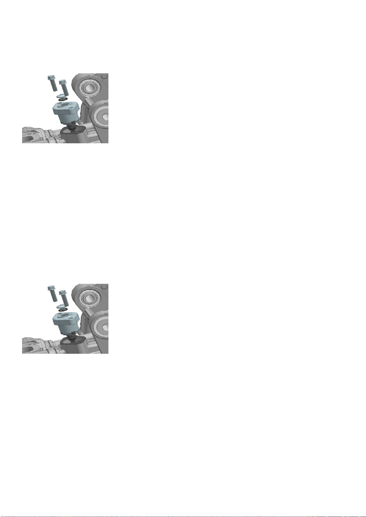
Tensioner
Assembly
1. As shown in the picture, use a cross batch to remove the cross bolts and O-rings on the top of the tensioner, then use the
T-bar -8# to evenly loosen the tensioner fixing bolts diagonally, and remove the tensioner and the tensioner pad piece.
Inspection
1. When the top rod of the tensioner is normally extended, press the fixed rod of the tensioner by hand, if the top rod cannot
rebound, it is qualified;
2. Check that the O-ring is not scratched or damaged. If it is scratched or damaged, it needs to be replaced.
Tensioner installation
1. Tighten the tensioner ejector rod with a one-word batch (rotate the one-word batch clockwise while holding the tensioner
ejector rod with your hands), and tighten it when it reaches the highest point, and the ejector rod can be locked automatically.
Put the tensioner gasket into the tensioner and place it in the corresponding position of the cylinder, and tighten it with m6×22
bolts at a fixed torque with a torque of 1 2 ± 1.5N.m. (tensioner spacers cannot be reused)
2. Rotate the ejector bolt counterclockwise with a flat batch, and after confirming that the ejector rod of the tensioner pops up,
put in the O-ring and the cross bolt to tighten.
18/ 42
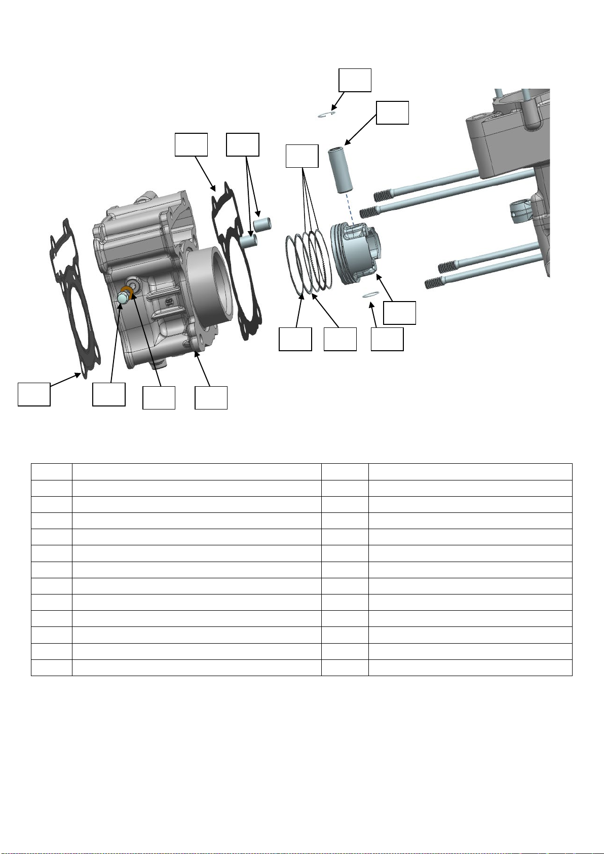
Cylinder, piston
System components
Parts information
No. Material name Quantity Remark
1 Cylinder 1
2 6.3×12×1.6 copper gasket 1
3 M6×10 top pin bolt 1 Tool: t-sleeve-8# fixed torque: 10±1 N.m
4 Cylinder head gasket 1 Cannot be reused
5 Cylinder block gasket 1 Cannot be reused
6 Φ 10×14 hollow positioning pin 2
7 Oil ring combination 1
8 16×1 piston pin retaining ring 2 Needle nose pliers
9 14×37×8.5 piston pin 1
10 Piston 1
11 Second ring 1
12 Top ring 1
12
4
7
5 6
12 11
9
10
3
8
8

19/ 42
Cylinder, piston
Assembly
1. Gently pull out the cylinder, and hold the piston and connecting rod with your hands;
2. Remove the piston pin retaining ring with needle-nose pliers, push the piston pin out of the small head hole
of the connecting rod, and remove the piston (note: prevent the piston pin retaining ring from falling into the
box);
3. Remove the cylinder block box gasket.
Remarks:
①the piston is turned to the top dead center before disassembly.
②do not drop the timing chain into the crankcase.
③ when the cylinder is pulled out of the piston, fix the piston and connecting rod by hand or other auxiliary tools to avoid
collision with the box and cause damage.
Inspection
1. Check the cylinder inner wall and piston skirt:if there are obvious scratches or wear on the inner wall of the
cylinder and the piston skirt, the defective parts must be replaced;
2. Check whether the three piston rings are abnormally worn ( if there is abnormal wear , the corresponding parts need to be
replaced ).
Disassemble the piston ring
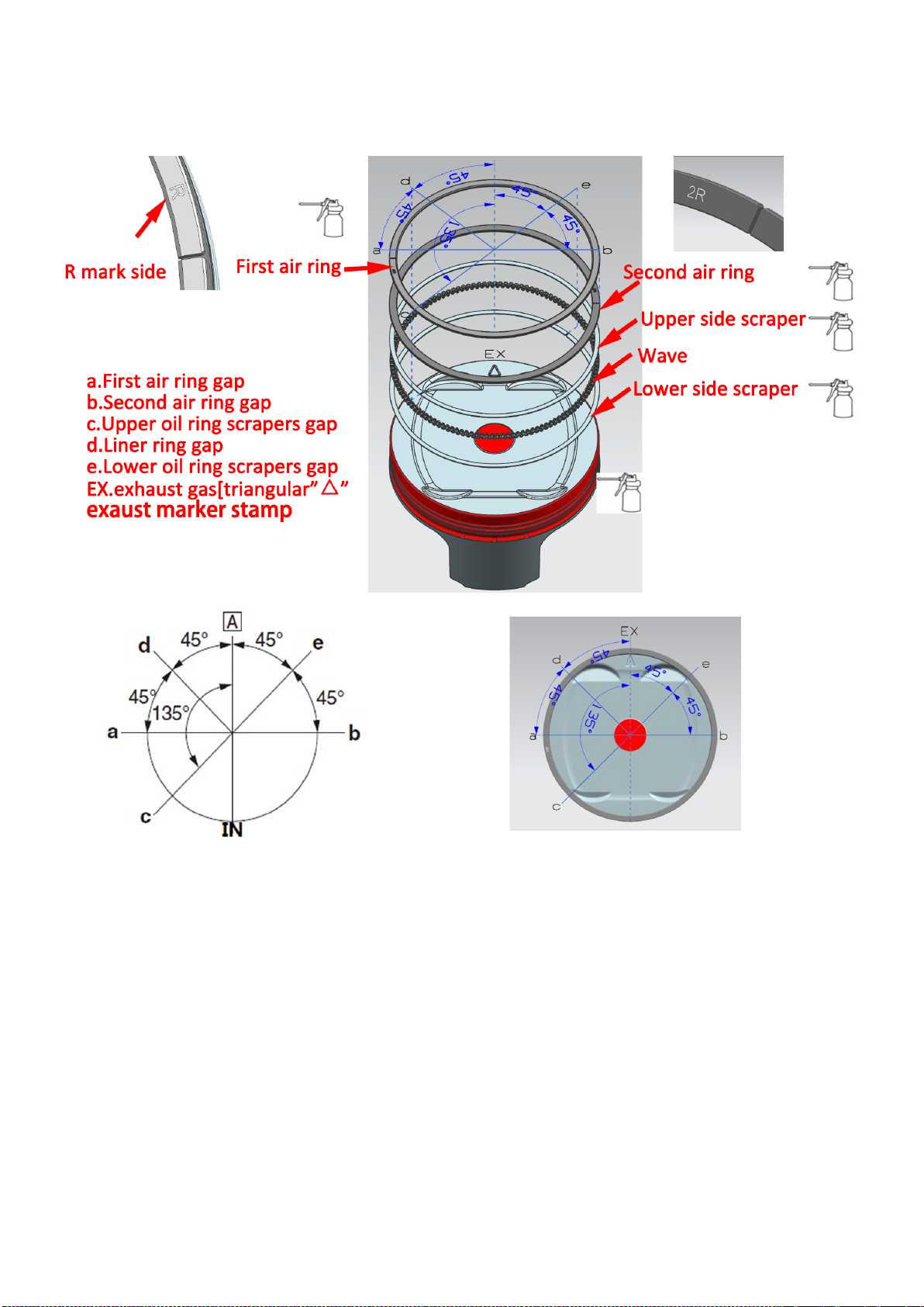
1. Remove the combination of the first air ring, the second air ring and the oil ring.
Tip: To remove the piston ring, open the end notch by hand and lift the other side of the ring over the top of the piston.
Install the piston ring
1. Remove the carbon deposits on the piston ring groove and the piston ring, and apply an appropriate amount of engine oil to
the piston ring groove;
2. Put the oil ring assembly into the piston oil ring groove.
Remarks:
① do not use the first air ring and the second air ring interchangeably.
②when installing the gas ring, the side with the marked face faces up (piston top).
③installing the oil ring assembly, first install the wave-shaped lining ring (the arc of the end surface of the wave-shaped
lining ring faces downward), then install the lower side scraper ring, and finally install the side scraper ring.
④ the notch " a " of the first ring is on the left side of the "△" ex mark, along the axial direction of the piston pin; the notch "
b " of the second ring is on the right side of the "△" ex mark, and the angle with " a " is 180 °; the lower side the notch " e " of
oil ring scraper is at 45 ° between "△" ex and " b " ; the angle between " c " and " e " of upper oil ring scraper is 180 °; the
2R/RN marking
id
piston skirt
20/ 42
notch " d " of oil ring backing is at "△" on the left side of ex , perpendicular to the line connecting " c " and " e ". (as shown in
the picture below)
Install the cylinder and piston
1. Place two hollow positioning pins and install a new cylinder block gasket (as shown in the figure, before installing the new
cylinder block gasket, ensure that the assembly plane of the cylinder block is smooth and flat and at the assembly plane of the
cylinder body apply flat surface sealant).
2. Install the cylinder block, press the piston ring by hand to fit it into the cylinder block; the openings of the piston ring are
staggered for assembly (the arrow on the top of the piston points to the exhaust side as shown in the figure).
Remarks: ① before installing the cylinder block, apply an appropriate amount of engine oil evenly on the inner wall of the
cylinder block.
②apply proper amount of engine oil to the piston skirt and piston ring.
③do not drop the timing chain into the crankcase.
3. Put the piston pin into the piston and install it on the connecting rod, install the piston pin retaining ring into the ring groove
with needle-nose pliers (one piston pin retaining ring at each end of the piston pin), and then gently push the cylinder to the
assembly position.
Remarks: ① apply an appropriate amount of engine oil to the piston pin hole and the small end hole of the connecting rod.
Table of contents


