TBA KM5S-LCD User manual

USERS GUIDE
KM5S–LCD

5
CONTENTS
ABOUT THE USER MANUAL 9
APPEARANCE AND SIZE 10
MATERIAL AND COLOUR 10
FUNCTION SUMMARY AND BUTTON DEFINITION 11
FUNCTION SUMMARY 11
MONITOR AREA 12
BUTTON DEFINITION 12
OPERATION CAUTIONS 12
INSTALLATION INSTRUCTION 14
NORMAL OPERATION 14
POWER ON/OFF 14
DISPLAY INTERFACE 15
PUSH CRUISE CONTROL 15
TURN ON/OFF BACKLIGHT 16
PAS LEVEL SELECTION 17
BATTERY INDICATOR 17

6
MOTOR POWER MONITOR 18
ERROR CODE INFORMATION 18
USER SETTING 19
PREPARATION BEFORE STARTING 19
GENERAL SETTING 19
TRIP DISTANCE AND TRIP TIME CLEARANCE 19
BACKLIGHT CONTRAST 20
POWER-ON PASSWORD ENABLE/DISABLE 21
POWER-ON PASSWORD ENABLE 21
POWER-ON PASSWORD MODIFY 22
NORMAL PARAMETER SETTING 22
WHEEL DIAMETER SETTING 23
SPEED-LIMIT SETTING 24
PERSONALIZED PARAMETER SETTING 25
PASSWORD TO ENTER THE PERSONALIZED SETTING MODE 25
BATTERY POWER BAR SETTING 26
PEDAL ASSISTANT LEVEL SETTING 27
PEDAL ASSISTANT LEVEL SELECT 27
PAS RATIO MODIFY 29
CONTROLLER OVER-CURRENT CUT SETTING 30
PEDAL ASSISTANT SENSOR SETTING 30
DIRECTION OF PEDAL ASSISTANT SENSOR SETTING 31
SENSITIVITY OF PAS SETTING 31

7
PROPORTION PARAMETER SETTING OF PAS 32
SPEED SENSOR SELECTION 32
THROTTLE DEFINITION 33
THROTTLE ENABLE/DISABLE 33
THROTTLE LEVEL ENABLE/DISABLE 34
SYSTEM SETTING 34
DELAY TIME SETTING OF BATTERY POWER 35
MAX SPEED LIMIT 35
BUTTON PUS SETTING 36
PAS SPEED SETTING 37
SLOWLY START UP SETTING 37
INTERFACE OF SLOWLY SETTING UP 38
EXIT SETTING 38
RECOVER DEFAULT SETTING 38
FAQ 41
BARCODE 41
QUALITY ASSURANCE AND WARRANTY SCOPE 42
CONNECTION LAYOUT 43
VERSION HISTORY 44

8
APPENDIX 45
ATTACHED LIST 1:ERROR CODE DEFINITION 45
ATTACHED LIST 2:PASSWORD TABLE 46
ATTACHED LIST 3:PERSONALIZED PARAMETER SETTING 47
ATTACHED LIST 4:POWER ASSIST TABLE 48
ATTACHED LIST 5:SYMBOL DEFINITION 49

9
About the User Manual
Dear users,
To ensure the best performance of your e-bike,
please read through the KM5S product introduction
carefully before using it. We will detail all steps including:
hardware installation, setting up software and normal
operation of the display. The introduction will also help
you to resolve the possible confusion or malfunctions.

10
Appearance and Size
Material and Colour
KM5S products are made of PC plastic. This material
ensures normal operation & robust mechanical
performance in the temperature range of -20℃to 60℃.
Real product and dimension figure (unit: mm)

11
Function Summary and Button Definition
Function summary
KM5S provides a wide range of functions and
indicators to fit the user’s needs. The indicator contents
are as follows.
◆Battery indicator
◆Motor power ratio
◆Speed display (including running speed, max speed
and average speed)
◆Trip distance and total distance
◆Time display of single trip
◆Cruise control
◆Headlight on/off
◆Error code indicator
◆Various parameters setting (like:wheel size, speed
-limiter, battery level bar, PAS level, controller limited
current, max speed, password enable, ect...)
◆Recover default setting

12
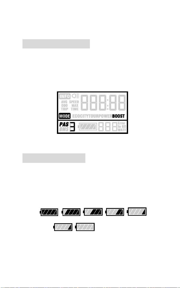
Monitor Area
Monitor Area
Button definition
KM5S has three buttons. They are . In
the following introduction, is named as “MODE”.
is named as “UP” and is named as “DOWN”.
Operation Cautions
Take care to use safety. Don’t attempt to release the
connector when the battery is powered on.

13
Try to avoid hitting.
Don’t remove the waterproof sticker to avoid
affecting the waterproof performance.
Don’t modify system parameters to avoid
suboptimal performance.
Take the display to be repaired when the error
code appears.

14
Installation Instruction
Fix the display onto the handlebar and adjust to an
appropriate visual angle. Tighten all the screws &
connectors.
Normal Operation
Power on/off
Long press MODE button (for 2 seconds) then the
display & controller will. With the display on, long press
MODE to turn off the power supply to the e-bike. When
turning the display off, both the display & controller will
shut down. The leakage current is less than 1 uA.
When parking the e-bike for more than 10
minutes, the display will shut down
automatically.
15
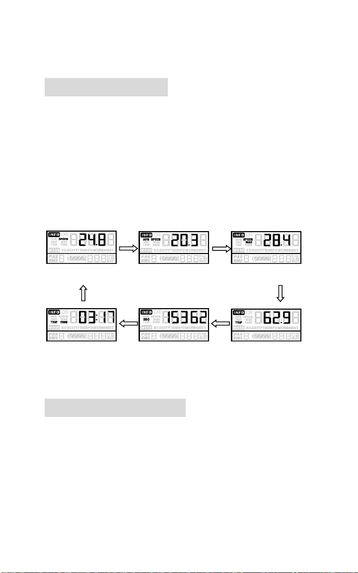
Display interface
After starting up the display, the default display is
running speed. Short press MODE to change the
indicated information in sequence as follows: Running
speed (Km/h) → Average speed (Km/h) → Max speed
(Km/h) → Trip distance (km) → Total distance (km) →
Travel time → Running speed (Km/h).
Running speed Average speed Max speed
Trip time Trip distance Total distance
Push cruise control
Hold DOWN for 2 seconds to start power assistant
walk. The e-bike will move at a uniform speed of 6 Km/h.
PUS shows on the screen.

16
Push cruise control
6Km/h “Push Cruise Control” function should
only be used while pushing the e-bike by hand.
Please don’t use this function when riding.
Turn on/off backlight
Hold UP for 2 seconds to turn on the backlight of the
display, the headlight (if installed) will be power on at
the same time. Hold UP for 2 seconds again, to turn off
the headlight and the backlight.
Turn on/off backlight
17
PAS level selection
Short press UP/DOWN to change the output power
of the motor. The power ranges from level 1 to level 5.
Level 1 being the minimum power & level 5 the
maximum power. The default value is level 1.
PAS level
Battery indicator
The 5 battery bars represent the capacity of the
battery. When the battery has low voltage, battery
frame will flash to indicate that the battery needs to be
recharged immediately.
Low voltage flash
Battery indicator

18
Motor power monitor
Motor power showed as below:
Error code information
If there is something wrong with the electronic
control system, the error code will appear automatically.
Detail information of the error codes can be found in
Table 1.
Error code
Take the display to be repaired when error
code appears.

19
User Setting
Preparation before starting
Make sure all connectors are plugged in and the
cables are without damage.
General setting
Long press the MODE button to start the display,
and then hold both UP and DOWN for 2 seconds to enter
the setting menu.
Trip distance and trip time clearance
TC means trip clearance. Press UP or DOWN to
choose yes or no respectively to clear the trip
information.
Trip distance and trip time will be cleared
at the same time.

20
Trip distance clearance
Backlight contrast
BL means backlight. Level 1 is the low brightness,
level 2 is the middle brightness & level 3 is high
brightness. The default level is 1. Bottom of the screen
displays SET2.
Short press UP or DOWN to modify the backlight
brightness. Long press MODE to confirm the
modification and exit the general setting.
Backlight Brightness

21
Power-on password enable/disable
The character “-P-” on the bottom of the screen
designates the password page. Hold both UP and DOWN
for 2 seconds to enter normal settings and then hold
both UP and MODE for another 2 seconds to enter the
power-on password enable/disable page.
Press UP/DOWN to change the number & press
MODE to enter digits one by one. After the correct
4-digit password is entered, press MODE to confirm then
select password enable or disable.
Password entering page
Power-on password enable
Press UP/DOWN to select Y or N, and press MODE
to confirm. Power-on password default is N.
Y= Power-on password enabled
N= Power-on password disabled

22
Password disable page
Power-on password modify
Use UP and DOWN to change the number, and short
press MODE is to select the digits one by one, finally long
press MODE to confirm the modification.
Password modify page
Normal parameter setting
Hold both UP and DOWN for 2 seconds to enter
User settings. Then hold both DOWN and MODE for over
2 seconds & enter the password 0512 to modify the

23
current parameters
Use the same method described in the previous
section to enter the password 0521.
Password inputting page
Wheel diameter setting
Press UP and DOWN to select the correct value to
match the wheel diameter. Selectable values include: 16”,
18”, 20”, 22”, 24”, 26”, 700C, 28”.Default diameter is
26inchs.
Ld means Wheel Diameter.
Wheel diameter setting page
Table of contents


