StumpJumper EVO S1 User manual
EVO
USER MANUAL


CONTENTS
1. INTRODUCTION ......................................................................................................................................... 1
1.1. INTENDED USE ....................................................................................................................................................................................................1
1.2. WARRANTY ..........................................................................................................................................................................................................1
2. GENERAL NOTES ABOUT ASSEMBLY........................................................................................................ 2
2.1. FORK/HEADSET...................................................................................................................................................................................................2
2.2. SEATPOST ...........................................................................................................................................................................................................2
2.3. BOTTOM BRACKET ............................................................................................................................................................................................3
2.4. REAR AXLE..........................................................................................................................................................................................................3
2.5. SEATSTAY ............................................................................................................................................................................................................3
2.6. BULKHEAD AND DOWNTUBE PROTECTOR...................................................................................................................................................3
2.7. STEM.....................................................................................................................................................................................................................4
3. GENERAL NOTES ABOUT MAINTENANCE.................................................................................................. 5
4. SPECIFICATIONS...................................................................................................................................... 6
4.1. GEOMETRY ..........................................................................................................................................................................................................6
4.2. GENERAL SPECIFICATIONS..............................................................................................................................................................................7
4.3. SHOCK CUSTOMIZATION..................................................................................................................................................................................7
4.4. TOOLS REQUIRED ..............................................................................................................................................................................................7
4.5. BOLT SIZE / TOOLS / TO TORQUE SPECIFICATIONS.....................................................................................................................................7
4.6. GENERAL TORQUE SPECIFICATIONS .............................................................................................................................................................8
4.7. BEARING SPECIFICATIONS ...............................................................................................................................................................................8
4.8. SPACER/AXLE/BOLT SPECIFICATIONS...........................................................................................................................................................8
5. INTERNAL ROUTING ................................................................................................................................. 11
5.1. DROPPER SEATPOST .........................................................................................................................................................................................11
5.2. INTERNAL GUIDE TUBES ..................................................................................................................................................................................11
5.3. SHIFT/BRAKE HOUSING....................................................................................................................................................................................15
5.4. HEAD TUBE ICR PORT .......................................................................................................................................................................................16
6. REAR TRIANGLE PIVOT ASSEMBLY .......................................................................................................... 16
6.1. BEARING ASSEMBLY ..........................................................................................................................................................................................17
6.2. PIVOT ASSEMBLY...............................................................................................................................................................................................18
6.3. SUSPENSION TORQUE SPECIFICATIONS.......................................................................................................................................................22
7. FLIP CHIPS ............................................................................................................................................... 23
7.1. ADJUSTING THE HORST PIVOT FLIP CHIP.......................................................................................................................................................23
7.2. ADJUSTING THE HEADTUBE ANGLE ...............................................................................................................................................................24
8. AIR SHOCK SETUP ................................................................................................................................... 27
8.1. SETTING AIR PRESSURE....................................................................................................................................................................................27
8.2. ADJUSTING REBOUND ......................................................................................................................................................................................27
8.3. ADJUSTING COMPRESSION .............................................................................................................................................................................27
9. DERAILLEUR HANGER .............................................................................................................................. 28
10. SWAT BLADDER...................................................................................................................................... 29
We may occasionally issue updates and addendums to this document. Please periodically check
www.specialized.com or contact Rider Care to make sure you have the latest information.
Info: specialized.com / 877-808-8154
SPECIALIZED BICYCLE COMPONENTS
15130 Concord Circle, Morgan Hill, CA 95037 (408) 779-6229
0000153163_UM_R1, 05/20

1
1. INTRODUCTION
This user manual is specific to your Specialized Stumpjumper EVO bicycle. It contains
important safety, performance and technical information, which you should read before your
first ride and keep for reference. You should also read the entire Specialized Bicycle Owner’s
Manual (“Owner’s Manual”), because it has additional important general information and
instructions which you should follow. If you do not have a copy of the Owner’s Manual, you
can download it at no cost at www.specialized.com, or obtain it from your nearest Authorized
Specialized Retailer or Specialized Rider Care.
Additional safety, performance and service information for specific components such as
suspension or pedals on your bicycle, or for accessories such as helmets or lights, may
also be available. Make sure that your Authorized Specialized Retailer has given you all
the manufacturers’ literature that was included with your bicycle or accessories. If there is
a difference between the instructions in this manual and the information provided by the
component manufacturer, please refer to your Authorized Specialized Retailer.
When reading this user manual, you will note various important symbols and warnings, which
are explained below:
WARNING! The combination of this symbol and word indicates a potentially
hazardous situation which, if not avoided, could result in serious injury or
death. Many of the Warnings say “you may lose control and fall.” Because
any fall can result in serious injury or even death, we do not always repeat
the warning of possible injury or death.
CAUTION: The combination of the safety alert symbol and the word CAUTION
indicates a potentially hazardous situation, which, if not avoided, may result in
minor or moderate injury, or is an alert against unsafe practices.
The word CAUTION used without the safety alert symbol indicates a situation
which, if not avoided, could result in serious damage to the bicycle or the
voiding of your warranty.
INFO: This symbol alerts the reader to information which is particularly
important.
GREASE: This symbol means that high quality grease should be applied as
illustrated.
CARBON FRICTION PASTE: This symbol means that carbon friction paste
should be applied as illustrated to increase friction.
TORQUE: This symbol highlights the correct torque value for a specific bolt.
In order to achieve the specified torque value, a quality torque wrench must
be used.
TECH TIP: Tech Tips are useful tips and tricks regarding installation and
use.
1.1. INTENDED USE
The Specialized Stumpjumper Evo bicycles are intended and tested for Mountain Bike
(condition 4) use only. For more information on the intended use and structural weight limits
for the frame and components, please refer to the Owner’s Manual.
1.2. WARRANTY
Please refer to the written warranty provisions provided with your bicycle, or visit www.
specialized.com. A copy is also available at your Authorized Specialized Retailer.
2
2. GENERAL NOTES ABOUT ASSEMBLY
This manual is not intended as a comprehensive assembly, use, service, repair or maintenance
guide. Please see your Authorized Specialized Retailer for all service, repairs or maintenance.
Your Authorized Specialized Retailer may also be able to refer you to classes, clinics or books
on bicycle use, service, repair, and maintenance.
WARNING! Due to the high degree of complexity of the Stumpjumper EVO,
proper assembly requires a high degree of mechanical expertise, skill, training
and specialty tools. Therefore, it is essential that the assembly, maintenance and
troubleshooting be performed by an Authorized Specialized Retailer.
WARNING! Many components on the Stumpjumper EVO, including, but not
limited to the rear suspension, are proprietary to the Stumpjumper EVO. Only
use originally supplied components and hardware at all times. Use of other
components or hardware will compromise the integrity and strength of the
assembly. Stumpjumper EVO specific components should only be used on the
Stumpjumper EVO and not on other bicycles, even if they fit. Failure to follow this
warning could result in serious injury or death.
WARNING! Never modify your frame or components in any way. Do not sand,
drill, file, or remove parts. Do not install incompatible forks or suspension
parts. An improperly modified frame, fork, or component, can cause you to
lose control and fall.
In order to successfully build the Stumpjumper EVO bicycles, it is very
important to follow the order of operations as outlined in this manual.
Modifying the order of assembly will result in a longer build process.
2.1. FORK/HEADSET
The headset uses a 1 1/8” (41.8mm x 30.5 x 8mm, 45x45°) Campagnolo Standard compatible
upper bearing and a 1.5” (52mm x 40 x 7mm, 45x45°) lower bearing. Ensure that replacement
bearings are compatible with the Specialized headset specification. No tools are needed for
installation or removal of both bearings. Grease bearing surfaces before installation.
Inspect the fork, stem, seatpost and seat tube, to ensure that there are no burrs or sharp
edges. Remove any burrs or sharp edges using fine grit sandpaper.
WARNING! Burrs and sharp edges can damage the carbon and alloy surfaces
of the components. Any deep scratches or gouges in the stem or fork can
weaken the components.
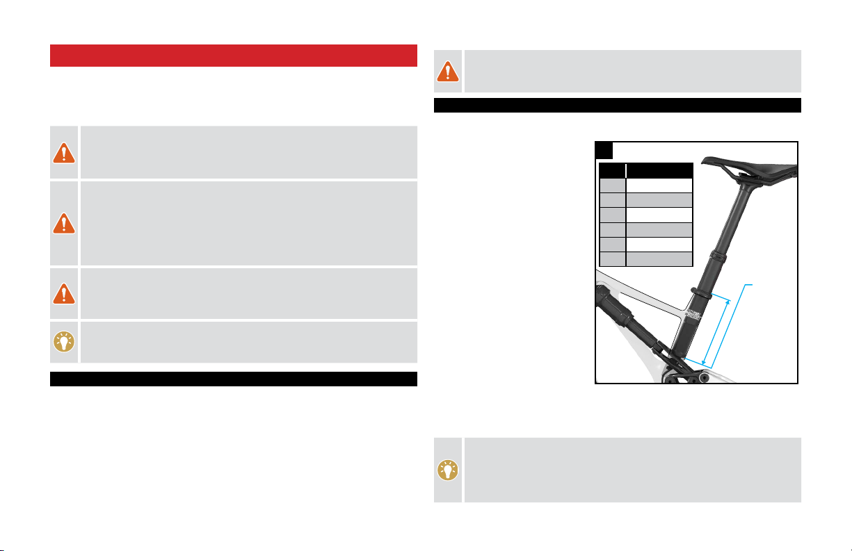
2.2. SEATPOST
SEATPOST MINIMUM INSERTION:
Both the frame and seatpost have
minimum insertion requirements. In
addition, the frame has a maximum
insertion requirement to prevent damage
to the frame and seatpost.
MINIMUM INSERTION: The seatpost
must be inserted into the frame deep
enough so the minimum insertion/
maximum extension (min/max) mark
on the seatpost is not visible. The
frame requires a minimum of 80 mm
of insertion.
MAXIMUM INSERTION: The
seat tube is reamed to a specified
maximum insertion depth for each
frame size. This ream depth limits
the insertion depth of the seatpost.
Please refer to the table in Fig.2.1.
If the desired seat height cannot be achieved within the minimum and maximum insertion
requirements, the seatpost should be replaced for a shorter or longer one.
Once the saddle height is determined, torque the seatpost collar bolt to 55 in-lbf (6.2 Nm).
Do not apply grease to the contact surfaces between the seatpost and the
seat tube. Grease reduces the friction, which is critical to proper seatpost grip.
Specialized recommends the application of carbon assembly compound (fiber
paste), which can increase friction between carbon surfaces. Please visit your
Specialized Authorized Retailer for additional information.
max
2.1
SIZE MAX INSERTION
S1 220
S2 220
S3 240
S4 260
S5 280
S6 300
3
The specified ream depths are listed in the table in Fig. 2.1. The tolerance of
the ream depth can vary from frame to frame. Install a regular 34.9 seatpost
in the seat tube to verify the actual ream depth of the frame.
The seat tube is designed for a 34.9 post but a 30.9 seatpost can be used
with a shim.
WARNING! Failure to follow the seatpost and frame insertion requirements
(Fig. 2.1) may result in damage to the frame and/or seatpost, which could
cause you to lose control and fall.
If the seatpost is cut short, the min/max mark on the seatpost may no longer
be accurate. Before cutting the seatpost, note the min/max depth required by
the seatpost manufacturer.
WARNING! For general instructions regarding the installation of the seatpost,
refer to the appropriate section in the Owner’s Manual. Riding with an
improperly tightened seatpost can allow the saddle and seatpost to slide down,
which can damage the frame and cause you to lose control and fall.
WARNING! Inspect the seatpost and seat tube to ensure that there are no burrs
or sharp edges. Remove any burrs or sharp edges using fine grit sandpaper.
2.3. BOTTOM BRACKET
Stumpjumper EVO models have a threaded 73mm width bottom bracket shell and is compatible
with any BSA threaded outboard bearing bottom bracket. Please refer to the crank manufacturer
documentation for bottom bracket compatibility.
2.4. REAR AXLE
Stumpjumper EVO models are equipped with 148mm Boost rear hub spacing and require a
148mm Boost compatible rear wheel.
The Stumpjumper EVO frame uses the SRAM UDH (Universal Derailleur Hanger) at the rear dropout.
This hanger must be installed following SRAM’s installation instructions. Please refer to the installation
steps on page 28, or refer to the SRAM UDH User Manual.
2.5. SEATSTAY
Stumpjumper EVO models S1 - S4 are equipped with shorter seatstays. The different length
seatstays are for a balanced weight distribution on the front/rear wheels which keeps the
handling characteristics consistent across sizes.
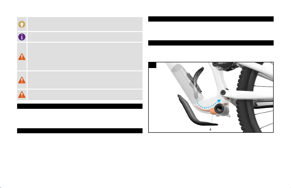
2.6. BULKHEAD AND DOWNTUBE PROTECTOR
The bike is equipped with a downtube protector to protect against cosmetic damage from
minor impacts such as rock strikes. The protector is attached through the frame to an
internally mounted bulkhead.
2.2
Fig. 2.2
The bulkhead is located behind the bottom bracket and slides down into position through the
swat door.
The bulkhead is designed with a locating boss molded into the part and locates into a
corresponding cavity molded into the frame. The boss ensures correct and easy alignment
when inserting the bulkhead into the frame. You can fine adjust the position of the bulkhead
through the SWAT door to align the screw holes.
4
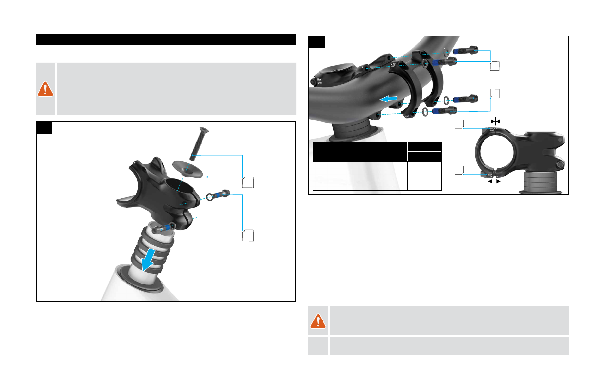
2.7. STEM
The Stumpjumper Evo Comp and Expert models are equipped with an Alloy Trail Stem.
WARNING! The stem is designed with no gap between the stem body and the
faceplate at the upper bolt area. The upper bolts must be tightened such that the
faceplate bottoms out against the stem body before being torqued. Failure to
bottom out the faceplate against the stem body can result in structural damage to
the handlebar.
A
B
2.3
Fig. 2.3
Install the stem on the steerer tube, followed by the top cap and bolt (A), then tighten the
top cap bolt.
Align the stem with the front wheel and torque the rear stem bolts (B) to specification.
NO GAP
GAP
C
D
C
D
LOCATION DESCRIPTION TORQUE
in-lbf Nm
BSteerer Bolts 71 8
C / D Faceplate Bolts 53 6
2.4
Fig. 2.4
Loosely thread the stem bolts through the faceplate and into the stem body.
Position the handlebar to the desired position.
Gradually torque the upper bolts to spec alternating from the left to right bolt to evenly
increase the torque until the spec is reached (C).
Gradually torque the lower bolts, alternating from the left to right bolt to evenly increase the
torque until the spec is reached (D).
Check the handlebar is installed correctly by rotating the handlebars up and down, then
twisting the handlebars side to side while holding the front wheel. If there is any movement
the stem is not sufficiently tightened and should be re-torqued.
WARNING! Burrs and sharp edges can damage the carbon and alloy surfaces
of the components. Any deep scratches or gouges in the stem or fork can
weaken the components.
CAUTION: All edges of the stem in contact with the steerer tube should be
rounded out to eliminate any stress points.

5
hose can penetrate bearing seals and crank interfaces, increasing bearing and crank wear.
Use a clean, damp cloth and bicycle cleaning agents for cleaning.
Do not expose the bicycle to prolonged direct sunlight or excessive heat, such as inside a
car parked in the sun or near a heat source such as a radiator.
WARNING! Failure to follow the instructions in this section may result in
damage to the components on your bicycle and will void your warranty, but,
most importantly, may result in serious personal injury or death. If your bicycle
exhibits any signs of damage, do not use it and immediately bring it to your
Authorized Specialized Retailer for inspection.
WARNING! When placing the frame and/or bicycle in a repair stand, clamp
the stand to the seatpost and not the frame. Clamping the frame can cause
damage to the frame that may or may not be visible, and you may lose control
and fall.
3. GENERAL NOTES ABOUT MAINTENANCE
The Stumpjumper EVO is a high performance bicycle. All regular maintenance,
troubleshooting, repair and parts replacement must be performed by an Authorized
Specialized Retailer. For general information regarding maintenance of your bicycle, please
refer to the Owner’s Manual. In addition, routinely perform a mechanical safety check before
each ride, as described in the Owner’s Manual.
Great care should be taken to not damage carbon fiber or composite material. Any damage
may result in a loss of structural integrity, which may result in a catastrophic failure. This
damage may or may not be visible in inspection. Before each ride, and after any crash,
you should carefully inspect your bicycle for any fraying, gouging, scratches through the
paint, chipping, bending, or any other signs of damage. Do not ride if your bicycle shows
any of these signs. After any crash, and before you ride any further, take your bicycle to an
Authorized Specialized Retailer for a complete inspection.
While riding, listen for any creaks, as a creak can be a sign of a problem with one or more
components. Periodically examine all surfaces in bright sunlight to check for any small
hairline cracks or fatigue at stress points, such as welds, seams, holes, and points of
contact with other parts. If you hear any creaks, see signs of excessive wear, discover any
cracks, no matter how small, or any damage to the bicycle, immediately stop riding the
bicycle and have it inspected by your Authorized Specialized Retailer.
Lifespan and the type and frequency of maintenance depends on many factors, such as
use, rider weight, riding conditions and/or impacts. Exposure to harsh elements, especially
salty air (such as riding near the ocean or in the winter), can result in galvanic corrosion of
components such as the crank spindle and bolts, which can accelerate wear and shorten
the lifespan. Dirt can also accelerate wear of surfaces and bearings. The surfaces of the
bicycle should be cleaned before each ride. The bicycle should also be maintained regularly
by an Authorized Specialized Retailer, which means it should be cleaned, inspected for
signs of corrosion and/or cracks and lubricated. If you notice any signs of corrosion or
cracking on the frame or any component, the affected item must be replaced.
Regularly clean and lubricate the drivetrain according to the drivetrain manufacturer’s
instructions.
Do not use a high pressure water spray directly on the bearings. Even water from a garden

6
FRAME SIZE S1 S2 S3 S4 S5 S6
A STACK (MM) 613.2 617 626 635 644 654
B REACH (MM) 408.1 428 448 475 498 528
C HEADTUBE LENGTH (MM) 95 95 105 115 125 135
D HEADTUBE ANGLE ( °) 64.3 °
EBB HEIGHT (MM) 335 340 340 340 340 340
F BB DROP (MM) 40 35 35 35 35 35
GTRAIL (MM) 131
H FORK LENGTH (FULL) (MM) 561 571 571 571 571 571
IFORK RAKE/OFFSET ( MM) 44
J FRONT CENTER (MM) 734 758 782 809 838 875
K CHAINSTAY LENGTH (MM) 438 438 438 438 448 448
L WHEELBASE (MM) 1169 1193 1218 1249 1287 1321
M BIKE STAND-OVER HEIGHT (MM) 733 764 763 762 767 789
N SEAT TUBE LENGTH (MM) 385 385 405 425 445 465
O SEAT TUBE ANGLE ( °) 78 ° 77.6 ° 77.2 ° 76.9 ° 77 ° 77 °
P TOP-TUBE LENGTH (HORIZONTAL) (MM) 538 564 590 623 647 679
CRANK LENGTH (MM) 165 170 170 170 170 175
HANDLEBAR WIDTH (MM) 800
STEM LENGTH (MM) 40 40 50 50 50 50
SADDLE WIDTH (MM) 155 155 143 143 143 143
SEATPOST MAX INSERTION (MM) 220 220 240 260 280 300
SEATPOST MIN INSERTION (MM) 80 80 80 80 80 80
REAR WHEEL WIDTH (MM) 148 mm
FORK SIZE (MM) 150 160 160 160 160 160
The above table shows the standard geometry for the bikes as shipped. Visit www.specialized.
com for all possible geometry configurations.
4. SPECIFICATIONS
4.1. GEOMETRY
A
B
C
D
O
E
F
G
H
I
J
K
L
M
N
7
4.2. GENERAL SPECIFICATIONS
ITEM PART # SPECIFICATION
HEADSET S182500005
HDS NO.42/ACB/S/F/N 46CONE SPACER,AL COMPRS
RING,UP1.125/LOW1.5 CRMO 45,AL CROWN RACE,ANO MATT
BLK
HEADSET CUPS S202500010 HDS MY21 SJ EVO CARBON HEADSET CUP
SEAT COLLAR S184700004 STC KCNC, SPL-SC02-386, EXTRUDED, 7075-T6, 38.6MM,
SCM435, NONE FINISH BOLT, BOLT CLAMP TYPE
SEAT COLLAR DIAMETER 38.6mm
SEATPOST DIAMETER 34.9mm
DERAILLEUR HANGER S202600002
HGR SRAM AC UDH DERAILLEUR HANGER AL BLACK
(00.7918.089.000)
BOTTOM BRACKET SHELL BSA THREADED 73mm
CHAINGUIDE TABS ISCG-05
REAR HUB AXLE S170200003 AXL THROUGH AXLE, JD JD-QR43, 7075-T73 AXLE W/C6801
WASHER, REAR, 148MM SPACING, 172MM LENGTH, 12MM
REAR TIRE MAX 29 x 2.5”
*REAR TIRE WITH 27.5 LINK 27.5 x 2.5
REAR WHEEL TRAVEL S1=145, S2-S6=150
SHOCK LENGTH / STROKE 210mm / 50mm (S1), 55mm (S2-S6)
SHOCK SAG 16.5mm (30%)
SHOCK EYELET 8mm ID x 20mm W
MAX FORK TRAVEL 150mm (S1), 160mm (S2-S6)
MIN / MAX CHAINRING 28 - 34t
MIN / MAX REAR BRAKE ROTOR 180 mm / 220 mm
* By switching the rear shock link for a separately available modified link it is possible to fit a
27.5" rear tire to the Stumpjumper EVO and maintain the geometry. This link (S204300005)
is available from your Authorized Specialized Retailer.
WARNING! Only single crown forks with a specified amount of travel or range
of travel should be used . Use of different styled forks or forks with longer
travel may result in catastrophic failure of the frame which may result in
serious personal injury or death.
WARNING! While the SJ EVO frame is generally compatible with tires up
to 29 x 2.5, tire dimensions can vary depending on the manufacturer, and
not all forks are designed to accept a larger tire. Always check with the fork
manufacturer regarding required clearances.
CAUTION: Certain chainrings may not have adequate clearance with the
chainstay. Verify spacing and chainline before using it.
4.3. SHOCK CUSTOMIZATION
Specialized frames are generally designed and tested to work with the suspension
components provided as original equipment. When changing out shocks, be aware certain
models of shocks may not be compatible with the frame due to the position of the shock
reservoir, size, and/or other compatibility factors, even if they fit. Always check with your
Authorized Specialized Retailer for advice on compatible shocks.
WARNING! Use of an incompatible shock may cause damage to the shock or
the frame and can cause you to lose control and fall.
4.4. TOOLS REQUIRED
3, 4, 5, 6, 8 mm ALLEN (HEX) KEYS BLUE THREAD-LOCKER (LOCTITE 243)
TORQUE WRENCH (reversible type, for SRAM UDH) GREEN RETAINING COMPOUND (LOCTITE 603)
HIGH PRESSURE SHOCK PUMP CABLE AND HOUSING CUTTERS
HIGH QUALITY GREASE TORX T10 DRIVER
4.5. BOLT SIZE / TOOLS / TO TORQUE SPECIFICATIONS
WARNING! Correct tightening force on fasteners (nuts, bolts, screws) on your
bicycle is important for your safety. If too little force is applied, the fastener
may not hold securely. If too much force is applied, the fastener can strip
threads, stretch, deform or break. Either way, incorrect tightening force can
result in component failure, which can cause you to lose control and fall.
Where indicated, ensure that each bolt is torqued to specification. After your
first ride, and consistently thereafter, recheck the tightness of each bolt to
ensure secure attachment of the components. The following is a summary of
torque specifications in this manual:

8
4.6. GENERAL TORQUE SPECIFICATIONS
LOCATION TOOL TORQUE
(in-lbf) (Nm)
SEAT COLLAR 4mm HEX 55 6.2
12MM REAR AXLE 6mm HEX 133 15.0
DERAILLEUR HANGER 8mm HEX 221 25.0
WATER BOTTLE BOSS 3mm HEX 25 2.8
SWAT LATCH T10 TORX 0.53 30.1 3
3CAUTION: Tighten SWAT latch screws intermittently until there is no more
wiggle of the latch, then turn each screw another 1/4 turn
4.7. BEARING SPECIFICATIONS
QTY PIVOT LOCATION
DIMENSION
BEARING
A2 MAIN PIVOT (CHAINSTAY) 15 ID x 24 OD x 7 W DOUBLE ROW 6901V-2RS
B6 LINK
12 ID x 21 OD x 5 W 6800V-2RS
C4 HORST
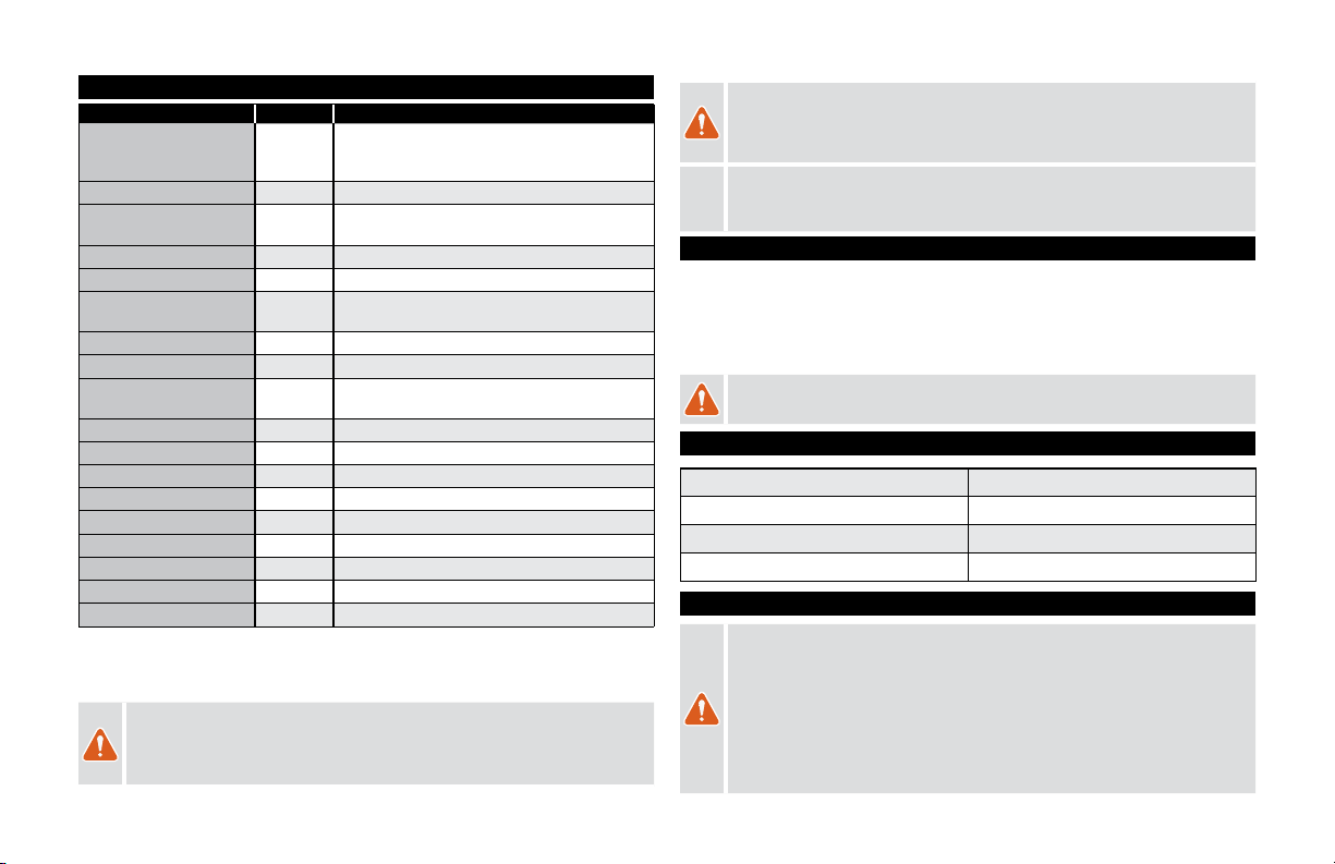
4.8. SPACER/AXLE/BOLT SPECIFICATIONS
QTY LOCATION / ITEM
DIMENSIONS
TOOL
TORQUE
in-lbf Nm
D2 HORST PIVOT BOLT SCR,CUST,M6X1.0 X
32.5,STL,BLK 5 mm HEX 90 10
E2HORST PIVOT ADJUSTABLE
SPACER OUTSIDE
DO PIVOT SPACER,GEO
ADJ,6.0 ID, FLAT
F2HORST PIVOT ADJUSTABLE
SPACER INSIDE
DO PIVOT SPACER,GEO
ADJ,M6 x 1
G4 HORST PIVOT OUTER SPACER HORST PIVOT OUTER
SPACER ASSY 12X21X2.5
H2 HORST PIVOT CENTER SPACER SPCR,STEP,6MM ID X 16MM
OD X 16MM W,7075-T6
I2 MAIN PIVOT SPACER SPCR,15.1 ID X 21.5 OD X 2.5
W,FSR,AL7075
J1 MAIN PIVOT BOLT DS SCR ASSY,CUST,OD15 X
,M14x1,7075,LH,BLK 6 mm HEX 210 24
K1 MAIN PIVOT BOLT NDS SCR ASSY,CUST,OD15 X
,M14x1,7075,BLK 6 mm HEX 210 24
L2 LINK @ SEAT STAY BOLT SCR,CUST,M6X1.0 X 8,SST
302 4 mm HEX 60 7
M2 LINK @ SEAT STAY AXLE BOLT,CUST,M6 X1FEM X
22.34,7075,BLK 6 mm HEX 60 7
N4 LINK @ SEAT STAY SPACER SPCR,CUST, 10 ID X 18.5 OD
X 2.5 W,FSR,AL7075-T73
O4 LINK @ EXTENSION SPACER SPCR,CUST, 10 ID X 18.5 OD
X 2.5 W,FSR,AL7075-T73
P2 LINK @ EXTENSION BOLT SCR,CUST,M6X1.0 X 8,SST
302 4 mm HEX 60 7
Q2 LINK @ EXTENSION AXLE AXLE,SS PIVOT,MTB,TRAIL
FSR L1 5 mm HEX 60 7
R2 LINK @ SEAT TUBE BOLT SCR ASSY,M12 X 1.0 X
17,21MM HEAD,FSR 6 mm HEX 180 20
S2 LINK @ SEAT TUBE SPACER SPCR,12.1 ID X 19.5 OD X 3
W,FSR,AL7075-T6
T1 FORWARD SHOCK EYE BOLT SCR,CUST,M8X1.0 X
42,CHROMOLY 6 mm HEX 90 10
U1 REAR SHOCK EYE BOLT SCR,CUST,M8X1.25 X
27,CHOMOLY
6 mm LR
HEX 180 20
V1 REAR SHOCK EYE WASHER WSHR,FLAT,M8,8.2 ID X 13
OD X 0.5 THK,304 SST
W2REAR SHOCK EYE TOP HAT
SPACER
SPACER,SHOCK,19X8.1X0.6,SST
304

9
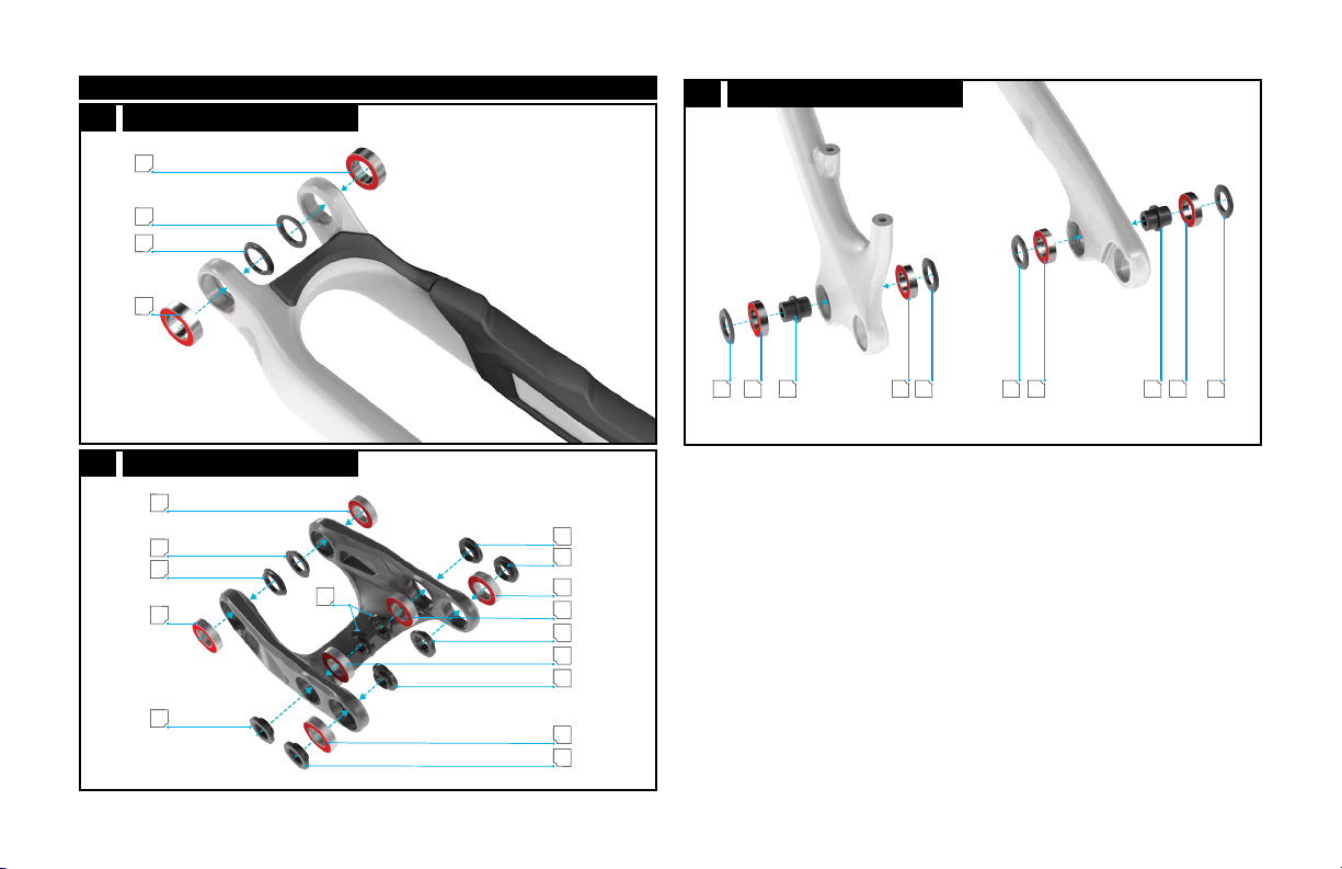
NO
S S O B NO
B B
A I AI
O N B N B
G C C GH G C H C G
B
4.1 EXPLODED VIEW - BEARINGS/SPACERS
10
RT W Q M L Q M
V
W
URP
J K
D E F F E D
4.2 EXPLODED VIEW - BOLTS

11
Fig. 5.1
Route the seatpost housing into the drive side ICR port near the head tube. From the SWAT
opening, guide the housing into the molded channel (located under the SWAT Latch) then
down to the bottom bracket area and up the seat tube.
Once the housing is going up the seat tube, it may want to go up the side-arm instead of
up the seat tube. If this happens, cut a long, narrow strip of card stock paper or use a long,
thin ruler to slide down the seat tube and block access to the side-arm.
Once the housing exits the top of the seat tube, install the seatpost according to the
manufacturer’s instructions.
5.2. INTERNAL GUIDE TUBES
Before you start:
The head-tube cable guide should be removed from the frame.
The rear shock, extension, and link should be fully installed in the frame.
The bottom bracket port and mudflap should be installed on the front triangle.
The chainstay should be separated from the frame assembly.
INFO: Install a shift housing into each ICR tube before routing them through the
frame. This prevents kinking of the nylon tube and makes insertion easier.
5. INTERNAL ROUTING
The ICR tubes must be installed without the fork installed in the frame.
5.1. DROPPER SEATPOST
To simplify assembly, always install the seatpost housing before the shift and
brake housings.
5.1

12
NYLON ICR TUBE
5.3
Fig. 5.3
Carefully guide each tube parallel to each other (DON'T CROSS THE TUBES) into the front
triangle, up the side-arm, and out the drive-side head-tube port.
Make sure the ICR tubes go into their respective sides (left nylon tube in the left porthole).
TECH TIP: It helps if the tubes are arcing down when entering the front
triangle so that they automatically find their way into the side-arm.
Carefully assemble the main pivot, making sure all parts assemble freely and precisely.
50
mm
50
mm
MARK
CABLE
5.2
Fig. 5.2
Mark the brake ICR tube before insertion, this will indicate which tube will be used for the rear
brake after routing.
Take the marked rear brake ICR tube and route it from front-to-back into the chain-stay via the
non-drive-side hole near the main-pivot.
Guide the ICR tube out of the rearward ICR port in the chain-stay with a 4 - 5 mm round punch
and leave about 50 mm of the tube exposed.
Repeat the process for the rear derailleur ICR tube.
TECH TIP: Glue a piece of tubing onto a 5.2 - 5.4mm straight-punch and taper
the end so that it guides the tube out of the chain-stay flawlessly. It makes
assembly MUCH easier.
Connect the seat-stay to the link, then connect the chain-stay to the seat-stay. See section
4.4 for the complete assembly process.
13
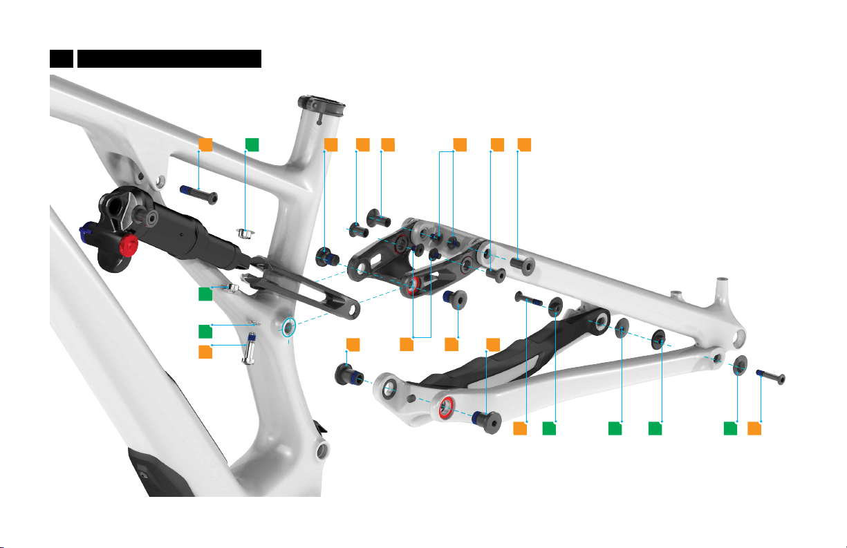
75%
100%
30
SEC
CROSS SECTION VIEW
<
5.5
Fig. 5.5
Install the head-tube cable guide to the ICR tubes so that they are 75% inserted.
Add a small drop of glue (Loctite 416) to each tube. Briefly allow the glue to spread around
the tube then quickly insert them completely into the guide.
TECH TIP: Loctite 416 has a 20-30 second work time.
INFO: Make sure the tubes are completely inserted into the head-tube ICR
port, failure to do so will cause housings to snag.
5.4
Fig. 5.4
Pull the ICR tube from chainstay end or trim each ICR tube at the head-tube port so that
there is about 70mm protruding from the frame.

14
2 MM
3 MM
5.6
Fig. 5.6
Install the M3 set-screw into the head-tube cable guide until it sits flush with the face of the
guide.
Once more, gently pull each ICR tube out the chainstay while guiding the head-tube cable
guide into place.
Install the fastening screw and torque to spec.
5.7
Fig 5.7
Grab the shift housing that's still in the tubes on both ends and give the ICR tubes a gentle
pull to set them in place inside the frame.
INFO: Only pull on the housing, DO NOT pull on the ICR tube.
TECH TIP: When gently pulling the tubes out from the chainstay ports, be
sure to not pull the tubes from the head tube port. Only pull enough to find its
natural curvature position within the frame.
15
5.3. SHIFT/BRAKE HOUSING
REAR BRAKE:
Starting at the exit port on the inside surface of the non-drive side of the chainstay, route
the housing through the internal guide tube from the chainstay until it exits the frame on the
non-drive side of the head tube port.
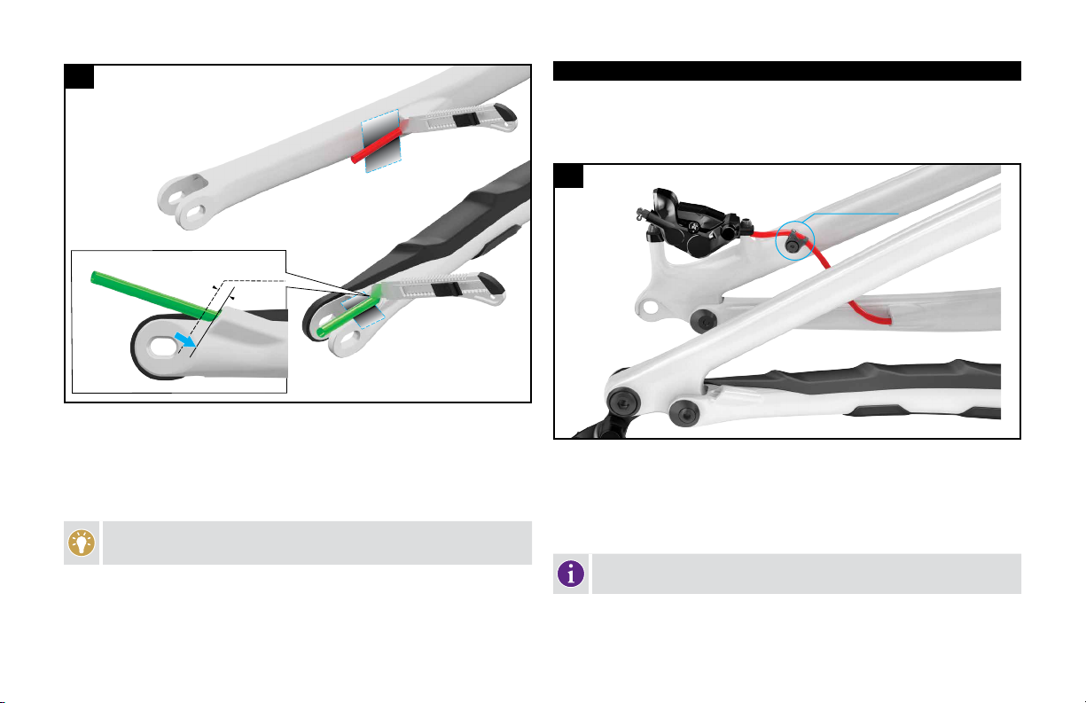
USE CLIP WITH
OUTSIDE BANJO ONLY
5.9
Fig. 5.9
OUTSIDE BANJO CALIPERS: Position the seatstay brake housing clip so that it is
perpendicular to the tube and the housing is above/in front of the bolt. Ensure that the
housing has a natural loop (curvature) between the seatstay and chainstay.
Finish the brake assembly installation according to the manufacturer’s instructions.
INFO: Always make sure that there is enough slack in the brake line so that it
does not pull tight during suspension actuation.
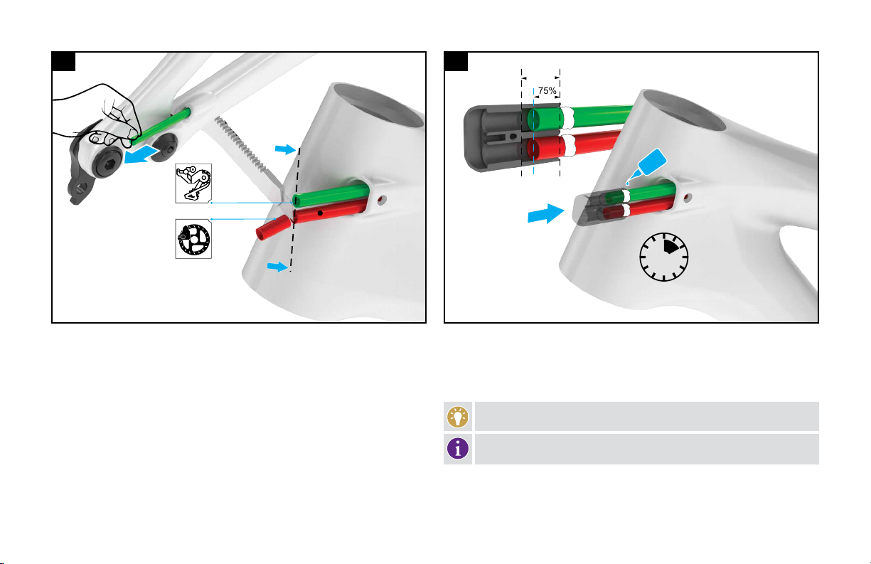
5mm
CUT
5.8
Fig. 5.8
Trim the excess guide tubes at the chainstay exit ports.
Use a new/sharp heavy-duty cutting blade to trim about 5 mm past the edge of the exit
port. Match the cut angle with the guide port exit angles.
Push the exposed ICR tube back into the frame so that it is flush.
TECH TIP: Place a protective strip between the chainstay and the tube, so the
razor blade doesn’t damage the finish of the frame.

16
REAR DERAILLEUR (Mechanical):
Starting at the exit port in front of and below the drive side dropout, route the housing through
the internal ICR tube through the chainstay until it exits the head tube on the non-drive side.
Finish the shift assembly installation according to the manufacturer’s instructions.
5.4. HEAD TUBE ICR PORT
DRIVE SIDE NON-DRIVE SIDE
A
B
C
D
5.10
Fig. 5.10
Route the shift cable through the upper port (A) and the brake housing through the lower port (B).
Use the rubber plug (D) to close the upper exit hole on the ICR port (A) on the non-drive
side if you’re running wireless shifting.
Use the rubber plug (D) to close the exit hole on the drive side exit port (C) if you’re running
a wireless actuated dropper post and not running a cable-actuated dropper post.
6. REAR TRIANGLE PIVOT ASSEMBLY
To successfully build the Stumpjumper EVO rear triangle, it is very important
to follow the order of operations as outlined in this manual. Modifying the
order of assembly will result in a longer build process.
To properly assemble the Stumpjumper. Grease all surfaces that contact inner
bearing races before placing the spacers against the bearings. This helps keep the
spacers in place when assembling each pivot. Always place the smaller (tapered)
surface against the bearing, and the wider surface against the frame or stay.
All pivot bolts are factory treated with a blue thread locker patch to help
prevent the threads from seizing and/or creaking. Additionally, grease can be
applied to the entire contact surface of the bolts.
Apply green retaining compound (Loctite 603) to all the bearing/bore
interface surfaces, then press all the bearings into their respective pivot
locations.
Install the bottom bracket after the rear triangle is assembled.
17
GCHCGGCHCG
6.3 HORST BEARINGS AND SPACERS
Fig. 6.3
Place the spacer into the bearing hole from the outer side of the chainstays.
Insert the bearings from both sides of the chainstay, sandwiching the spacer in the center.
6.1. BEARING ASSEMBLY
A
I
I
A
6.1 MAIN PIVOT BEARINGS AND SPACERS
O
N
B
B
N
N
B
B
N
S
B
S
B
O
O
6.2 LINK BEARINGS AND SPACERS
This manual suits for next models
6
Table of contents
Other StumpJumper Bicycle manuals


