ProActiv SPIKE Adaptive bike Troubleshooting guide

Operating instructions SPIKE adaptive bike
0
MOBILITY MADE SIMPLE!
Operating instructions
Service booklet
SPIKE Adaptive bike

Operating instructions SPIKE adaptive bike
1
Contents
1Preface............................................................................................................................................... 3
2Legend................................................................................................................................................ 3
3CE Declaration of Conformity / other information............................................................................... 3
3.1Classification............................................................................................................................... 3
3.2Declaration of Conformity........................................................................................................... 3
3.3Manufacturer............................................................................................................................... 3
4Scope of delivery................................................................................................................................ 3
5Introduction......................................................................................................................................... 4
6Product description / purpose............................................................................................................. 4
7Acceptable usage and operating conditions / places of use.............................................................. 4
8Technical specifications ..................................................................................................................... 5
8.1Product weight............................................................................................................................ 5
8.2Load weight ................................................................................................................................ 5
8.3Obstacle height and turning circle.............................................................................................. 5
8.4Basic equipment & dimensions .................................................................................................. 5
8.5Service life .................................................................................................................................. 5
9Rating plate ........................................................................................................................................ 6
10Commissioning................................................................................................................................... 6
11Hand-over........................................................................................................................................... 6
12Safety instructions – prior to driving / use......................................................................................... 7
13Safety instructions – while driving / using .......................................................................................... 7
14Safety instructions regarding obstacles ............................................................................................. 9
15Safety instructions regarding dangerous locations and dangerous situations................................... 9
16Adapter & adaptation........................................................................................................................ 10
17Functional elements......................................................................................................................... 10
17.1Parking stand............................................................................................................................ 10
17.1.1Active and passive positions........................................................................................ 10
17.1.2Parking stand height adjustment......................................................................... 10
17.2Pedal bearing support & crank......................................................................................... 11
17.2.1Seating position ........................................................................................................... 11
17.2.2Pedal bearing position ................................................................................................. 12
17.2.3Crank length and grip width......................................................................................... 13
17.3Grips ......................................................................................................................................... 13
17.4Gear shift .................................................................................................................................. 14
17.4.1Hub gears .................................................................................................................... 14

Operating instructions SPIKE adaptive bike
2
17.4.2Pedal bearing gearshift................................................................................................ 14
17.5Brake......................................................................................................................................... 15
17.5.1Rim brake.....................................................................................................................15
17.5.2Back-pedal brake for hub drives.................................................................................. 15
17.5.3Parking brake............................................................................................................... 15
17.6Components ............................................................................................................................. 16
18Storage............................................................................................................................................. 16
19Transport.......................................................................................................................................... 16
20Malfunctions ..................................................................................................................................... 17
21Cleaning and care ............................................................................................................................ 17
22Maintenance..................................................................................................................................... 17
22.1General instructions.................................................................................................................. 17
22.2Service schedules..................................................................................................................... 18
22.3Proof of maintenance................................................................................................................ 18
23Disposal & Recycling........................................................................................................................ 18
24Re-use.............................................................................................................................................. 19
25Warranty........................................................................................................................................... 19
26Liability.............................................................................................................................................. 19
27Appendix: Tightening torques and securing details ......................................................................... 20
28Appendix: Medical product passport / record of training.................................................................. 21
29Appendix: Hand-over certificate....................................................................................................... 22
29.1Required compliance criteria to authorise use .........................................................................22
29.2Check list for training the user.................................................................................................. 23
30Appendix: Inspection lists................................................................................................................. 24

Operating instructions SPIKE adaptive bike
3
1 Preface
Dear Customer,
Congratulations on purchasing your new
PRO ACTIV product. You have bought a
quality product which has been especially
customised to meet your requirements.
We have put together some instructions about
its proper and safe use in the following
document. Please read these instructions
before using the product.
Throughout these operating instructions, the
operation of standard components is
explained. If you have individual solutions or
non-standard components on your product,
your dealer or we at PRO ACTIV would be
happy to deal with any questions you may
have about handling it.
If you have any further questions about this or
any of our other products, we would be glad to
be at your disposal.
Enjoy your trips and the best possible mobility.
Your PRO ACTIV team
2 Legend
The symbols used in these operating
instructions have the following meanings:
Manufacturer
Warnings and safety instructions
Serial number
Additional information
Assembly instructions for the dealer (see
table of contents)
3 CE Declaration of Conformity /
other information
3.1 Classification
The SPIKE adaptive bike (referred to as a
"product" below) is classified as a class I
product.
3.2 Declaration of Conformity
PRO ACTIV Reha-Technik GmbH declares in
the context of an individual declaration of
conformity that the respective product has
been developed and manufactured according
to the relevant provisions of
EC Directive 93/42/EEC 2007.
If the product is adapted in a manner which
has not been agreed by PRO ACTIV Reha-
Technik GmbH, this declaration becomes void.
3.3 Manufacturer
PRO ACTIV Reha-Technik GmbH
Im Hofstätt 11
D-72359 Dotternhausen
Tel. +49 7427 9480-0
Fax +49 7427 9480-7025
E-Mail: info@proactiv-gmbh.de
Web: www.proactiv-gmbh.com
4 Scope of delivery
The product may only be operated with an
adapter supplied by PRO ACTIV which is
suitable for the wheelchair.
The delivery includes the product configured in
accordance with the order, with operating
instructions including record of training / hand-
over certificate and inspection lists. You can
view the basic equipment in chapter "Technical
specifications". As per your order, the product
is equipped with additional recommended
accessories, such as e.g., lighting and clip-on
fender.
Please check that the delivery is complete after
you have received your product.
The product is tested to ensure it is completely
functional prior to shipping. If your product has
been damaged during transit, please contact
your dealer or PRO ACTIV immediately.

Operating instructions SPIKE adaptive bike
4
5 Introduction
Before starting your journey for the first
time, familiarise yourself with these operating
instructions paying particular attention to the
safety information and hazard warnings
contained within them.
If you are not sure how to handle the
product or if technical faults occur, please
contact your dealer or PRO ACTIV before
using it.
When operating the product, the
wheelchair operating instructions must also be
observed. Information on limit values must not
be exceeded. If the values contained in the two
operating instructions differ, the lower limit is
the one which applies.
Never leave the product unattended.
6 Product description / purpose
The product is attached to a manual
wheelchair as a mechanically propelled drive
unit which supports the wheelchair user in
being mobile. It is easier to cover longer
distances with ergonomic movement
processes using one's own wheelchair. This
expands the activity radius. Through the
product's larger drive wheel (compared with
the caster wheels of the wheelchair) and the
wheelchair's steering wheels which are raised
from the ground uneven routes and barriers
can overcome more easily and without danger.
The downhill speed can be regulated via the
product's braking systems, so that downhill
slopes can be travelled on safely.
For safety reasons, the product may only be
operated by persons who
have been trained in its use by the dealer
or PRO ACTIV.
can move and control their hands and
arms so that they are able to operate the
controls and perform the full steering
movement without restrictions while
driving.
are physically and mentally capable of
safely operating the device in all operating
situations and can meet the legal
requirements for use on public roads.
7 Acceptable usage and operating
conditions / places of use
Observe the instructions on permitted
operating conditions in the operating
instructions for your wheelchair which the
product has been adapted to.
Use the product on paved surfaces. Avoid
driving on unpaved or loose surfaces (e.g. on
loose gravel, in sand, mud, snow, ice or
through deep puddles of water), as this may
result in incalculable risks.
The wheelchair with the adapted product must
be equipped in accordance with road traffic
regulations when operated on public roads and
spaces.
The maximum permitted load of the product in
its standard design is 75 kg towed capacity
and 5 kg payload. Individual customisation can
be made to accommodate a higher load; this
will be indicated on the ratings plate. Please
ensure that the load limit indicated on the
ratings plate is not exceeded when
transporting objects.
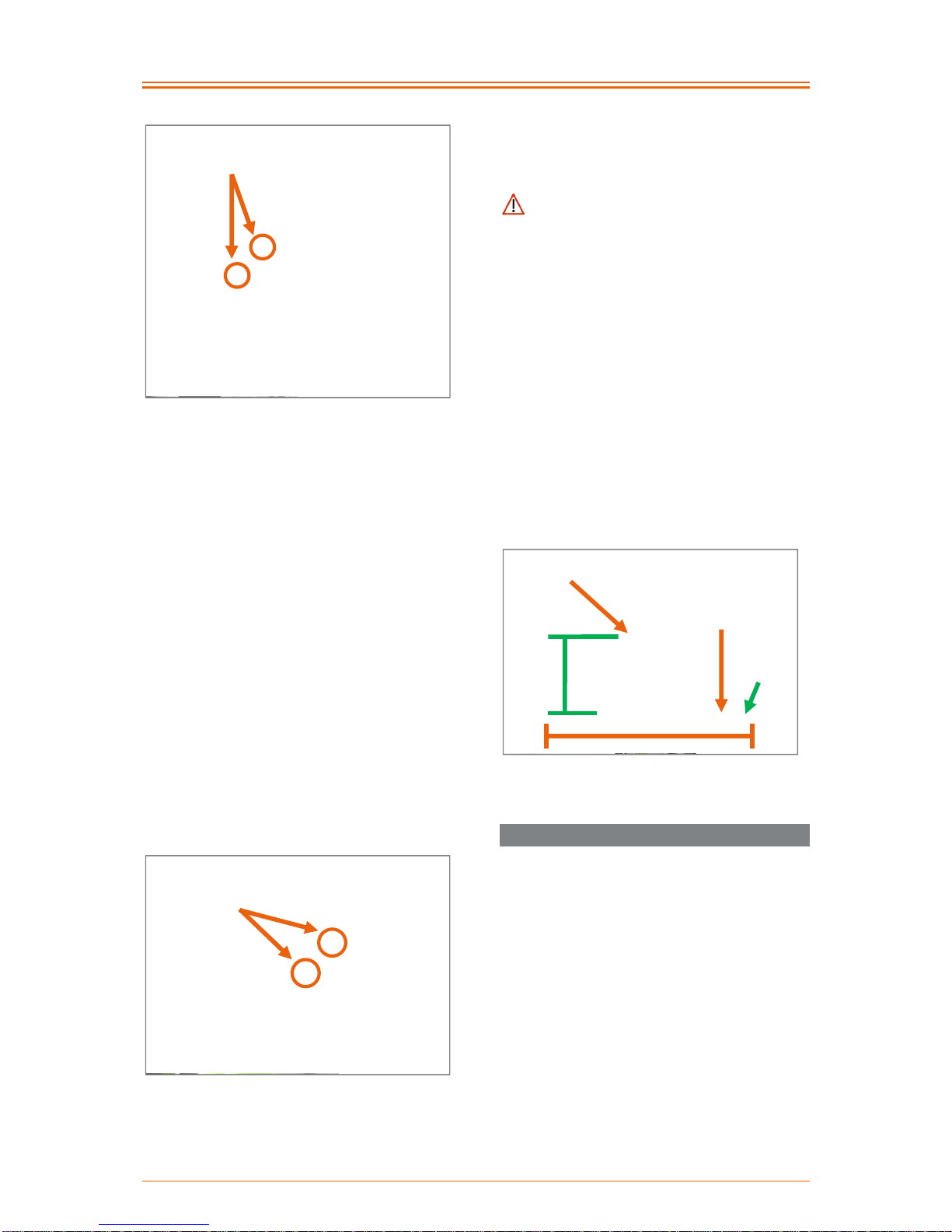
We recommend: The wheelchair can be
equipped with a anti-roll back device and that
this is activated before driving on slopes. The
anti-roll back device can also be used if a
wheelbase extension is used on the
wheelchair.

Operating instructions SPIKE adaptive bike
5
Figure 1: Anti-roll back device
We recommend: The wheelchair should be
equipped with a wheelbase extension. Before
driving with the traction system, the wheelchair
wheels should then be positioned in the
wheelbase extension. This allows a more
optimised distribution of the weight between
the drive wheel of the product and the
wheelchair wheels to be achieved. This
minimises the risk of the product wheel slipping
on slopes.
Figure 2: Removable wheelbase extension
8 Technical specifications
8.1 Product weight
The total weight starts from 7.3 kg with the
basic equipment.
8.2 Load weight
Maximum load weight:
75 kg towing capacity and 5 kg payload
8.3 Obstacle height and turning circle
Maximum drive-over / negotiable obstacle
height: 10 cm (must be ensured through an
appropriate adapter assembly / setting,
steering wheels must be removed
(recommended equipment of the
wheelchair: steering forks with quick-release
axle))
Turning circle:
approx. 3.5 m without manoeuvring back
and forth
approx. 2.3 m with manoeuvring back and
forth (much dependent on the number of
manoeuvres)
8.4 Basic equipment & dimensions
In its basic equipment, the product comprises
one drive unit with docking plate, handles with
brake fittings, chain guard and rim brake.
Dimensions, SPIKE adaptive bike:
Product height: approx. 70-90 cm (depending
on the length of the pedal bearing support)
Product width: approx. 41-50 cm (depending
on the grip width, parking stand in passive
position)
Grip width: 36-45 cm
Crank length: 135-175 cm
8.5 Service life
The service life of the product is 6 years in
accordance with the medical products law.

Operating instructions SPIKE adaptive bike
6
9 Rating plate
The rating plate is located on the pedal
bearing. The rating plate includes the precise
model, the serial number and other technical
specifications.
When contacting your dealer or PRO ACTIV
with regard to your product, please always
have the serial number and year of
construction on the rating plate at hand.
The rating plate includes the following data:
Manufacturer
CE marking
Operating instruction present for the
product
Serial number
10 Commissioning
The product will be handed over to you ready
for use by a PRO ACTIV dealer or a field
representative or by a product consultant from
PRO ACTIV. They will fit, if not already done,
the required fastening elements to your
wheelchair to hold the adapter and, if required,
any other accessories. The height of the
parking stand is also adjusted correctly.
Finally, you will be fully instructed in the use of
the product based on the operating instructions
included in delivery. If you wish (recommended
by PRO ACTIV), you will be presented with a
record of training and a hand-over certificate
as written evidence and in addition the
operating instructions and any other
accessories for your own use. The form for the
record of training and the hand-over certificate
can be found in chapters 28 and 29.
It is recommended that you take along an
assistant to the training so that, if required,
they can assist you later when handling the
product.
During the initial commissioning of the product,
drive at minimum speed and become
accustomed to the driving characteristics of the
product. Always adapt the speed and driving
manoeuvres to match your own abilities, the
external circumstances and the legal
regulations. You will get a feel for how to use
the product safely after a short time. Before
driving up or down slopes or hills with the
product, you should be proficient in the safe
handling of the product on the flat.
11 Hand-over
The hand-over must be done by your dealer or
a field representative or by a product
consultant from PRO ACTIV. During the hand-
over, the record of training (chapter 28) and
the hand-over certificate including the
associated check list (chapter 29) must be
filled in. The dealer should send a copy of the
completed documents to PRO ACTIV for filing
either as a scanned file via e-mail, by fax or in
the post. These documents are available as
pdf files which can be completed in the
download area at www.proactiv-gmbh.com
under the link "more documents >>".

Operating instructions SPIKE adaptive bike
7
12 Safety instructions –
prior to driving / use
The operating instructions of the
connected wheelchair must be strictly
observed when using the product.
If your wheelchair is operated in
combination with the product, any existing anti-
tipping supports must be put into their passive
position or removed (see the wheelchair's
operating instructions). If the wheelchair is then
used without the product, the anti-tipping
supports must be brought back into their
operating position again to ensure tipping
stability.
Before every trip, check the condition of
the wheels (e.g. visual inspection of the spokes
and rims, check the tyres for damage, foreign
bodies and crack formation). If you have any
doubts, the wheelchair-product combination
must not be operated any further. In this case,
contact your dealer or PRO ACTIV.
Check tyre pressures at regular intervals.
Ensure that you comply with the
manufacturer's specifications which can be
found on the tyres. Tyre pressure which is too
low affects handling and has a negative effect
on the braking action for wheelchairs).
Before starting your trip check that the
product's brake functions. If all existing brakes
are not fully functional, no trips may be taken.
Before every trip, check that the product is
firmly attached to the adapter and that the
adapter is firmly attached to the wheelchair.
The product may not be operated on the
wheelchair if any of the connections are not
tight and secure. In this case, contact your
dealer or PRO ACTIV.
Always ensure that your feet cannot slip
off the feet plate of the wheelchair when using
the product, if necessary by using a special
fixation device.
If present, check the function of the front
and rear lights as well as the effectiveness of
the side and rear reflectors before every trip.
Lights and reflectors must be clearly visible
during the journey and must not be covered by
other objects. Especially trips that take place in
the dark or in the twilight, the lighting must be
functional and visible. For longer trips in the
dark, we recommend that you also take along
extra batteries.
To minimise the risk of suffering serious
head injuries in the event of a fall, a helmet
should always be worn when driving with the
product.
When travelling, always carry a repair kit
and tyre pump for repairs in event of
punctured / flat tyre. A alternative to this is a
pump spray that fills your tyre with a foam that
hardens in the tyre.
13 Safety instructions – while
driving / using
Always hold onto the crank handles with
both hands while driving. If the driving situation
requires you to take one hand off the crank
handles, this is only permitted when the speed
has been reduced to the minimum possible
beforehand.
Increase the speed slowly up to the
desired speed.
Use particular caution when approaching
stairs, edges, drops or other hazard areas.
When waiting at potential hazard areas
(e.g. while waiting at a pedestrian crossing, on
hills or slopes or at ramps of any type), always
hold down the service brakes.
When driving round a bend, reduce your
speed to a minimum.
Do not ride parallel to slopes due to the
risk of tipping.

Operating instructions SPIKE adaptive bike
8
You may only drive on slopes where the
wheelchair-product combination can be safely
controlled by steering and braking of the
product.
Due to the increased turning circle, it can
be difficult to turn in buildings, in front of or in
lifts or other buildings, as the standard in such
buildings assumes a maximum turning circle of
1.5 m.
Do not attach objects (carrier bags, etc.)
to the product. These could prevent safe
operation of the product while driving.
When driving on areas which are used for
pedestrians, observe the maximum permitted
speed (walking speed 6 km/h) and keep a
sufficient distance (at least the width of a
wheelchair) from the kerbs or other obstacles
and other road users.
When driving on public roads and
footpaths, the provisions of the road traffic
regulations (German StVO) must be observed.
Avoid driving on unpaved or loose
surfaces (e.g. on loose gravel, in sand, mud,
snow, ice or through deep puddles of water).
When travelling on poorly maintained
paths (e.g., large gravel, potholes) there is an
increased risk of puncturing your tyres as well
as tipping.
If you encounter new driving situations
which are unknown to you, approach them with
great care. If you consider that the risk is too
high, you must immediately abort the driving
manoeuvre and, if required, call for help to
assist you in extracting yourself from this
situation.
You must not make telephone calls while
driving.
Operating the product can affect other
devices, for example theft protection barriers in
department stores.
By performing regular checks, ensure that
the safety bolts of the adapter are always in
the correct position while driving (see operating
instructions "Adapter & adaptation").
When driving, never jerk the handlebars to
the left or the right, as this may cause the
wheelchair-product combination to tip over
sideways in certain circumstances.
While driving, never grab onto the
wheelchair wheels, in the area of the product
wheel, in the area of the chain / sprockets /
chain wheels or into other rotating parts; if you
do you may cause injuries.
Only brake the product using the service
brakes.
During long trips the brakes of the product
may heat up. Therefore, do not touch the
brakes during or immediately after the trip (e.g.
when detaching or loading the product).
If the situation allows it, the speed should
be reduced by carefully applying the service
brake. Abrupt braking can cause the upper
body to fall forwards which can thereby result
in injuries or loss of vehicle control.
The product is only designed to be used
to transport persons with limited mobility and
must not be used for any other purpose, e.g.
by playing children or to transport goods.
If the weight load on the drive wheel falls
(e.g. when driving on slopes) or when driving
on loose / slippery surfaces, the braking action
of the wheel may be considerably reduced.
The driving style and speed should be adjusted
so that the product can be safely stopped at all
times using the brakes.
Towing or using a trailer is not permitted.
Make sure that cables and lines are not
kinked or caught up somewhere. This could
cause them to be damaged which could lead to
the brakes and gear shift not working correctly.
In this case, the product must no longer be
operated.

Operating instructions SPIKE adaptive bike
9
14 Safety instructions regarding
obstacles
Driving on steps with the product is
forbidden.
Obstacles like curbs, for example, should
always be negotiated driving forwards and
always using the minimum speed required.
The maximum obstacle height which can
be negotiated is 10 cm. This value can,
however, be reduced due to the specifications
of the type of wheelchair or its settings.
Therefore, you should observe the values
given in the wheelchair's operating instructions
or the restrictions dependent on the settings.
When driving over or passing obstacles, it
is important that you avoid any product or body
parts catching on the obstacle as this may lead
to falling causing serious injuries to the user
and third parties as well as damage to the
product.
Always drive over curbs or other obstacles
so that you cross them to the front or at right
angles. If you drive at them on an angle, or
only have one rear wheel on the obstacle,
there is an increased risk of tipping over to the
side which can result in serious injuries to the
user and third-parties as well as damage to the
product and the wheelchair.
15 Safety instructions regarding
dangerous locations and
dangerous situations
The operator of the product determines the
route to be driven taking the operating
instructions, their driving knowledge and
physical abilities into consideration.
The personal driving skills are particularly
important in the following dangerous locations
which are provided as examples; the product's
user must use their judgement before driving in
such locations:
quay walls, landing and berthing locations,
paths and locations close to water,
unsecured bridges and dykes.
narrow paths, slopes (e.g. ramps and
driveways), narrow paths on a slope,
mountainous routes.
narrow and / or steeply sloping paths along
main roads or near cliffs.
routes which are covered in leaves, snow
or ice.
ramps and lifting equipment on vehicles.
When driving in a circle or turning on hills
or downward slopes, there may be an
increased tendency to tip over to the side due
to the changes in the centre of gravity. Always
perform these driving manoeuvres with
increased caution and only at slow speed. If
required, the driving manoeuvre must not be
performed or only with the help of an assistant.
When crossing main roads, intersections
and level crossings, extreme caution is
needed. Crossing rails in the road or at level
crossings must never be undertaken while
driving parallel, otherwise the wheels could
become caught which would result in the
wheelchair and the product being unable to
manoeuvre.
When driving on ramps and lifting
equipment on vehicles, extreme caution is
needed. During the lifting or lowering operation
of a ramp or the lifting equipment, the service
brake should be operated. This prevents rolling
away.
The grip of the tyres on the ground is
reduced in the wet. There is an increased risk
of slipping. Adjust your driving, braking and
steering behaviour accordingly.

Operating instructions SPIKE adaptive bike
10
16 Adapter & adaptation
Where necessary and ordered, a suitable
adapter for your wheelchair is included with the
delivery.
Please read the operating instructions and
assembly instructions "Adapter & adaptation"
before using the product.
The product may only be adapted and
detached on dry, stable and flat surfaces.
17 Functional elements
17.1 Parking stand
17.1.1 Active and passive positions
By pressing down and turning the operating
lever, the parking stand positions can be
changed from the active to the passive
position, or vice versa.
Figure 3: Press down and turn the operating lever
Figure 4: Parking stand in the active position
Figure 5: Parking stand in the passive position
17.1.2 Parking stand height adjustment
The height adjustment of the parking stand is
important in order to bring the docking plate of
the product into the correct (heigh) position to
the adapter.
For setting the height of the parking stand, the
following must be observed: the dimension
from the floor to the lower edge of the front of
the insertion maul (on the wheelchair side)
should correspond with the dimension from the
ground to the upper edge of the insertion bolt
(on the product side). As soon as there is a
deviation from these two dimensions due to the
hole pattern, the dimension from the ground to
the upper edge of the insertion bolt may be up

Operating instructions SPIKE adaptive bike
11
to max. 1 cm larger. In this case, the product
can be inserted into the adapter by tipping
slightly to the rear (via the parking stand).
Figure 6: Measurement from the ground to the lower
edge of the front of the insertion maul
Figure 7: Dimension from the ground to the lower
edge of the insertion bolt
Figure 8: Position of the product and wheelchair
with the parking stand height adjustment set
correctly
The height adjustment of the parking stand
is carried out by undoing the M6 oval head
screw (AF 4 mm) and adjusting the position of
the adjustment inlet along the specified row of
holes in the parking stand and inlet. Finally,
tighten the oval head screw up to 7 Nm of
torque.
Figure 9: M6 oval head screw and adjustment inlet
to adjust the height of the parking stand
17.2 Pedal bearing support & crank
17.2.1 Seating position
The seating position and therefore the pedal
position and the crank length depend on the
upper-body stability or the core musculature. A
suitable adjustment to the arm length will have
been made during the consultation /
measurement procedure.
M6 oval head
screw
Adjustment
inlet
Front of the
insertion
maul
Dimension
from the
ground to
the lower
edge of the
front
Insertion
bolt
Dimension from
the ground to
the lower edge
of the insertion
bolt

Operating instructions SPIKE adaptive bike
12
With weak core musculature, the seating
position should normally be chosen so that the
upper body remains still in an upright position
when operating the crank while driving. This is
particularly important if you have low seating
stability due to missing or weak core
musculature. A rocking motion (forwards and
backwards) of the upper body or the head
should be avoided where possible. The height
of the pedal bearing in this case is selected to
be slightly higher (chest height or higher).
Sporty drivers with the appropriate trunk
stability relieve their arm musculature by
moving their trunk at the same time. The height
of the pedal bearing in this case can be
selected to be slightly lower (chest height or
lower).
Figure 10: Elbows are not completely straight, upper
body is in an upright position
Figure 11: Distance between the crank and the thigh
The cranks must not touch the knee or
thigh when they are being turned.
The elbows should not be completely
extended when the crank handles point
completely forward away from the body.
A suitable restraint system must be used if
you have poor seating stability due to a lack of
or weak core musculature. The selection of the
suitable system must be made in conjunction
with your doctor or therapist and / or defined
and implemented by your dealer. There are
various systems available such as chest straps
or four-point safety belts. Also, the dealer can
frequently individually make a system or adapt
one that has been purchased.
17.2.2 Pedal bearing position
A subsequent adjustment of the pedal bearing
position can only be achieved by exchanging
the pedal bearing support, the angle
adjustment possible on the steering head as
well as the length adjustment and the spacing
of the adapter tube on the adaptation points on
the wheelchair frame (see operating
instructions "Adapter & adaptation").
To adjust the height, two M6 clamp screws
(AF 5 mm) must be loosened on the pedal
bearing housing. Then the pedal bearing
housing can be moved along the pedal bearing
support to the correct position. Then tighten up
the four M6 clamp screws (AF 5 mm) to 7 Nm
torque and secure them with thread lock fluid.
Operating instructions SPIKE adaptive bike
13
Figure 12: M6 clamp screws on the pedal bearing
housing for the height adjustment of the pedal
bearing position and the replacement of the pedal
bearing support
The replacement of the pedal bearing
support is carried out by undoing the two M6
clamp screws (AF 5 mm) on the pedal bearing
housing and the two M6 clamp screws (AF
5 mm) on the upper fork bridge (figures 12
and 13). Then the new pedal bearing support
is inserted into the fork bridge with another
length and the two M6 clamp screws
(AF 5 mm) are tightened to 7 Nm and secured
with thread lock fluid. Finally, the pedal bearing
housing is positioned on the pedal bearing
support and retained at the desired height. In
order to fix the pedal bearing housing, the two
M6 clamp screws (AF 5 mm) on the pedal
bearing support are tightened to 7 Nm and
secured with thread lock fluid.
Figure 13: M6 clamp screws on the top fork bridge
for replacing the pedal bearing support
If you want to make a change to the pedal
bearing position, please contact your dealer or
PRO ACTIV.
Please note that, after a large adjustment
to the chain pedal bearing position, the lines
and the cable lengths must be adjusted.
17.2.3 Crank length and grip width
The crank length can be chosen from different
lengths individually to suit the length of the
arms and mobility of the user. Different widths
of pedal bearing shafts and spacers between
the crank handles and the rotary axles of the
hand grips are available to adjust the
grip width.
If you want to make a change to the crank
length or grip width, please contact your dealer
or PRO ACTIV.
Figure 14: Crank length and grip width
17.3 Grips
The grips must be held firmly with both hands
whilst driving and always held so that the
cables and lines are oriented upwards.
Grip width
Crank
length
Pedal bearing
shaft
M6 clamp screws on the
top fork bridge
Hand grip
rotary axle
Crank
handles
M6 clamp screws on the
pedal bearing housing

Operating instructions SPIKE adaptive bike
14
Figure 15: Correct grip hold
17.4 Gear shift
17.4.1 Hub gears
The hub drive can be changed while driving
and also when stationary. No crank movement
is needed to change or only a small reduction
in torque is needed while driving.
The Shimano Nexus hub drives are operated
by turning the grip shift. The gear selected is
shown in the display on the control panel.
Figure 16: Shifting using the grip shift for the
Shimano Nexus Inter8 hub drive
With the Shimano Nexus Inter8 hub drives
there is another operation option via the
operating machine that enables shifting using
the chin (option). To change up move the gear
lever 45° up and to change down move it 45°
down. After completing the gear change, the
gear lever moves back to its starting position.
There is no display for the gear selected
available.
Figure 17: Shifting via the PRO ACTIV operating
machine with the Shimano Nexus Inter8 hub drive
For more information on hub drives, please
see the instructions provided by the gear
manufacturer.
17.4.2 Pedal bearing gearshift
The pedal bearing gearshift ("Mountaindrive"
gear reduction for hills) is switched on by
pressing the control buttons on the left and
right of the pedal bearing. Here, you can
choose between a 1:1 gear ratio (the left
control button in the direction of travel) or a
2.5:1 gear ratio (the right control button in the
direction of travel).
Figure 18: Left control button of the pedal bearing
gearshift
Left control
button
Press
Left-hand:
1:1 gear ratio
Change down
Change up
Gear lever
Gear display
Gear changes
by twisting
the grip to the
left and right

Operating instructions SPIKE adaptive bike
15
The pedal bearing gearshift should be
lubricated once or twice a year with the
supplied original semi-fluid grease using the
syringe. The semi-fluid grease is filled through
the slotted screw.
Figure 19: Slotted screw to lubricate
Figure 20: Original semi-fluid grease in the syringe
For more information, please see the
instructions provided by the manufacturer.
17.5 Brake
Generally, the product is braked via the back-
pedal brake of the hub drive and a rim brake.
Where possible, driving in a manner that
allows you to reduce your speed gradually if
required.
17.5.1 Rim brake
The brakes are operated using the brake lever.
Figure 21: Brake lever
In the event of abrupt hard braking, there
is a risk that you might fall forward with your
upper body and thereby cause injuries to
yourself.
Please make sure that the braking
surfaces on the rim and the brake pads on the
rim breaks do not come into contact with oils or
greases which could otherwise impair the
braking effect. If rims or brake pads do come
into contact with oils or greases, the brake
pads must be replaced and the rim must be
professionally cleaned with brake cleaner (e.g.
Weicon surface cleaner).
You can find further information in the brake
manufacturer's instructions.
17.5.2 Back-pedal brake for hub drives
A back-pedal brake is already integrated into
the Shimano Nexus Inter3, 7 and 8 speed hub
drives.
This brake is operated by moving the cranks
against the acceleration direction. The brake
force applied is adjusted by the strength of the
backwards movement of the cranks.
17.5.3 Parking brake
The parking brake is implemented via the
mounted rim brake (option). The operation of
the parking brake is carried out using an
operating lever on the pedal bearing support. If
the operating lever is pressed to the left, the
rim brake is activated. When pressed further to
the left, the brake force increases even more. If
the operating lever is pressed to the right, the
rim brake is opened again.
Slotted screw
Brake leve
r

Operating instructions SPIKE adaptive bike
16
Figure 22: Parking brake can be operated from the
operating lever (opened)
17.6 Components
You will be instructed about the functions and
operation of the gears, brakes and other brand
components during the hand-over / training.
You can also get information later from the
component manufacturers' operating
instructions enclosed, or if needed, by asking
your dealer or PRO ACTIV. The operating
instructions from the component manufacturers
can also be downloaded online.
In the download area of www.proactiv-
gmbh.com under the links "more
documents >>", we have put together the most
important documents. More extensive
information can be found on the
manufacturers' websites:
Shimano components:
http://si.shimano.com
Mountain Drive pedal bearing gear shift:
http://www.haberstock-
mobility.com/de/produkte/schlumpf-
getriebe/schlumpf-mountain-drive.html
Sigma:
http://www.sigmasport.com
Subject to changes to the links provided by the
component manufacturers.
18 Storage
Store the product on an easy to clean surface
in a dry environment, preferably at room
temperature (+15°C to +25°C).
For storage please also comply with the notes
in other sections of these operating instructions
and the component manufacturers' operating
instructions included with delivery.
If the product is not used or is stored over
a longer period, if necessary, before using it
again, we recommend having a dealer give it a
general function and safety check.
19 Transport
When loading or transporting, the product can
be held on the pedal bearing support.
When transporting in vehicles it must be
noted that the product is not approved for use
as a seat in vehicles or disabled person's
vehicles when combined with a manual
wheelchair. All vehicle occupants must only sit
on the seats installed in the vehicle during the
journey with the associated restraint systems.
Failing to observe this leads to increased risk
of injury for the user as well as for third-parties.
The product and all associated
components must be secured during transport
so that they are not damaged (e.g. by falling
over) and do not become a hazard to persons
or other products.
When loading make sure that the cables
and lines are not caught up, become kinked or
otherwise damaged. The product may not be
used with damaged cables and / or lines.
To the right:
Open brake
To the left:
Close brake

Operating instructions SPIKE adaptive bike
17
20 Malfunctions
In the event of any malfunctions which cannot
be solved by yourself based on the operating
instructions included in the scope of delivery,
please contact your specialist retailer or
PRO ACTIV directly.
Malfunctions must be solved before any
further use or, if they occur during the journey,
this must be interrupted immediately.
21 Cleaning and care
Regular cleaning of the product is prescribed
to prevent the components becoming clogged
up due to dirt. Moreover, regular cleaning
prevents corrosion and increased wear. In
particular, the product should be carefully
cleaned after every major use, e.g. summer or
winter holidays.
To avoid corrosion and therefore malfunctions
or breakages of components, the product may
not be exposed to any aggressive
environmental influences. If this cannot be
avoided, the product should be cleaned
immediately after such use and moving parts
need to be greased.
For all cleaning processes, only use
commercially available, household cleaning
agents. Do not use any abrasive cleaning
agents or aggressive, acidic cleaners, to
prevent scratching or fading of the coating or
the anodised parts.
In case the product becomes wet when using,
please dry it after use.
The drive wheel should be regularly cleared of
contamination. It is recommended that you use
a soft sponge or a soft brush.
The product must not be cleaned using
steam or high pressure.
If you need care products for your product,
please contact PRO ACTIV.
22 Maintenance
22.1 General instructions
The product is not a maintenance-free device.
Therefore, please observe the following
instructions about maintenance.
For tyres with tread: As soon as there is
one or more points with less than 1 mm of
tread on the product or the adapted
wheelchair, the tyres must be changed since
otherwise there is an increased risk of an
accident.
For tyres without thread: As soon as there
is one or more points where the tyre carcass or
the accident protection is visible on the product
or the adapted wheelchair, the tyres must be
changed since otherwise there is an increased
risk of an accident.
When maintaining the brakes and the
gear components, it is imperative that the
operating instructions of the manufacturer
which were included in delivery are followed.
Only manufacturer's original parts may be
used when ordering spare parts.
Repairs and conversions to the product
may only be carried out by your dealer or
PRO ACTIV.
Tightening torques and securing details for
fastening elements as shown in the table in
chapter 27 must be observed.

Operating instructions SPIKE adaptive bike
18
22.2 Service schedules
There is some maintenance work or checks
which should be carried out by the user
themselves at regular intervals (approximately
every 4 weeks depending on the frequency of
use):
The chain should be cleaned and
lubricated with chain oil (observe the
manufacturer's instructions).
Check the tyres for damage, foreign bodies
and any cracks that form.
Check the cable housings are seated
correctly and tightly in the gear cable
holders.
Cables and lines should be checked for
kinks and crushing.
Check the brake pads.
Check the tyre pressure and correct if
needed (the tyre pressure should always
be as printed on the tyre covers).
If you should discover any problems
during these checks, please immediately
contact your dealer or PRO ACTIV. Service
and repair work on the product may only be
carried out by your dealer or PRO ACTIV.
In addition to these maintenance tasks /
checks by the user, PRO ACTIV has
prescribed maintenance tasks to be carried
out by the dealer or PRO ACTIV for safe
operation of the product and to minimise the
risk to the user or third-parties.
The initial inspection is performed after running
200 kilometres or 5 months after delivery
(whichever comes first). The maintenance
schedule can be found in the inspection lists in
chapter 30.
Subsequent inspections are then always
performed after 1,000 kilometres running or
after a period of 1 year (whichever comes first).
The maintenance schedule can be found in the
inspection lists in chapter 30.
After extreme loads, e.g. during holidays where
the product was used on sand, near sea water
or in snow, it is recommended that an
additional deep clean and inspection is
performed by your dealer or PRO ACTIV.
To maintain the operating licence and the
warranty validity, the performance of the
maintenance tasks must be documented. Any
faults identified during maintenance work must
be rectified and documented as such before
further use of the product.
Even if your product does not show any signs
of wear, damage or malfunctions, the regular
safety-related checks on your product must be
carried out in accordance with the
maintenance schedule.
22.3 Proof of maintenance
To provide proof of the maintenance, you can
use the inspection lists in chapter 30. The
inspection lists are also available as pdf files
which can be filled in within the download area
of www.proactiv-gmbh.com under the link
"more documents >>". In any event, keep all
documents / service reports as a means of
proof, and get any service work which was not
carried out by PRO ACTIV documented.
Please bring these operating instructions /
service booklet to every service.
23 Disposal & Recycling
At the end of the service life, the product can
be disposed of by PRO ACTIV or your dealer
in a proper, environmentally-friendly manner.
The disposal or recycling must be carried out
by a waste disposal company or a municipal
waste disposal centre.
Special guidelines may apply on-location with
regard to the disposal or recycling. These must
be clarified and considered when disposing
(this may also include the cleaning or
disinfection of the product before the disposal).
In the following section, you will find a
description of the materials for the disposal
and recycling of the product and its packaging:

Operating instructions SPIKE adaptive bike
19
Aluminium: frame, rim
Steel: fastening points, screws, nuts
Plastic: handles, tyres, bags for packing
Cardboard / paper: packaging
24 Re-use
If your product has been provided to you by
your funding provider and you no longer
require it, you should report this fact to your
health insurance company or your dealer. Your
product can then be simply and economically
re-used.
Before any re-use, a safety check must be
carried out on the product by PRO ACTIV. In
addition to the instructions contained in
chapter 21 (Cleaning and care), a thorough
cleaning of the grips and all controls must be
carried out.
Before the product can be reused, it must be
prepared with care. A disinfection agent must
be sprayed onto all surfaces that the user may
make contact with. For this purpose, a liquid
disinfection agent based on alcohol must be
used for the quick residue-free disinfection
(e.g., Exporit 4712). Please observe the
manufacturers instructions for use for the
disinfection agent that you use.
This will also be done by PRO ACTIV as part
of the safety check. The safety-related check
must be initiated by the funding provider.
25 Warranty
PRO ACTIV guarantees that the product was
free of any defects at the time it was handed
over. This warranty expires 24 months after the
product was delivered.
Further information can be found in
PRO ACTIV's general terms and conditions at
www.proactiv-gmbh.com.
Any modifications to the product which
have not been expressly approved by
PRO ACTIV will invalidate the warranty. Such
modifications may cause unforeseeable safety
risks and are therefore not permitted.
26 Liability
As the manufacturer of the product,
PRO ACTIV is not responsible for its safety if:
the product is handled improperly
the product is not maintained in
accordance with the maintenance
schedule laid down by PRO ACTIV
the product is commissioned and used
contrary to the instructions in these
operating instructions
repairs or other work are carried out by
non-authorised persons
third-party parts are installed or connected
to the product
Further information can be found in
PRO ACTIV's general terms and conditions at
www.proactiv-gmbh.com.
This manual suits for next models
1
Table of contents
Other ProActiv Bicycle manuals


