TBK TBK-BUL4700EIR36 User manual

2DNR(Digital Noise Reduction)
Day & Night IR-LED
Vari-focal Bullet Camera
OPERATING INSTRUCTIONS
TBK-BUL4700EIR36
Before installing and using the camera, please read the
instructions thoroughly and retain them for reference.
2
Caution
Warning
This symbol is intended to alert the user to the presence of non insulated
“dangerous voltage” within the product’s enclosure that may be of sufficient
magnitude to constitute a risk of electric shock to persons.
The exclamation point within an equilateral triangle is intended to alert the user
to the presence of important operating and maintenance (servicing) instructions
in the literature accompanying the product.
To prevent fire or shock hazard, do not expose the unit to rain or moisture.
To avoid electrical shock, do not open the cabinet.
Refer servicing to qualified personnel only.
Wiring methods shall be in accordance with the National Electric Code.
This product is manufactured to comply with the CE and FCC Certificate
standard.
3
Contents
Composition ----------------------------------------------- 4
Explanation for Accessories --------------------------- 4
Features ---------------------------------------------------- 5
Dimension -------------------------------------------------- 6
Parts Name ------------------------------------------------- 7
Connections ------------------------------------------------- 8
Adjustments -------------------------------------------- 9~10
OSD Menu Instructions ---------------------------- 11~22
Specifications ---------------------------------------------- 23
4
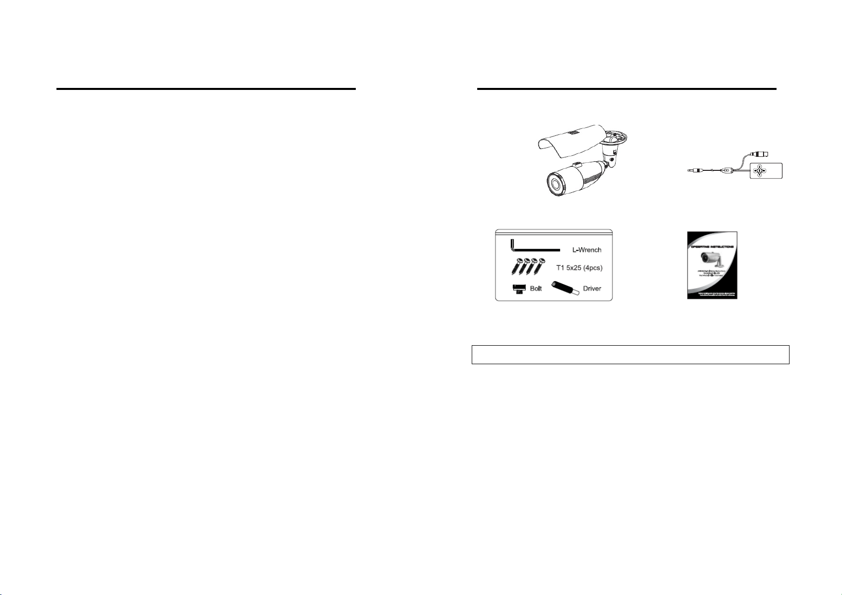
Composition
Confirm that the following parts are included:
SUN SHIELD
BRACKET
CAMERA SERVICE MONITOR AND
CONTROL CABLE
ACCESSORIES INSTRUCTION MANUAL
Explanation for Accessories
▪L-Wrench : Unscrew and tighten bracket screw for pan & tilt adjustment of camera.
▪Screws : Firmly attach the bracket to the wall or ceiling.
▪Bolt : Fix the sun-shield to the camera.
▪Driver : Unscrew the service port cap.
▪Service monitor and control cable : Monitor the display screen and set up OSD menu
externally.

5
Features
1/3” Sony Super HAD ⅡHigh-resolution Color CCD
600TVL High-Resolution
f=2.8~11mm Vari-Focal, DC Auto Iris F1.2 Day & Night Lens
Built-in 2DNR, OSD function
Back Light or High Light Compensation(BLC/HLC) function
Auto switching IR-LED control by photocell
- IR LED : 36pcs
Built-in Service monitor port & External OSD Set-up Port
Cable managed bracket
Weatherproof Housing(IP-66)
Power:DC12V
Dimension (Unit: mm)
6
Parts Name
1. Sun-Shield Bolt
2. Sun-Shield
3. Front Case
4. Rear Case
5. Service Monitor Port Cap DC12V TYPE
6. Bracket VIDEO-OUT
7. Video / Power Cable POWER
7
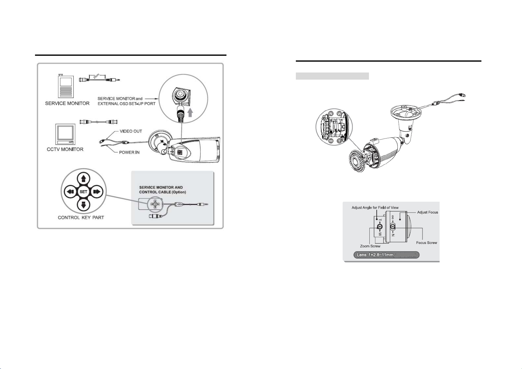
Connections
▪Power connection
- DC12V Type : Requires DC12V.(Polarity)
▪All camera models are supplied with second with second video output on
the camera model. To use this feature along with a service monitor, service
monitor cable/connector is required.
▪To set up OSD menu externally, service monitor and control cable is
required.
8
Adjustments
[Adjusting Camera View]
1. Unscrew Front Case from the Rear Case.
2. Loosen Zoom &Focus screws and make necessary adjustment as shown.
- Field of View : Telephoto(T) to Wide(W)
- Focus : Near(N) to Infinity(∞)
3. If OSD menu set-up is necessary, refer to page 11 of this manual for
further instructions.
4. Tighten Front Case back to Rear Case.
5. Cover the Sun-Shield on the camera and fix it with the Sun-shield bolt.
9
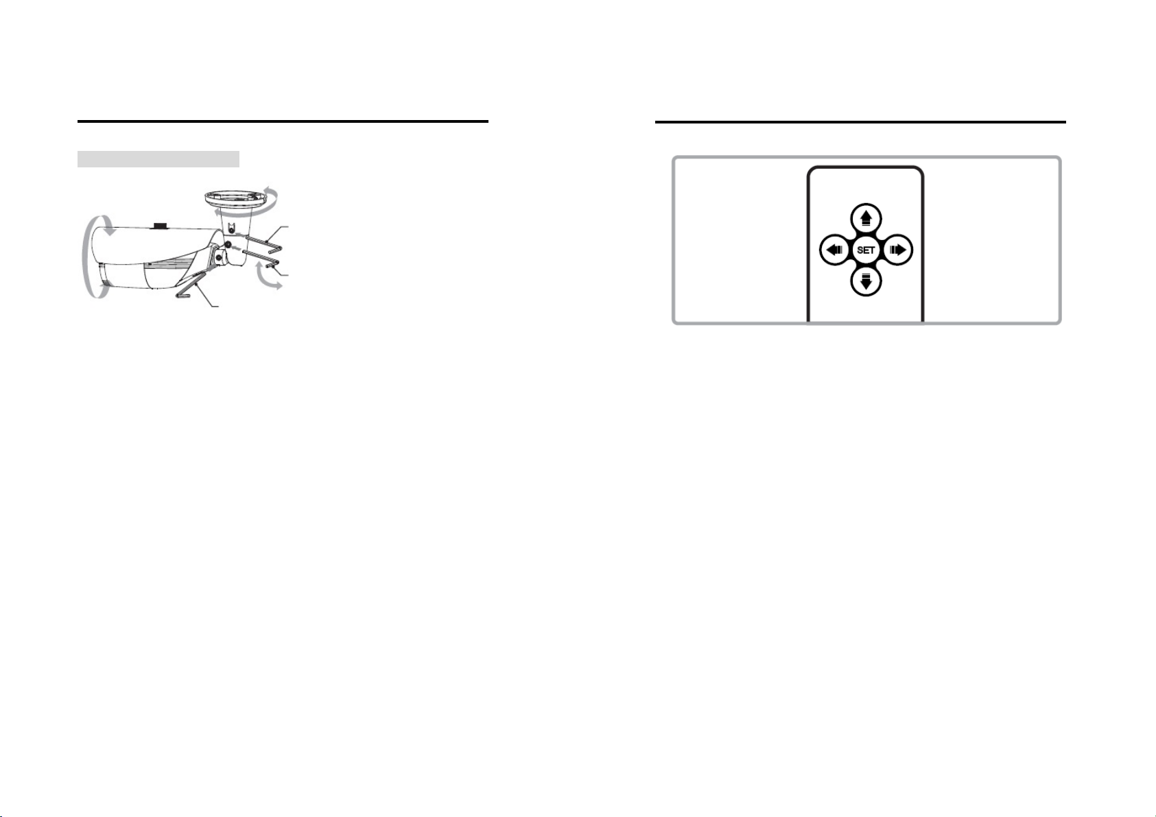
Adjustments
[Adjusting Camera View]
PAN : Adjusting view directions
TILT : Adjusting view angle
ROTATION : Adjusting screen view
▪Bracket(Cable Managed Bracket)
- Install the Mounting Bracket at the desired location. Using supplied
screws fix a bracket to the wall.
- Adjusting pan & tilt with supplied wrench the camera angle.
10
OSD Menu Instructions
1. OSD Control Key (Service Monitor and Control Cable)
■OSD Menu Control
> SET Key: Access to the menu or confirm the setting.
To enter the main menu, press the Set Key down once.
> UP/DOWN key(▲▼): Choose the desired sub-menu.
> LEFT/RIGHT key ( ): Set up the value of the selected menu.
Used to adjust the desired menu selection, and to move the cursor left or right.
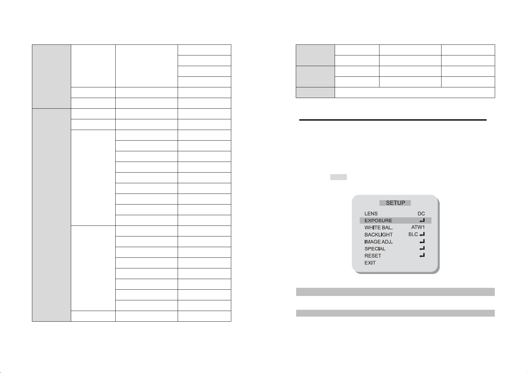
2. Menu Table
11
MAIN MENU CONFIGURATION
LENS DC
EXPOSURE SHUTTER AUTO, 1/60, FLK, 1/250, 1/500,
1/1000, 1/2000, 1/4000, 1/10000
BRIGHTNESS 0 ~ 255
AGC OFF, LOW, MIDDLE, HIGH
DWDR RET / END
RETURN
WHITE BAL. ATW1
ATW2
AWC →SET AWC →SET(PUSH)
MANUAL COLOR TEMP. MANUAL
BLUE 0~255
RED 0~255
RETURN RET / END
COLOR TEMP. INDOOR
BLUE −
RED −
RETURN RET / END
COLOR TEMP. INDOOR
BLUE −
RED −
RETURN RET / END
BACKLIGHT OFF
BLC AREA SEL AREA1 / AREA2
12
AREA STATE ON / OFF
GAIN 0~255
HEIGHT 0~15
WIDTH 0~15
LEFT / RIGHT 0~15
TOP / BOTTOM 0~15
RETURN RET / END
HLC LEVEL 0~255
MODE ALL DAY
NIGHT ONLY
RETURN RET / END
IMAGE ADJ.
LENS SHAD. ON / OFF
2DNR ON / OFF
MIRROR ON / OFF
FONT COLOR
FRONT 0~15
IND & TITLE 0~15
RETURN RET / END
COMTRAST 0~255
SHARPNESS 0~31
DISPLAY CRT PED LEVEL(0~63)
COLOR GAIN(0~255)
RETURN(RET/END)
LCD GAMMA(0.05~1.00)
PED LEVEL(0~63)
COLOR GAIN(0~255)
RETURN(RET/END)
13
USER GAMMA(0.05~1.00)
PED LEVEL(0~63)
COLOR GAIN(0~255)
RETURN(RET/END)
NEG. IMAGE ON / OFF
RETURN RET / END
SPECIAL CAM TITLE
DAY & NIGHT
MOTION AREA SEL. AREA 1~ AREA 4
AREA STATE ON / OFF
HEIGHT 0~15
WIDTH 0~15
LEFT . LIGHT 0~15
TOP / BOTTOM 0~15
DEGREE 0~255
VIEW ON / OFF
RETURN RET / END
PRIVACY AREA SEL.
AREA STATE
HEIGHT
WIDTH
LEFT . LIGHT
TOP / BOTTOM
COLOR
RETURN
DPC AUTO DEFECT(64POINT)
14
OSD Menu Instructions
3. Menu Setup
The Setup is used to control and adjust the many features and options available on
your camera. Read thoroughly before making any adjustments.
Note : These options have been pre-configured at the factory for optimal performance.
Altering these settings are not recommended.
1) Press the SETUP key to access the menu mode.
2) Select the desired feature by using UP/DOWN keys.
LENS
This is always set on DC and cannot be changed.
EXPOSURE
VERSION 00,00,01
RETURN RET / END
RESET
FACTORY RESET
RETURN RET / END
EXIT

15
OSD Menu Instructions
▪ SHUTTER : (AUTO, FLK, 1/60(1/50) ~ 1/100,000)
The SHUTTER speed can be selected manually to user preference.
Typically, to track fast moving objects across your screen, a faster shutter speed is
used. The shutter speed of 1/60(NTSC), or 1/50(PAL) seconds are recommended.
> AUTO: Select the AUTO mode for automatic adjustment of the shutters.
It will slow down or speed up depending on the environment.
> FLK: Select the FLK mode if the screen flickers due to differences in light and
electric frequencies.
●BRIGHTNESS: 0~255
The BRIGHTNESS can be adjusted by opening and closing of the Iris aperture. User
may fine-tune the screen to their preferred brightness. The brightness ranges from
0~255. (0 being darkest and 255 being the brightest possible)
●AGC (Automatic Gain Control) : OFF, LOW, MIDDLE, HIGH
This function is used to amplify the video signal when it falls below the set parameter.
As the AGC level increase, the overall screen gets brighter but the level of noise is
increased.
Note: The AGC feature cannot be modified white Day&Night mode is set to AUTO. By
factory default, AGC is automatically set on “MIDDLE”.
●DWDR (Digital Wide Dynamic Range): ON, OFF
Side Dynamic Range works to correct excessive light within the frame to produce a
usable image. It works by calculating the ratio betrwwn the brightest and darkest
values of the picture and determines the balanced medium.
●RETURN: RET, END
Selects “RET” to go back to the main menu. Select “END” to save and exit.
OSD Menu Instructions
16
WHITE BAL.
This function is used to control the while balance under different lighting conditions.
Adjusting this setting calibrate the camera for correct color rendering. The factory
default of ‘ATW1’ is recommended for optimal performance.
●ATW1 (Auto Tracking White Balance mode 1):
Select the ATW1 mode to automatically adjust the color temperature according to its
ambient condition. (2,300~9,500K)
●ATW2:
Select the ATW2 mode if the color temperature of the light source is between
2,000~11,000K.
●AWC (Auto White Balance Control):
Use the AWC function to correctly calibrate the white balance of the camera. While in
this mode, press the SET key while placing a white sheet of paper in front of the
camera. Repeat this procedure if there is a change in location or light source.
●MANUAL: INDOOR, OUTDOOR, MANUAL
If you press the SET key, you can adjust color temperature manually.
The Blue and Red values can be adjusted independently only in the Manual mode.
- INDOOR: Sets the color temperature properly for the indoor condition.
- OUTDOOR: Sets the color temperature properly for the outdoor condition.
- MANUAL: Adjust the strength of the red color or the clue color manually.
BACKLIGHT
This function is used to compensate for exposure problem associated with extremely
bright backgrounds causing the subjects to bloom or silhouette.
●BLC (Back Light Compensation):
The BLC divides the frame and calculates exposure levels of each zone to
counterbalance excessive background light in order to distinguish the subject in the
foreground. There are 2 white boxes representing the areas affected by BLC. Each
box can be individually adjusted to user preference.
OSD Menu Instructions

17
> AREA SEL. (AREA1~AREA2) : Choose one of two pre-defined boxes to adjust its
size or location.
> AREA STATE (ON,OFF): Select a box active or inactive for BLC.
> HEIGHT, WIDTH: Adjust the height or width of the area.
> LEFT/RIGHT, TOP/BOTTOM: Changes the location of the defined area.
> RETURN: Select RET to save and exit, and to go back to the MAIN MENU.
●HLC (High Light Compensation):
The HLC masks out excessively bright areas within the frame and compensates the
rest accordingly.
> LEVEL(0~255): Choose the intensity of the HLC.
> MODE(ALL DAY,NIGHT ONLY): Choose the preferred mode. ‘ALL DAY’ keeps the
HLC mode on day or night, and ‘NIGHT ONLY’ only during night mode.
IMAGE ADJ.
●LENS SHAD. : 0~255
Convex shape of the lens causes the light to enter the camera unevenly and typically
makes the center of the screen brighter than the rest. Adjusting this setting will
compensate for this undesirable effect and make the screen more even.
●2DNR (Digital Noise Reduction): ON, OFF
The DNR improves picture quality by filtering out signal noise associated with night-
time recording. DNR compares pictures from a frame with the one previous and
removes noise grains not present before.
●MIRROR : ON, OFF
This function is used to inverse the pictures coming from the camera.
OSD Menu Instructions
18
●FRONT COLOR
Change the OSD menu front color to user preference when there isn’t enough contrast
between the picture and the menu to distinguish the letters.
> FRONT: Choose from the 15 available colors.
> ID&TITLE: Choose from the 15 available colors.
●CONTRAST : 0~255
Adjust the contrast of image, the difference between light and dark areas on the
screen.
●SHARPNESS : 0~31
Adjust the display image sharpness.
●DISPLAY : CRT, LCD, USER
Selecting the correct type of viewing monitor will ensure the most optimal picture.
●NEG. IMAGE : ON, OFF
This function reverses the pictures to view in inverse.
Light to dark and vice versa.
●RETURN
Selects “RET” to save and exit, and to go back to the MAIN MENU.
SPECIAL
This function is used to control the CAMERA TITLE, DAY&NIGHT, MOTION, PRIVACY,
DPC, and display the VERSION number of the camera.
●CAM TITLE: ON, OFF
The CAMERA TITLE is used to assign a number or a custom title to easily identify
between the many cameras that may be connected to your DVR.
OSD Menu Instructions

19
Programming the camera ID:
1. Press the LEFT or RIGHT key to turn On the Camera Title mode.
2. While Camera ID function is On, press the SET key to enter the sub-menu.
3. Using the directional navigation keys, choose from alphabetical letters and numbers
to create a 15-digit Camera ID.
4. Move the cursor to POS and press the SET key.
The Camera ID will appear on the bottom center.
5. Using the directional navigation keys, change the position of the Camera Title to the
desired location.
6. Move the cursor to END, then press the SET key to save and exit.
●DAY & NIGHT : AUTO, COLOR, B/W, EXT
This function is used to control the color setting during daytime and night-time
operation.
> AUTO : The Color mode is operated during daytime and automatically converts to
B/W mode in the absence of light during night-time.
AGC cannot be modified in this mode.
D →N Level –
This level determines the level of darkness before switching from Day mode to
Night mode.
D →N Delay –
This function is used to set the delay between switching of the modes.
If the delay has been set to ‘3’, the camera will observe darkness for at least
3 seconds before switching to Night mode.
N →D Level – Opposite of D →N Level.
N →D Delay – See above D →N Delay.
> COLOR: The camera is always in Color mode.
> B/W: The camera is always in B/W mode.
BRUST OFF - This function smooths out noise in BW mode.
OSD Menu Instructions
20
BURST ON - This function makes the transition between switching of the modes
smoother when Color turns to BW.
IR SMART (ON/OFF) – This function detects too much IR reflection and automatically
compensates for the over exposure. Specific area can be defined by adjusting the
location and size of the detection grid.
IR LEVEL (HIGH/LOW) – This function is used to higher or lower the IR LED intensity.
> EXT: This feature is not supported.
●MOTION : ON, OFF
This function is used to detect motion in the monitored area.
The “Running Man” icon will be displayed on the bottom left corner once motion has
been detected. There are 4 pre-defined white boxes representing the areas monitored
for motion. Each boxes van be individually adjusted to user preference.
> AREA SEL. (AREA1~4): Choose one of four pre-defined boxes to adjust its size or
location.
> AREA STATE (ON,OFF) : Select a box active or inactive for motion detection.
> HEIGHT, WIDTH: Adjust the height or width of the area.
> LEFT/RIGHT, TOP/BOTTOM: Changes the location of the defined area.
> DEGREES (0~255): Increase or decrease the sensitivity of the selected area.
Increasing the number decreases sensitivity.
> VIEW (ON,OFF): Truns the “Running Man” indication On or Off.
> RETURN: Select RET to save and exit, and to go back to the MAIN MENU.
●PRIVACY : ON, OFF
This function is used to mask specific areas within the frame of the camera to be
concealed. There are total of 8 different colored boxes representing the masked areas.
Each boxes can be individually adjusted to user preference.
OSD Menu Instructions

21
> AREA SEL. (AREA1~8): Choose one of 8 colored boxes to adjust its size or location.
> AREA STATE (ON,OFF): Select a box active or inactive for privacy masking.
> HIGHT, WIDTH: Adjust the height or width of the area.
> LEFT/RIGHT, TOP/BOTTOM: Changes the location of the defined area.
> COLOR (1~15): Choose one of 15 colors for the masked area.
> VIEW (ON, OFF): Turns the “Running Man” indication On or Off.
> RETURN: Select RET to save and exit, and to go back to the MAIN MENU.
●DPC (Dead Pixel Compensation)
This function is used to compensate for the dead pixel areas of the screen. When a
defective pixel is detected, a neighboring pixel information is used to determine the
approximate pixel data and is replaced. The DPC is capable of compensating up to 64
points of dead pixels.
●VERSION
The camera firmware version is displayed.
●RETURN
Selects “RET” to save and exit, and to go back to the MAIN MENU.
RESET
This function is used to reset all camera settings to the factory default settings.
EXIT
Choose EXIT to save and exit from the menu mode.
22
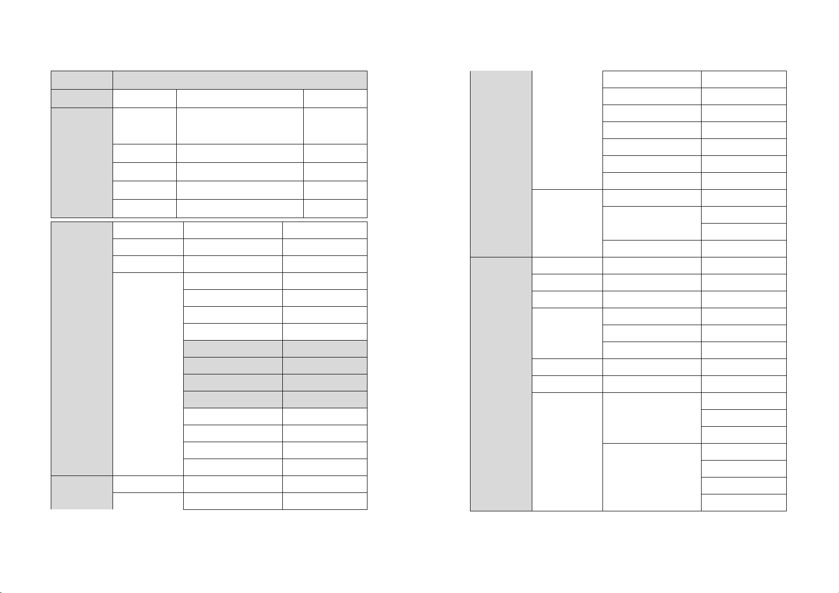
Specifications TBK-BUL4700EIR36
(*) Use regulated & specified power supply.
ITEM NTSC PAL
Image Sensor 1/3” Interline Transfer Type Color CCD (Sony)
Effective Pixels 768H x 494V (380K pixels) 752H x 582V(440K pixels)
Scanning System 525 Lines 2:1 Interlace 625 Lines 2:1 Interlace
Scanning Frequency 15.734KHz(H), 59.94Hz(V) 15.625KHz(H), 50Hz(V)
Shutter Speed 1/60sec, FLK,
Auto(1/60~1/100,000sec)
1/50sec, FLK,
Auto(1/50~1/100,000)sec
Resolution 600TVL(Color), 650TVL(B/W)
S/N Ratio More than 48dB (AGC Off)
Sync. System Internal
White Balance ATW1 / ATW2 / AWC / Manual
(ATW1: 2,300~9,500˚K, ATW2: 2,000~11,000˚K)
OSD Built-in
DNR On/Off
Day & Night
Functionality ICR type on AUTO(photocell)
Min. Illumination 0 Lux (IR-LED On)
Lens f=2.8~11mm Vari-Focal, DC Auto Iris F1.2 D/N Lens
Lens Mount C/CS Mount
Video Output VBS 1.0 Vp-p (75ΩLoad)
Power Supply (*) DC12V±10%
Power Consumption 36LEDs Max.:480mA/DC12V
Operating Temp. -10 ~ +50
Operating Humidity Max. 90% RH
Dimension 80mm(φ) x 192mm(L sin soporte) x 226mm(L total)

23
2DNR Day & Night IR-LED Vari-focal Bullet Camera
MADE IN KOREA
Table of contents
Other TBK Security Camera manuals


