TCAM Tmas T61 Installation manual

T61 Smart Modem
Hardware User Guide
V1.4
Supporting:
Firmware Version: V20040
Model: T61-ELS61
T61-EHS5
Date: 2020-08-18

Copyright 2014, TCAM Technology Pte Ltd. All Rights Reserved.
This document (T61 Smart Modem Hardware User Guide) contains information that is
proprietary to TCAM Technology Pte Ltd. No part of this document may be copied, or
reproduced in any form or by any means, or transferred to any third party without prior
written consent of TCAM Technology Pte Ltd. The content of this document may be revised
without prior notice.

T61 Smart Modem Page 3 of 47
User Guide V1.4
Table of Contents
1 Introduction .......................................................................................................................................5
1.1Related Documents............................................................................................................................ 5
1.2Product Label ..................................................................................................................................... 5
1.3Certification Test................................................................................................................................ 6
2 Device Overview ................................................................................................................................7
2.1Key Specification at a glance.............................................................................................................. 7
2.2Block Diagram .................................................................................................................................... 9
3 Special Features...............................................................................................................................10
3.1Dual IP Connection...........................................................................................................................10
3.2Self-Recovery ...................................................................................................................................10
3.3DDNS IP Update ...............................................................................................................................11
4 Hardware Interface Description ......................................................................................................12
4.1Overview..........................................................................................................................................12
4.2Interface Variant..............................................................................................................................13
4.34-Pin Micro-Fit Interface..................................................................................................................14
4.4SIM Interface....................................................................................................................................14
4.5Status LED ........................................................................................................................................ 15
4.6Antenna Interface ............................................................................................................................15
5 Mechanics, Mounting and Packaging ..............................................................................................16
5.1Mechanical Dimensions...................................................................................................................16
5.2Mounting T61 Smart Modem ..........................................................................................................17
5.3Packaging ......................................................................................................................................... 17
5.4Cable connection - T61-EHS5 modem and Landis & Gyr Meter......................................................18
6 Get Started.......................................................................................................................................19
6.1Box Open..........................................................................................................................................19
7 Device Configuration .......................................................................................................................20
7.1Initial Setup ...................................................................................................................................... 20
7.2Switching Between Smart Modem Mode and Normal Modem Mode............................................23
7.2.1 Switch to Normal Modem Mode................................................................................................23
7.2.2 Switch to Smart Modem Mode ..................................................................................................26
7.3Smart Modem Configuration...........................................................................................................27
7.3.1 General Guidelines for Smart Modem Configuration.................................................................27
7.3.2 Mobile Network Operator (MNO) ..............................................................................................29

T61 Smart Modem Page 4 of 47
User Guide V1.4
7.3.3 T61 Device Information ..............................................................................................................29
7.3.4 Data Service Center (DSC)...........................................................................................................31
7.3.5 Command Service Center (CSC).................................................................................................. 32
7.3.6 Serial Port Setup ......................................................................................................................... 33
7.3.7 Recovery Setup ...........................................................................................................................34
7.3.8 I/O Setup (Optional Feature) ......................................................................................................35
7.3.9 Utilities…………………………………………………………………………………………………………………………………. 37
7.4Default Settings................................................................................................................................38
7.5SMS Functions..................................................................................................................................39
8 Migration from TMA-M37i, TMA-M55i and TMN-51T .................................................................... 40
8.1Normal Modem Mode .....................................................................................................................40
8.2Smart Modem ..................................................................................................................................40
9 Application Notes ............................................................................................................................42
9.1T61 Firmware Update ......................................................................................................................42
9.1.1 Direct Wire Firmware Update ....................................................................................................42
9.1.2 Firmware Update Over-The-Air ..................................................................................................43
9.2T61 Digital Input Configuration (Optional Features) .......................................................................44
9.2.1 Connection..................................................................................................................................44
9.2.2 Configuration..............................................................................................................................44
9.2.3 Testing…………………………………………………………………………………………………………………………………..44
9.3T61 SMS Features (Optional Feature).............................................................................................. 45
9.3.1 Reset T61 .................................................................................................................................... 45
9.3.2 Turn ON Digital Output...............................................................................................................45
9.3.3 Turn OFF Digital Output..............................................................................................................45
9.3.4 Configure Server IP and Port ......................................................................................................46

T61 Smart Modem Page 5 of 47
User Guide V1.4
1Introduction
This document explains the hardware related features and functionalities of T61 Smart Modem. It
can be applied to all variants of T61 models with minimum differences. The scope of this document
includes a brief device overview, detailed feature description, step-by-step device configuration
tutorial.
1.1 Related Documents
[1] T61 Smart Modem Hardware User Guide
[2] T61 Normal Modem PC Setup Manual
[3] Center Manager User Guide
[4] Gemalto® EHS5-E AT Command Set 02.000
[5] Gemalto® ELS61-E AT Command Set 02.000
1.2 Product Label
The label fixed on the top of the T61 Smart Modem comprises information listed in Table 1.
No.
Information
1
Model Name
2
Power Supply
3
Frequency Band
4
Device Serial Number
5
Device Module IMEI Number
6
CE logo
7
Marking “Product of Singapore”
8
Manufacturer Code
Table 1: T61 Device Logo Information
1
2
5
6
8
7
3
4

T61 Smart Modem Page 6 of 47
User Guide V1.4
1.3 Certification Test
T61 is certified for Safety, Emission, ESD, Immunity, RF, EMC, Water/Dust Proof etc, according to the
follow standard:
EN60950-1:2006+A11:2009+A1:2010+A12:2011+AC:2011
EN55022:2010/AC:2011
EN55024:2010
EN61000-3-2:2006 + A1:2009+A2:2009
EN61000-3-3:2008
EN62311:2008
EN301 489-7 V1.3.1 (2005-11)
EN301 489-1 V1.9.2 (2011-09)
EN301 489-24 V1.5.1 (2010-10)
EN301 511 V9.0.2 (2003-03)
EN301 908-1 V5.2.1 (2011-05)
EN301 908-2 V5.2.1 (2011-07)
IEC60529:2013 –IP51 Water-proof and Dust Proof

T61 Smart Modem Page 7 of 47
User Guide V1.4
2Device Overview
T61 is a smart gateway connecting serial devices with RS232 or RS485 interfaces to
GSM/GPRS/HSPA/LTE network. It is integrated with a 32bit ARM Cortex-M0+ core processor and a
Gemalto 3G or 4G modem module. Equipped with comprehensive features, T61 smart gateway
provides industrial standard flexibility, scalability and data reliability.
T61 Smart Modem has two operation modes, namely Normal Modem Mode and Smart Modem
Mode. In Normal Modem Mode, T61 functions as a standard 3G or 4G modem by providing a direct
serial access to a Gemalto EHS5 or ELS61 module. User could send AT command to achieve various
functions, such as SMS, GSM/GPRS/3G/4G connections for data transfer. In Smart Modem Mode,
T61 provides a transparent channel from remote end devices to their dedicated data centers. It can
be configured as server or client, accept SIM card with dynamic IP or static IP, support TCP/UDP,
schedule to connect, connect on demand or “always on” connection, and with Auto Recovery, Re-
connection and Redundancy mechanisms.
As compare to PSTN or GSM dial up line or lease line, T61 smart gateway allows you to migrate your
remote device from traditional serial communication system to the advance GPRS or 3G/ 4G link,
without tedious application development or in depth knowledge of AT command or GPRS/ 3G/ 4G.
You can view this device as the “virtual serial wire over the air”, that links all your remote equipment
to the central PC. It can be a full transparent, protocol independent gateway, used for AMR, SCADA,
general remote monitoring, control and data exchange applications. It is designed for mission critical
industrial applications.
Two operation modes:
Normal Modem: The Data Terminal Equipment (DTE, such as PC, PLC, energy meters,
controller etc.) is intelligent and can issue various AT commands to T61 normal modem as
DCE (Data Communication Equipment) to establish SMS send /receive, GSM/GPRS/HSPA/LTE
dial up connection etc.
Smart Modem: In this mode, T61 Smart Modem can be configured with all essential
parameters to manage connections. It connects to assigned data centre server automatically
upon power up and sets up a transparent serial-to-wireless communication channel
between remote devices and data centre. During operation, T61 Smart Modem can maintain
the wireless connection and re-establish connection to data centre server in case of
connection lost. It can monitor site conditions or connections status, such as signal strength,
online/offline etc. It shall be an easy retro-fit solution for existing wired system to 3G/ 4G
mission critical wireless system.
2.1 Key Specification at a glance
Specifications
T61 –EHS5
T61-ELS61
General
Wireless Module
Built in with Gemalto EHS5-E
Built in with Gemalto ELS61-E
CPU
32 bits ARM Cortex-M0+
Transfer Protocol
TCP/UDP
Operational Mode
Normal Modem1or Smart modem2(Client or Server mode)
SIM card
1.8/3V, dynamic or static IP

T61 Smart Modem Page 8 of 47
User Guide V1.4
Internet Connections
Primary : Data Channel
Secondary : Command Channel
Memory*
1M Bytes
RF Specifications
Frequency Band
GSM/GPRS/EDGE: GSM 900/1800MHz
UMTS/HSPA+: UMTS 900/2100MHz
GSM/GPRS/EDGE: GSM 900/1800MHz
UMTS/HSPA+: UMTS 900/2100 MHz
LTE: 700/800/900/1800/2100 MHz
Output Power
2W for GSM/GPRS/EDGE 900MHz
1W for GSM/GPRS/EDGE 1800MHz
0.25W for UMTS (900/2100MHz)
2W for GSM/GPRS/EDGE 900MHz
1W for GSM/GPRS/EDGE 1800MHz
0.2W for LTE (700/800/900/1800/2100MHz)
GPRS
Multi-slot class 12
Full PBCCH support
Mobile Station Class B
Coding Scheme 1 –4
Multi-slot class 12
Full PBCCH support
Mobile Station Class B
Coding Scheme 1 –4
Data Rate (max.)
DL 921Kbps, UL 921Kbps
DL10.2 Mbps, UL5.2 Mbps
Antenna Interface
SMA Female 50ohm
Serial Specification
Electrical Standard
RS232 (DB9 Pin 1,2,3,4,5,7,8) or *RS485 (Pin 6,9)
Connector type
DB9 Female
Baud Rate
Normal Modem:
RS232: 1200–
921600bps
Smart Modem:
RS232: 300–
460800bps
Normal Modem:
RS232: 1200–
921600bps
RS485: 1200–
115200bps
Smart Modem:
RS232: 300–
460800bps
RS485: 300–
115200bps
Flow Control
None or
Hardware RTS, CTS, DTR, DCD (RS232 only)
None or
Hardware RTS, CTS, DTR, DCD (RS232 only)
Other Interfaces
DI* / AI*
1 x DI or AI (1.8V 16bits ADC)
DO*
1 x DO open collector, max rating 1A, 48VDC
Status LED
3mm Red
Power Supply
Connector Interface
Micro-Fit 3.0- 4pins
Supply Voltage
5-32 VDC
Supply Current (Ave)
@5VDC
@32VDC
@5VDC
@32VDC
Idle
55mA
10mA
55mA
10mA
Data Transfer (worst case)
850mA
150mA
850mA
150mA
Mechanical
Enclosure Material
Polycarbonate
Dimension
(Enclosure L x W x H)
70x53x20mm
Weight
60g
Mounting
Clip with Din Rail or screw mounting
Environmental
Operating Temperature
-25 to +85 °C
Relative Humidity
90%
Water and Dust Proof
IP51
* Features are optional.

T61 Smart Modem Page 9 of 47
User Guide V1.4
2.2 Block Diagram
Figure 1 shows a block diagram of a sample configuration that incorporates T61 Smart Modem and
typical accessories.
Figure 1: Block Diagram

T61 Smart Modem Page 10 of 47
User Guide V1.4
3Special Features
In this section, some of the new features of T61 Smart Modem are discussed in detail. This is for
better understanding of the device operation in smart modem mode. If your device is utilized in
normal modem mode, please skip this section.
3.1 Dual IP Connection
T61 Smart Modem provides two connection channels for easy handling of data and commands. One
channel is dedicated for data transfer and the other one process all control commands from
command centre or even authorized user mobile devices. This is realized by setting up two internet
connections, Data Line Connection (TCP/UDP) and Command Line Connection (TCP) (shown in Figure
2 below).
Data Line Connection: Transparent/User Defined data transfer channel. It is used for
obtaining raw data from remote devices.
Command Line Connection: Receive and process control commands. It can be used to
obtain device status, like signal strength, device ID, connection status and device current IP
etc. This connection is also used for GPRS configuration, and (firmware over-the-air) FOTA
when necessary.
These two connections can share a single server IP with different port numbers or they can be
connected to two different server IPs. Connections are set up automatically by the device. The idea
is to protect the integrity of user data with minimal interference from control commands. In the case
where command line connection is not needed, it can be simply disabled. The internet protocol for
data line connection can be customized as TCP or UDP but the internet protocol for command line
connection is always fixed as TCP.
Figure 2: Dual IP Connection
3.2 Self-Recovery
T61 Smart Gateway has built in recovery features to cater connection lost scenario. However these
features are only applicable when T61 Smart Gateway is set into smart modem mode and as a TCP
Client. Simply speaking, the device will restart itself when the server is no longer accessible. Please
pay attention to the following points regarding this recovery features.
GPRS/3G/4G
GPRS/3G/4G
RS232/*RS485

T61 Smart Modem Page 11 of 47
User Guide V1.4
Data Line Connection has higher priority. This setting is to safe guard the integrity of user
data communication. Once the device detect the data center is not accessible, it will restart
itself and try to reconnect back to the data center. In the meantime, command line
connection will break due to the reset.
Self-recovery will take effect immediately if connection lost is due to closing Center Manager
or losing GSM/GPRS/3G signal. It may take longer time if the connection lost is due to
abnormal sever shut down (i.e. connection is not properly closed).
3.3 DDNS IP Update
In order to connect the remote device to data server, IP address of data server is needed. This
becomes an issue when IP address is dynamic and changes over time. Dynamic Domain Name Sever
IP Update is implemented in T61 Smart Modem to resolve this issue. A domain name is used instead
of IP address. This is demonstrated in Figure 3.
When there is a change in IP address, server will update the new IP to our Domain Name Server so
that this new IP will be mapped to the domain name configured inside the device. Therefore, even
though the IP address is dynamic, device is always able to connect the correct IP using domain name.
Figure 3: Domain Name as Server Address

T61 Smart Modem Page 12 of 47
User Guide V1.4
4Hardware Interface Description
4.1 Overview
T61 Smart Modem provides the following interfaces for power supply, antenna, SIM card and data
transfer:
4-pin Micro-Fit Power Supply socket
SMA antenna connector (Female)
SIM card reader with cover
DB9 Connector (Female) for RS2323 or *RS485
4-Pin Micro-Fit 3.0
Socket
DB9 Connector
(Female)
SMA antenna connector
(Female)
SIM card reader with cover

T61 Smart Modem Page 13 of 47
User Guide V1.4
4.2 Interface Variant
Pin
I/O
RS232
*RS485
Description
1
O
DCD
-
2
O
Receive
-
3
I
Transmit
-
4
I
DTR
-
5
-
Ground
-
6
I/O
-
Data +
7
I
RTS
-
8
O
CTS
-
9
I/O
-
Data -
5 4 3 2 1
9 8 7 6
Figure 4: DB9 Interface

T61 Smart Modem Page 14 of 47
User Guide V1.4
4.3 4-Pin Micro-Fit Interface
T61 Smart Modem is powered by a DC with range of 5-32VDC, via 4-pin micro-Fit connector (shown
in Figure 5). The other two pins are one digital/anolog input and one digital output. Detailed pin
assignment please refer to Table below.
Pin
Description
1
VCC: 5-32 VDC
2
Ground
3
Digital Input/Analog Input
4
Digital Output
4.4 SIM Interface
The SIM –with the circuit side facing upwards –is inserted by gently pushing into the SIM card until
it snaps hold. After that, close the SIM cover for protection. The process is demonstrated above.
The SIM card cover is designed for tight locking. To open it, please open from the left side of the
cover.
To extract out the SIM card, push the SIM card inward to unlock the SIM card.
Figure 5: 4-Pin Micro Fit Interface
12
3 4
3 4
SIM extracted
SIM inserted
SIM covered

T61 Smart Modem Page 15 of 47
User Guide V1.4
4.5 Status LED
T61 Smart Modem has one red LED indicating the device and network status. When the device
detects no SIM card inserted or no antenna or not yet connected to network, the LED will blink fast
at approximately every one second. The detail “ON/OFF” timing of the LED is presented in the
following table.
LED mode
Operating status of T61
Permanently OFF
T61 is not powered on
Permanently ON
T61 is in Configuration
30ms ON/470ms OFF
During data transfer
30ms ON/3970ms OFF
Registered to a network. No data transfer
500ms ON/500ms OFF
Limited Network Services/ Network not registered/ (e.g. because no
SIM/USIM, no PIN or during network search)
4.6 Antenna Interface
An external antenna is connected via the T61’s female SMA connector (shown in Figure 6).
Figure 6: Antenna Interface

T61 Smart Modem Page 16 of 47
User Guide V1.4
5Mechanics, Mounting and Packaging
5.1 Mechanical Dimensions
T61 Smart Modem Page 17 of 47
User Guide V1.4
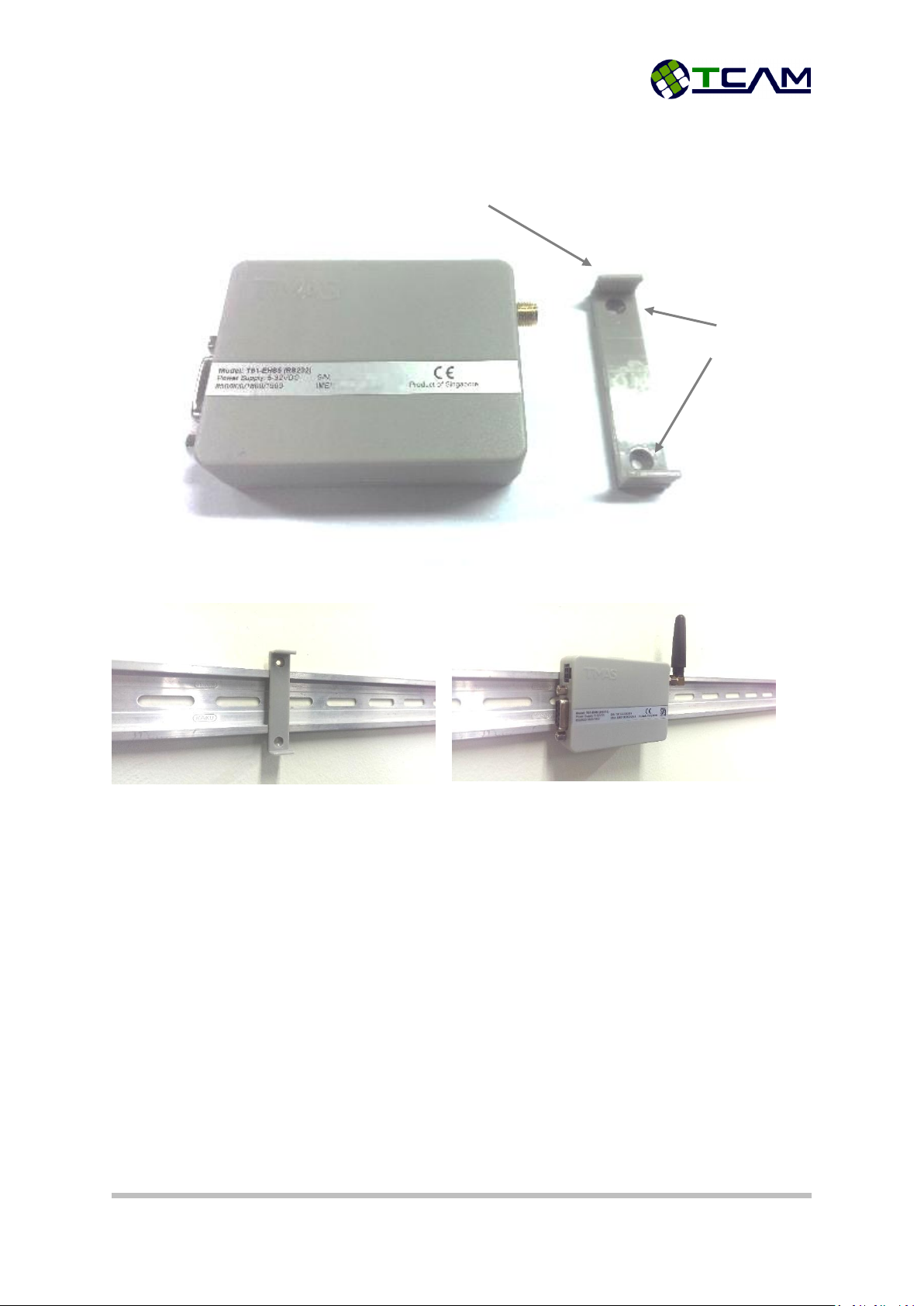
5.2 Mounting T61 Smart Modem
T61 is equipped with a mounting clip as shown in Figure 7.
To mount the device, first please fix the mounting clip on the wall or a DIN rail and then attach the
T61 device to the clip.
5.3 Packaging
T61 Smart Modem is available as a standalone terminal. It can be ordered without any accessories.
T61 Smart Modem Kit Set is also available.
T61 Smart Modem Kit Set includes all necessary accessories:
T61 Smart Modem Terminal
AC/DC power adapter with 4-pins Micro-Fit plug, DC 12V, 1A
Female-to-male DB9 modem cable
Quad-band Antenna (2dBi)
TMAS Center Manager Software
Mounting Clip
M3 Mounting Holes
Figure 7: T61 with mounting clip

T61 Smart Modem Page 18 of 47
User Guide V1.4
5.4 Cable connection - T61-EHS5 modem and Landis & Gyr Meter
Part Number: T61-ZMD-01 Cable connection to modem
Cable Connection Layout
To Landis & Gyr Meter
To T61-EHS5/ T61-ELS61
CAT5E
DB9 (Male)
Pin
Signal
Pin
Signal
1
-
2
CTS
8
CTS
3
RX
2
RX
4
GND
5
GND
5
GND
5
GND
6
TX
3
TX
7
-
Microfit - 4pins
8
VDD
1
VDD
2
GND
2
1
AC/DC power
adapter
Antenna
T61 Smart Modem
Terminal
DB9 Cable
Center Manager
Software

T61 Smart Modem Page 19 of 47
User Guide V1.4
6Get Started
T61 Smart Modem is a plug-and-play device. After simple configuration it will be ready to carry out
its mission. This section will guide you step-by-step to setup your device. For a more intuitive setup
guide, you can also watch our video guide online (https://www.youtube.com/watch?v=0YXLVhjDXEA).
The video guide is also included in the Center Manager Installation CD.
6.1 Box Open
T61 Smart Modem Kit Set will be delivered with all necessary accessories inside.
Before starting the setup, please make sure your SIM card and power socket is ready. Unpack
everything from the box and follow the steps below:
Step 1: Open the SIM card cover from left using a sharp pointer.
Step 2: Insert your SIM card into the tray with circuit side facing upwards. Close the SIM
cover.
Step 3: Screw the antenna to the SMA connector. Please be gentle, over screwing may cause
damage to the device.
Step 4: Off your socket power and plug in the adapter. Connect the square head to the
device’s power socket.
Now your device is ready to power up.

T61 Smart Modem Page 20 of 47
User Guide V1.4
7Device Configuration
T61 Smart Modem is robust and comprehensive. Most of its properties are configurable to cater
different requirements. In this chapter, all configuration options will be discussed.
There are two ways to configure T61 Smart Modem. One way is using TMAS Center Manager
software (Refer to the Center Manager User Guide). The other way is to use serial terminal software.
And terminal software will do the job, while HyperTerminal and Hercules are recommended. A
configuration menu is embedded inside T61 smart gateway. User can easily configure the device via
serial port. In this chapter, we will focus on the serial port configuration method. All screenshots are
taken using HyperTerminal.
7.1 Initial Setup
To configure T61 smart gateway, serial terminal software should be configured as followed:
Baud Rate: 115200bps
Data Bits: 8
Parity Bit: None
Flow Control: None
The factory default operation mode of T61 smart gateway is Normal Modem Mode, switch to Smart
Modem Mode before you continue. After powering up the device, you will see the start-up menu
shown in Figure 8. This start-up menu includes device mode, firmware version and product serial
number.
Figure 8: Start-up Menu
This manual suits for next models
2
Table of contents
Popular Modem manuals by other brands

Patton electronics
Patton electronics 3012/V24, 3014/V24, 3018/V24 Installation and operation manual

Abocom
Abocom FM560C Quick installation guide

Bentel Security
Bentel Security B-Mod2 manual

Clarion
Clarion M10II JX4000W-A user guide

Westermo
Westermo ODW-621 user guide

Motorola
Motorola SB5101 - SURFboard - 30 Mbps Cable Modem Quick reference guide


