TCL CTR1042 User manual

Service
Service
Contents Page
1. Technical Specifications, Connections and Chassis Overview 2 - 3
2. Safety & Maintenance Instructions, Warningsand Notes 4 - 5
3. Directions for Use 6 - 32
4. Mechanical Instructions 33
5. Faultfinding 34 -40
6. Block Diagram, I2C
Overview Block Diagram 41
2
I C 42-43
7. Electrical Diagrams and Test Point with waveform diagram
Power Supply (Diagram A1) 44
Line Deflection (Diagram A2) 44
Frame Deflection (Diagram A3) 45
Tuner IF (Diagram A4) 45
MCU,Video IFand Sound IF (Diagram A5) 46
BTSC (Stereo/SAP) Decoder(Diagram A6) 47
Video Source Switching (Diagram A7) 47
Side AV (Diagram A8) 48
Audio Amplifier(Diagram A9) 48
CRT Panel (Diagram B) 49
Transistor Test Voltage 49
Test point with Waveform Diagram 50 - 51
8. PCB diagram
Main PCB 52
CRT PCB 53
MPX PCB 54
SIDE AV PCB 55
9. AlignmentProcedures 56 - 64
10. Circuit Description 65
11. List of Abbreviations 66 - 68
12. Spare Parts List 69 - 89
©Copyright 2001 Philips Consumer Electronics B.V. Eindhoven, The Netherlands.All
rights reserved. No part of this publication may be reproduced, stored in aretrieval system or
transmitted, in any form or by any means, electronic, mechanical, photocopying, or otherwise
without the prior permission of Philips.
Colour Television Chassis: M123A
1

Index:
Note:
Below described specifications are not valid
for one product, but for the whole product
range.
See Product Survey for specific models.
Figures can deviate slightly from the actual
situation, due to different set executions.
1. Technical Specifications.
2. Connections.
3. Chassis Overview.
1.1 Technical Specifications
1.1.1 Reception
Tuning system : PLL
Colour systems : NTSC-M
Sound systems : FM-mono: FM-stereo
A/V connections: NTSC 3.58
Channel selections :TV:2-69,CATV:2-13,A-W,
W+1~W+84,A-5~A-1,5A
Aerial input: 75OHM, 1VP-P
Audio output: =3W+3W
Mains voltage : AC120V
Mains frequency : 60 Hz
Ambient temperature: + 5 to + 45 deg. C
Maximum humidity : 90 %
Power consumption : 80W
Standby Power consumption : <3W
1.1.2 Miscellaneous
1.2 Connections
1.2.1 Side Connections and Front Control
IN1
AUDIO
VIDEO
S-VIDEO
L
(MONO)
R
SIDE AV PANEL
A/V In
1 - Audio R(0.5 Vrms / 1k_)
2 - Audio L(0.5 Vrms / 1 k_)
3 -Video CVBS (1 Vpp / 75 )
4 - S-video (1 Vpp / 75)
TV/AV SENSOR
STANDBY
POWER
FRONT PANEL
TV/AV
SENSOR
STANDBY
POWER
DVD INPUT
YCbCr
In2
OUT
75OHM
ANTENNA
INPUT
1.2.2 Rear Connections
DVD Input
1 - Y (1 Vpp / 75 _)
2 - Cb(1 Vpp / 75 _)
3 - Cr(1 Vpp / 75 _)
AV2 In
4 - Video CVBS (1 Vpp / 75 _)
5 - Audio L(0.5 Vrms / 10 k_)
6 - Audio R(0.5 Vrms / 10 k_)
Monitor Out
7 - Video CVBS (1 Vpp / 75 _)
8 - Audio L(0.5 Vrms / 1 k_)
9 - Audio R(0.5 Vrms / 1 k_)
Colour Television Chassis: M123A
2
1. Technical Specifications, Connections and Chassis Overview
VIDEO
AUDIOR
L--
REAR PANEL

Colour Television Chassis: M123A
3
1.3 Chassis Review
7.1 Power Supplier
7.2 Line Deflection
7.3 Frame Deflection
7.4 Tuner IF
7.5 MCU, Video IF and
Sound IF
7.6 BTSC (Stereo/SAP)
Decode
7.7 Video Source
Switching
MSP PANEL
CRT PANEL
Main
Chassis
Panel
Side
AV
Panel

2. Safety & Maintenance Instructions, Warnings and Notes
2.1 Safety Instructions For Repairs
2.2 Maintenance Instructions
Safety regulations require that during a repair:
--Due to the 'hot' parts of this chassis, the set must be connected to the AC power via an
isolation transformer.
-- Safety components, indicated by the symbol _, should be replaced by components identical
to the original ones.
-- When replacing the CRT, safety goggles must be worn. Safety regulations require that after a
repair, the set must be returned in its original condition. Pay particular attention to the
following points:
-- General repair instruction: as a strict precaution, we advise you to re-solder the solder
connections through which the horizontal deflection current is flowing, in particular:
--- all pins of the line output transformer (LOT)
--- fly-back capacitor(s)
--- S-correction capacitor(s)
--- line output transistor
--- pins of the connector with wires to the deflection coil
--- other components through which the deflection current flows.
* Note: This re-soldering is advised to prevent bad connections due to metal fatigue in solder
connections and is therefore only necessary for television sets more than two years
Old.
-- Route the wire trees and EHT cable correctly and secure them with the mounted cable clamps.
-- Check the insulation of the AC powercord for external damage.
-- Check the strain relief of the ACpower cord for proper function, to prevent the cord from
touching the CRT, hot components, or heat sinks.
-- Check the electrical DC resistance between the AC plug and the secondary side (only for sets
that have an isolated power supply). Do this as follows:
1. Unplug the AC power cord and connect a wire between the two pins of the AC plug.
2. Turn on the main power switch (keep the AC power cord unplugged!).
3. Measure the resistance value between the pins of the AC plugand the metal shielding of the
tuner or the aerial connection of the set. The reading should be between 4.5 M and 12 M .
4. Switch the TV OFF and remove the wire between the two pins of the AC plug.
Check the cabinet for defects, to prevent the possibility of the customer touching any
Internal parts.
It is recommended to have a maintenance inspection carried out by qualified service
personnel. The interval depends on the usage conditions:
--- When the set is used under normal circumstances, for example in a living room, the
recommended interval is hree to five years.
--- When the set is used in an environment with higher dust,grease or moisture levels, for
example in a kitchen, the recommended interval is one year.
--- The maintenance inspection includes the following actions
1. Perform the 'general repair instruction' noted above.
2. Clean the power supply and deflection circuitry on the chassis.
3. Clean the picture tube panel and the neck of the picture tube.
Colour Television Chassis: M123A
4

--- In order to prevent damage to ICs and transistors, avoid all high voltage flashovers. In order to
prevent damage to the picture tube, use the method shown in Fig. 2-1, to discharge the picture
tube. Use a high voltage probe and a multi-meter (position VDC). Discharge until the meter
reading is 0 V (after approx. 30 s).
---- AllICs and many other semiconductors are susceptible to electrostatic discharges (ESD)
Careless handling during repair can reduce life drastically. When repairing, make sure that you
are connected with the same potential as the mass of the set by a wristband with resistance.
Keep components and tools also at this potential. Available ESD protection equipment:
--- Complete kit ESD3 (small tablemat, wristband, connection box, extension cable, and ground
cable)
--- Wristband tester
--- Together with the deflection unit and any multi-pole unit, flat square picture tubes form an
integrated unit. The deflection and the multi-pole units are set optimally at the factory.
Adjustment of this unit during repair is therefore not recommended.
---- Be careful during measurements in the high voltage section and on the picture tube.
Never replace modules or other components while the unit is switched ON.
---- When you align the set, use plastic rather than metal tools. This will prevent any short circuits
and the danger of a circuit becoming unstable.
--- Measure the voltages and waveforms with regard to the chassis (= tuner) ground (), or hot
ground (), depending on the area of circuitry being tested.
---- The voltages and waveforms shown in the diagrams are indicative. Measure them in the Service
Default Mode (see chapter 5) with a color bar signal and stereo sound (L: 3 kHz, R: 1 kHz unless
stated otherwise) and picture carrier at 475.25 MHz (PAL) or 61.25 MHz (NTSC, channel 3).
---- Where necessary, measure the waveforms and voltages with () and without () aerial signal.
Measure the voltages in the power supply section both in normal operation () and in standby ().
These values are indicated by means of the appropriate symbols.
---- The picture tube panel has printed spark gaps. Each spark gap is connected between an
electrode of the picture tube and the Aquadagcoating.
--- The semiconductors indicated in the circuit diagram and in the parts lists are completely
interchangeable per position with the semiconductors in the unit, irrespective of the type
Indication on these semiconductors.
2.3 Warnings
_
4822 344 13999.
2.4 Notes
Colour Television Chassis: M123A
5

3. Directions for Use
3.1 Basic Cable TV Connection
DVD INPUT
YCbCr
IN2
OUT
VIDEOAUDIORL--
75OHM
ANTENNA
INPUT
DVD INPUT
YCbCr
IN2
OUT
VIDEOAUDIORL--
75OHM
ANTENNA
INPUT
75 OHM
ANTENNA
INPUT
75 OHM
ANTENNA
INPUT
Cable TV company
Cable TV company
Cable Box
The cable TV signal into your home
may be a single cable (75ohm) or may
include a cable Box. In either case, the
connection to the TV is easy.
If your Cable TV signal comes
directly via a 75ohm coaxial cable,
use the following steps:
Connect the Cable TV signal to
the 75 OHM ANTENNA INPUT jack
on the rear of the TV. Screw it
Plug the TV s power cord into a
power outlet and turn on the TV.
Set TV/CATV to CATV as detailed in
page11.
Refer to AUTO SEARCH to set up
your available channels. Details
are on page 12.
If you have a Cable Box, use the
following steps.
Connect the Cable TV signal to
the IN jack on the Cable Box.
Connect the separate coaxial
cable to the OUT jack on the Cable
Box and to the 75 OHM ANTENNA
INPUT jack on the rear of the TV.
Plug the TV s power cord into a
power outlet and turn on the TV.
Set TV/CATV to CATV as detailed in
page11.
Set the TV to channel 3 or 4 (the
same as the Channel3/4 switch on
your Cable Box if applicable).
Change channels at the Cable
An RF coaxial cable (to
connect the Cable Box to
the TV) may be supplied
by the Cable TV company.
It is not supplied with the
TV.
You can connect a
Satellite Receiver the
Helpful Hints
Your Cable Box may have separate Audio and Video Out
jacks instead. If so, use audio and video cables to connect
the AUDIO/VIDEO OUT jacks of the Cable Box to the
Press the TV/AV on the remote control to set the TV to the
AUDIO/VIDEO IN 2 jacks on the rear of the TV.
Colour Television Chassis: M123A
6

DVD INPUT
YCbCr
IN2
OUT
VIDEOAUDIORL--
75OHM
ANTENNA
INPUT
DVD INPUT
YCbCr
IN2
OUT
VIDEOAUDIORL--
75OHM
ANTENNA
INPUT
75 OHM
ANTENNA
INPUT
UHF/VHF
Combiner
75-300 Ohm Adapter
VHFAntenna
VHFAntenna
UHFAntenna
Rear of TV
OR
A combination antenna receives normal
broadcasting channels (VHF2-13 and
UHF 14-69). Your connection is easy
since you will connect the antenna to
the 75OHM ANTENNA INPUT jack on
the rear of the TV.
If your antenna has a round cable
(75 ohm) on the end, then you are
ready to connect it to the TV. Go to
step 2.
If your antenna has flat twin-lead
wire (300 ohm), you first need to
attach the antenna wire to the screws
on a 300 to 75 ohm adapter (not
Push the round end of the adapter or
antenna cable onto the 75 OHM
ANTENNA INPUT jack on the rear of
the TV. If the round end of the antenna
cable is threaded, screw it down tight.
Plug the TV s power cord into a
power outlet and turn on the TV. Set
TV/CATV to CATV as detailed in
page11.
Refer to AUTO SEARCH to set up
your available channels. Details are
on page 12.
If you have separate UHF and VHF antennas, you need an
optional combiner to connect to the TV.
3. Directions for Use
3.2 Basic Antenna Connection
Colour Television Chassis: M123A
7

DVD INPUT
YCbCr
DVD INPUT
YCbCr
IN2
OUT
VIDEOAUDIORL--
75OHM
ANTENNA
INPUT
DVD INPUT
YCbCr
IN2
OUT
VIDEOAUDIORL--
75OHM
ANTENNA
INPUT
DVD INPUT
YCbCr
IN2
OUT
VIDEOAUDIORL--
75OHM
ANTENNA
INPUT
IN1
AUDIO
VIDEO
S-VIDEO
L
(MONO)
R
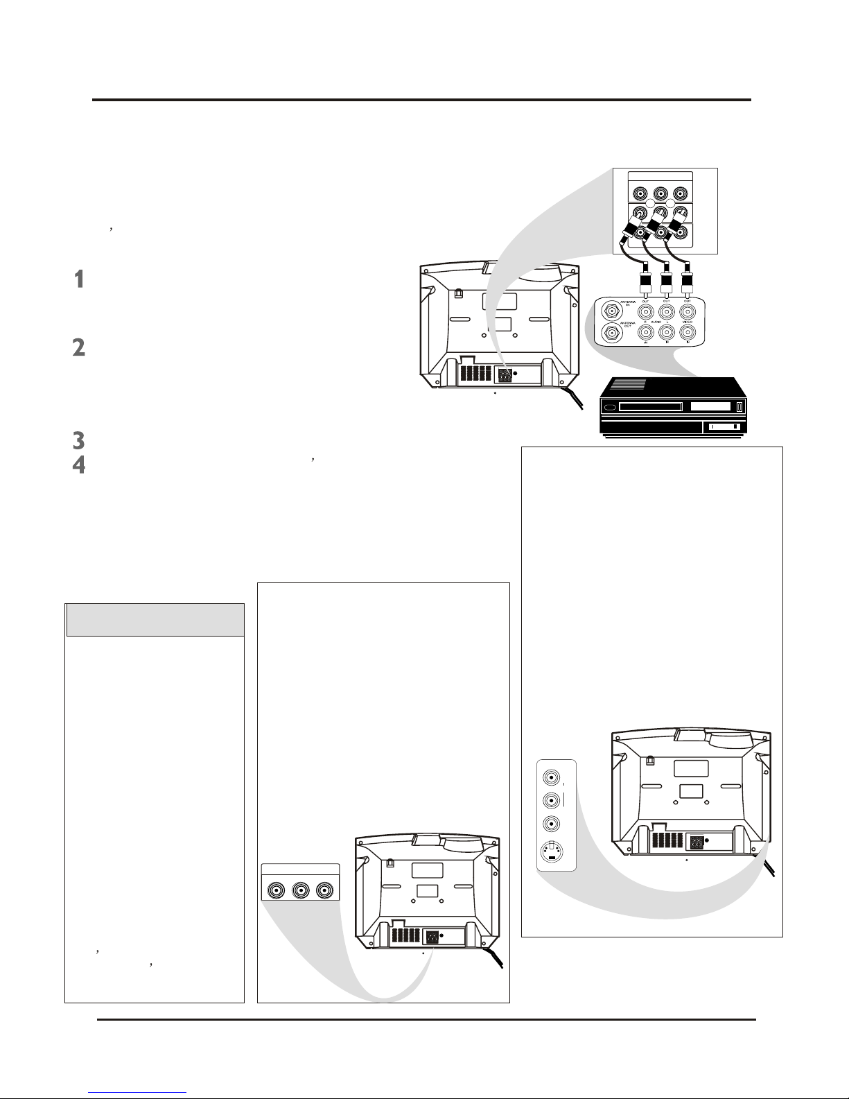
The basic Antenna/Cable TV to Accessory
(VCR, DVD Player, etc.) to TV connection is
shown at right. For other hookups (such as
those with Cable Boxes), refer to the
owner s manual of the Cable Box or other
Accessories.
Connect a yellow video cable to the
VIDEO IN 2 jack on the rear of the
TV and to the VIDEO OUT jack on
your VCR(or )other Accessories.
Connect red and white audio cables
to the AUDIO IN 2 jacks(left and right)
on the rear of the TV and to the
AUDIO OUT jacks on your VCR(or
other device.) Match the cable colors
to the jack colors.
Press the TV/AV button on the TV s
remote control until AV2 appears in the
upper right corner of the TV screen.
When you play material on the VCR,
DVD player, etc. that is connected to the
AUDIO and VIDEO IN 2 jacks on the rear
of the TV, it will appear on the TV on the
AV 2 channel.
Helpful Hints
Audio and video cables are
not supplied with the TV.
Audio cables are usually
marked with red and white.
Video cables (CVBS) are
usually marked with yellow.
You can connect the antenna
or Cable TV signal to either
the ANTENNA IN jack on your
VCR or to the 75 OHM
Your VCR may not have
Audio and Video Out jacks,
but only an RF or ANTENNA
OUT jack. Use an Therefore
coaxial cable to connect the
VCR s ANTENNA OUT jack
to the TV s 75OHM
ANTENNA INPUT jack.
ANTENNA INPUT jack on the
TV. If you connect it to the
VCR, choose TV channels at
the VCR. Connect it to the
VCR if you want to record TV
programming through VCR.
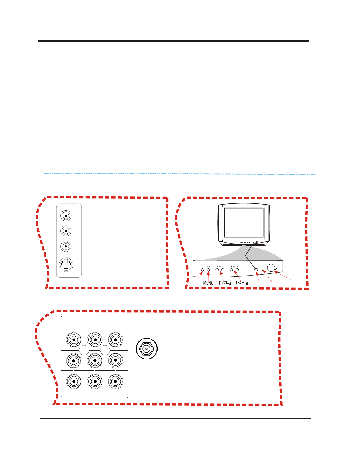
There are Component Video In jacks on
the rear of the TV. These are labelled
DVD Y, Cb and Cr and are red, blue and
green. Use these to connect a DVD
player that has Component Video Out
jacks. This will provide the best picture
quality. Use Component Video cables,
which are not supplied with the TV.
If you connect the DVD player to the
DVD jacks, set the TV to YUV channel to
watch DVD s. Press TV/AV button on the
remote so YUV appears on the TV
screen.
Use either DVD or VIDEO In2 jacks, but
do not use both for the same piece of
equipment. You only need one video
connection per each accessory(DVD
player, etc.).
There are AUDIO and VIDEO IN1 jacks at
the lower-right corner of the rear of the TV
set. To view material playing on
equipment connected here, press the
TV/AV so VIDEO 1 is on the TV.
There is also an S-VIDEO IN jack in this
area. Use S-Video connection if your DVD
player, camcorder, etc. has an S-Video
Out jack. S-Video provides a clearer
picture than the standard CVBS video
(the yellow jack). Choose the VIDEO1
channel to view material playing pn
equipment connected to the S-VIDEO IN
jack.
Use either S-VIDEO IN jack or VIDEO IN1
jacks. Do not use both at the same time
for the same piece of equipment. This
would interfere with the picture display. If
both are used, S-VIDEO IN has priority
over the yellow VIDEO In1 jack.
DVD INPUT
YCbCr
IN2
OUT
VIDEOAUDIORL--
R
R
R
Turn on the TV and the VCR.
3. Directions for Use
3.3 Basic to VCR (ACCESSORY)Connection
Colour Television Chassis: M123A
8

3. Directions for Use
3.4 Basic to Antenna Connection
Press POWER to turn on the TV.
Press VOL. to increase the sound
level. Press VOL. To lower the sound
level.
Press CH. or CH. to select TV
channels.
Press MENU to see the TV s on-screen
menu. In the menu, use VOL. / and CH.
/ button to make adjustments or
selections.
You can press MENU on either the
remote control or the front of the TV to
access or remove the menu.
Television
Remote control
Point the remote control toward the
remote sensor on the front of the TV when
operating the TV with the remote control.
Battery Installation
Remove the battery compartment lid
on the rear of the remote . Press in the
tab, then lift off the lid.
To load batteries into the remote control:
Place two AAA batteries in the remote.
Be sure the (+) and (-) ends of the
batteries line up correctly (as marked
inside the remote).
Reattach the battery compartment lid.
The channel number will
appear briefly when you
change channels. Or, press
DISPLAY on the remote to
see the channel number.
Press TV/AV on the front of
the TV to choose AV1/ S-
Video, AV2, or YUV.
Helpful Hints
TV/AV SENSOR
STANDBY
POWER
1.
2.
3.
Colour Television Chassis: M123A
9

3. Directions for Use
3.5 Remote Control
STANDBY Button
Press to turn the TV on or off(standby).
You also can turn on the TV by pressing
the CH(annel) / buttons on the front of
the TV.
SLEEP Button
Press to select a time period (120
minutes to 10 minutes in 10 minutes
decrements) after which the TV will turn
itself off. Details are on page 22.
SMART PICTURE Button
Press to select one of the four picture
settings(Personal, Movies, Sports, Weak
Signal).
Details are on page 17.
MENU Button
Press to see the TV s on-screen menu.
Press to go back to the previous menu or
to remove a menu from the screen.
VOL.(volume)+/- Button
Press to adjust the TV sound level.
DISPLAY
Press to see the current channel number
on the TV screen. Press again to display
the current time on the screen.
Press to remove a menu from the screen.
MUTE Button
Press to cancel or restore the TV sound.
Pressing the volume buttons (VOL or
VOL +) also will cancel mute and restore
the sound.
MTS Button
Press to select a sound mode if available
with the TV programming: MONO,
STEREO, SAP and MONO+SAP.
Details are on page 31.
TV/AV Button
Press to select TV channels or the Audio
/Video IN channels(AV1/S-VIDEO, AV2,
or YUV).
CH.(channel)+/- Button
Press to select memorized TV channels.
NUMBER Buttons
Press to select TV channels directly. For
single-digit channels, press two 0 first,
then the number of the channel.
For double-digit channels, press
For channels 100 and above, press
three number buttons of the channel
directly.
(You can select channels above 69 only
if you have Cable TV. Make sure
TV/CATV is set to CATV. Details are on
page 11.)
0
first, then the two numbers of the
channel. For example, to choose
channel 45, press the 0 button, then
Number 4, then Number 5.
SMART SOUND Button
Press to select one of the four sound
settings(Voice, Music, Theatre, or
Personal)
Details are on page 29.
A/CH Button
In TV mode, press to return to the
previous channel.
Note: in AV mode, press A/CH to only
enter TV mode.
OK Button
Within on-screen menu, press to enter
some special function, such as Favorite
List, etc..
FAVORITE Button
Press to browse the channels preset in
Favorite List.
Details are on page 14.
Colour Television Chassis: M123A
10

3. Directions for Use
3.6 Language
Language
You can set the TV s on-screen menu to be
in English, or Spanish.
Press MENU to see the menu.
Press VOL+ or VOL- to highlight
(Feature).
Press CH- to highlight Language.
Press VOL+ or VOL- to select
English or Espanol (Spanish).
Press M NU repeatedly to remove
the menu from the screen or menu will
quit after a few seconds without
further action.
E
The language control only
affects the language of the
TV menus. It does not
change the other on-screen
text features, such as
Closed Captions.
Helpful Hints
P. L o c k
Child Lock
English
Off
C.Capt Off
Language
Brightness
Contrast
Tint
Blue Back
Noise Red.
C. Temp
50
50
00
On
Off
Normal
Sharpness 50
Color 50
English
Language
P. L o c k
Child Lock Off
C.Capt Off
,
Colour Television Chassis: M123A
11

3. Directions for Use
3.7 TV/Cable TV (CATV)
Brightness
Contrast
Tint
Blue Back
Noise Red.
C. Temp
50
50
50
On
Off
Normal
Sharpness 50
Color 50
Add/Erase
Fine 0
Favorite list
Add
2Channel
Manual Up
TVTV/CATV
Auto search
Add/Erase
Fine 0
Favorite list
Add
2Channel
Manual Up
TVTV/CATV
Auto search
It is important for the TV to know what type
of signal-Cable TV(CATV) or a normal
antenna-you are using. To tell the TV
whether you are using a cable TV signal, set
TV/CATV to TV or CATV as follows.
Press MENU to see the menu.
Press CH+ or CH- repeatedly to
highlight TV/CATV.
Press VOL+ or VOL- to select TV or
CATV.
Choose CATV if you have Cable TV
service. (See page five for connection
details.) If you do not have Cable TV
service and you connected an
antenna to the TV, choose TV. (See
page six for connection details.)
Add/Erase
Fine 0
Favorite list
Add
2Channel
Manual Up
CATVTV/CATV
Auto search
When CATV is selected,
channels 1-125 are
available.
When TV is selected, only
channels 2-69 are available.
You cannot select Preset if
the TV is set to AV1/S-
video, AV2, or YUV. Press
TV/AV repeatedly to get to
the TV channels.
Helpful Hints
Press VOL+ or VOL- to highlight
(Preset).
Press CH- to enter Preset submenu.
Press M NU repeatedly to remove
the menu from the screen or menu will
quit after a few seconds without
further action.
E
,
Colour Television Chassis: M123A
12

3. Directions for Use
3.8 Auto Search (Setting TV Channels)
You can set your TV to receive local TV
channels (From an antenna) or Cable TV
channels(when you have Cable TV service).
Then, use AUTO SEARCH to set up
channels that are available for you. This
makes it easy for you to select only the
available TV stations when you press CH+ or
CH-. Before you start AUTO SEARCH,
connect the Antenna or Cable TV signal as
detailed on pages five-six; set TV/CATV as
described on page11.
Add/Erase
Fine 0
Favorite list
Add
2Channel
Manual Up
TVTV/Cable
Auto search
Add/Erase
Fine 0
Favorite list
Add
2Channel
Manual Up
TVTV/CATV
Press MENU to see the menu.
Press CH+ or CH- repeatedly to
highlight Auto search.
Press VOL+ or VOL- to highlight
(Preset).
Press CH- to enter Preset submenu.
Press VOL+ to start programming TV
channels. Press the VOL- if you need
to stop channel programming during
the process.
When channel setup is complete, the
TV will go to its lowest channel.
Programming
Please Wait
TV 2
Press CH+ or CH- to see
which channels are in the
TV s memory. You can still
select non-memorized
channels using the Number
buttons on the remote
control.
To delete unwanted
channels from the
You cannot select Preset
menu if the TV is set to
AV1/S- video, AV2, or YUV.
Press TV/AV repeatedly to
get to the TV channels.
TV s
memory or to add more
channels, see ADD/ERASE
on page14.
Helpful Hints
Auto search
Stop
Brightness
Contrast
Tint
Blue Back
Noise Red.
C. Temp
50
50
50
On
Off
Normal
Sharpness 50
Color 50
Colour Television Chassis: M123A
13

3. Directions for Use
3.9 Manual Channel Tunning/Fine Tuning
Manual Channel Tuning lets you quickly
select the next available channel. For
example, if you are looking for a channel
between 60 and 70, start the search at
channel 60 and go up.
Press MENU to see the menu.
Press CH+ or CH- repeatedly to
highlight Manual.
Press VOL+ to start searching
upward (for example, starting at
channel 60 and going up to 61, 62, 63,
etc.). Press VOL- when you find the
channel you want. This stop the
search. Otherwise the search will
stop at the first available channel.
Or,press VOL- to start searching
downward (for example, starting at
channel 60 and going down to 59, 58,
57, etc.). Press VOL+ when you find
the channel you want. This stop the
search. Otherwise the search will
stop at the first available channel.
Brightness
Contrast
Tint
Blue Back
Noise Red.
C. Temp
50
50
50
On
Off
Normal
Sharpness 50
Color 50
Add/Erase
Fine 0
Favorite list
Add
2Channel
Manual Up
TVTV/CATV
Auto search
Add/Erase
Fine 0
Favorite list
Add
TVTV/CATV
Auto search
Manual Up
Add/Erase
Fine 0
Favorite list
Add
2Channel
Manual Up
CATVTV/CATV
Auto search
Add/Erase
Fine 0
Favorite list
Add
Channel
TVTV/CATV
Auto search
Manual Up
Add/Erase
Fine 0
Favorite list
Add
Channel
TVTV/CATV
Auto search
Manual Down
60Channel
62
58
Press CH+ or CH- repeatedly to
highlight TV/CATV.
Press VOL+ or VOL- to select TV or
CATV(whichever you have).
Details are on page11.
Press CH+ or CH- repeatedly to
highlight Channel.
Press VOL+ or VOL- to enter the
channel number at which you want to
begin the search.
If the reception is poor, you
can select Fine to fine
tuning the channel upward
or down ward till you are
satisfied.
Helpful Hints
Press VOL+ or VOL- to highlight
(Preset).
Press CH- to enter Preset submenu.
Press M NU repeatedly to remove
the menu from the screen or menu will
quit after a few seconds without
further action.
E
,
or
You cannot select Preset if
the TV is set to AV1/S-
video, Av2, or YUV. Press
TV/AV repeatedly to get to
the TV channels.
Helpful Hints
Colour Television Chassis: M123A
14

3. Directions for Use
3.10 Favorite Channel Setting
You can store five channels you prefer into
the Favorite list and recall these channels
easily by press the FAVORITE button on the
remote control.
You cannot select Preset if
the TV is set to AV1/S-
video, AV2, or YUV. Press
TV/AV repeatedly to get to
the TV channels.
Helpful Hints
Press MENU to see the menu.
Press CH+ or CH- repeatedly to
highlight Favorite list.
Press VOL+ or VOL- to highlight
(Preset).
Press CH- to enter Preset submenu.
Press OK to display features of
Favorite list.
Press M NU repeatedly to remove
the menu from the screen or menu will
quit after a few seconds without
further action.
E
Add/Erase
Fine 0
Favorite list
Add
2Channel
Manual Up
TVTV/Cable
Auto search
Add/Erase
Fine 0
Add
2Channel
Manual Up
TVTV/CATV
Auto search
,
Brightness
Contrast
Tint
Blue Back
Noise Red.
C. Temp
50
50
50
On
Off
Normal
Sharpness 50
Color 50
Favorite list
TV/CATV
CH1
CH2
CH3
CH4
CH5
CATV
CATV
CATV
CATV
CATV
CATV
1
2
3
4
5
TV/CATV is highlighted. Press
VOL+ or VOL- to select TV or CATV
(whichever you have).
TV/CATV
CH1
CH2
CH3
CH4
CH5
CATV
CATV
CATV
CATV
CATV
CATV
1
2
8
4
5
Press CH+ or CH- to select CH3(or
Ch1, Ch2, Ch4, Ch5), then Press
VOL+ or VOL- to enter a channel
number you want to store at this
position, such as CATV 8.
Colour Television Chassis: M123A
15

3. Directions for Use
3.11 Adding or Erasing Channels
You can add or erase channels from the list
in the TV s memory.
Press MENU to see the menu.
Fine 0
Favorite list
TVTV/CATV
Auto search
Manual Up
12Channel
Press CH+ or CH- repeatedly to
highlight Add/Erase.
Press VOL+ or VOL- to choose Add
or Erase.
If you select Add, the channel will be
available when you press CH+ and
CH- to move through channels.
Choosing Erase will remove the
channel from the TV s memory. The
channel will not be available when you
flips through channels with the CH+
and CH- buttons
You cannot select Preset if
the TV is set to AV1/S-
video, AV2, or YUV. Press
TV/AV repeatedly to get to
the TV channels.
Helpful Hints
Add/Erase
Fine 0
Favorite list
Add
12Channel
Manual Up
TVTV/CATV
Auto search
Brightness
Contrast
Tint
Blue Back
Noise Red.
C. Temp
50
50
50
On
Off
Normal
Sharpness 50
Color 50
Add/Erase Add
Fine 0
Favorite list
TVTV/CATV
Auto search
Manual Up
12Channel
Add/Erase
Erase
Using the Number buttons, select
the channel you wish to add or erase.
12
Press M NU repeatedly to remove
the menu from the screen or menu will
quit after a few seconds without
further action.
E
Press VOL+ or VOL- to highlight
(Preset).
Press CH- to enter Preset submenu.
or
,
Colour Television Chassis: M123A
16

3. Directions for Use
3.12 Picture Adjustmentt
Brightness
Contrast
Tint
Blue Back
Noise Red.
C. Temp
50
50
00
On
Off
Normal
Sharpness 50
Color 50
Brightness
Contrast
Tint
Blue Back
Noise Red.
C. Temp
50
50
00
On
Off
Normal
Sharpness 50
To adjust your TV picture, select a channel
and follow the steps below:
Press MENU to see the menu.
Press CH- to enter (Picture)
Submenu.
Press CH+ or CH- repeatedly to
highlight your choice: Color,
Brightness, Contrast, Sharpness, Tint,
Blue Back (background), Noise
Red(reduction), C. Temp(color
temperature.)
Press VOL+ or VOL- to increase or
decrease the element you choose.
However, you can turn Blue Back or
Noise Red to only On or Off (see
below). And choose Warm, Cool or
Normal mode for color temperature.
Color Add or reduce color.
Brightness Brighten the darkest
parts of the picture.
Contrast Adjust the distinction
between the black and white parts of
the picture.
Sharpness Improve picture detail.
Tint Obtain natural skin tones.
Blue Back Turn this option ON or
OFF. If you choose ON, a solid blue
background screen will appear if the
TV is on a weak channel(for
example, if the reception is very
poor or if the station has gone off
the air for the night). After being on
such a channel for 15 minutes, the
TV will turn itself off automatically.
Noise Red. Turn this option ON or
OFF. If you choose ON, it will reduce
the video noise.
C. Temp Set this option to Normal,
Warm or Cool mode.
Helpful Hints
Color 50
Color 50
Brightness 50
Contrast
Tint
Blue Back
Noise Red.
C. Temp
50
00
On
Off
Normal
Sharpness 50
Color 50
Brightness 50
Contrast
Tint
Blue Back
Noise Red.
C. Temp
50
00
On
Off
Normal
Sharpness 50
Color 50
Brightness 50
Contrast
Tint
Blue Back
Noise Red.
C. Temp
50
00
On
Off
Normal
Sharpness 50
Color 50
Brightness 50
Contrast
Tint
Blue Back
Noise Red.
C. Temp
50
00
On
Off
Normal
Sharpness 50
Color 50
Brightness 50
Contrast
Tint
Blue Back
Noise Red.
C. Temp
50
00
On
Off
Normal
Sharpness 50
Color 50
Brightness 50
Contrast
Tint
Blue Back
Noise Red.
C. Temp
50
00
On
Off
Normal
Sharpness 50
Color 50
Brightness 50
Contrast
Tint
Blue Back
Noise Red.
C. Temp
50
00
On
Off
Normal
Sharpness 50
Press M NU repeatedly to remove
the menu from the screen or menu will
quit after a few seconds without
further action.
E
,
Colour Television Chassis: M123A
17

3. Directions for Use
3.13 Smart Picture
Whether you are watching a movie or a video
game, your TV has automatic picture setting
matched for your current program.
SmartPicture resets your TV s video settings
for different types of programs and viewing
conditions. Each SmartPicture setting is
preset at the factory to automatically adjust
the TV s Brightness, Color, Contrast,
Sharpness, and Tint.
Press SMART PICTURE on the
remote control. The current
SmartPicture setting will appear on
Press SMART PICTURE repeatedly
to select Personal, Movies, Sports, or
Weak Signal.
The Personal setting is what you
specify with the picture adjustments
as described on page 15. Personal is
the only SmartPicture setting you can
change. All others are set at the
factory during production.
Personal
Movies
Sports
Weak signal
,
Colour Television Chassis: M123A
18

3. Directions for Use
3.14 Colck
Follow these steps to set your TV s clock.
Press MENU to see the menu.
Press VOL+ or VOL- to highlight
(Timer).
Press CH- to enter submenu.Timer
Press CH+ or CH- repeatedly to
highlight Clock.
Press VOL+ or VOL- to enter the
current time. Press and hold the VOL+
or VOL- to change the time quicky in
10 minute increments.
If the power fails, you must
reset the clock.
Helpful Hints
Press M NU repeatedly to remove
the menu from the screen or menu will
quit after a few seconds without
further action.
E
,
Brightness
Contrast
Tint
Blue Back
Noise Red.
C. Temp
50
50
50
On
Off
Normal
Sharpness 50
Color 50
On Time
Channel
TV/CATV
OffOff Time
0:00
2
Off
0:00
TV
Clock 0:00
On Time
Channel
TV/CATV
OffOff Time
0:00
2
Off
0:00
TV
Clock 9:30
Colour Television Chassis: M123A
19

3. Directions for Use
3.15 On Timer
To turn on the TV to a specific channel at a
specific time, use the On-Timer. Before you
begin, set the clock correctly. Details are on
page 17.
Press MENU to see the menu.
Press CH- to enter submenu.Timer
Press CH+ or CH- repeatedly to
highlight On time.
Press VOL+ or VOL- to select Once
(or Daily, Off).
If you select Once, the timer will turn
on the TV one time within the next 24
hours only.
If you select Daily, the timer will turn
on the TV at the same time and to the
same channel every day.
Choose Off to cancel the On-timer.
Press CH+ or CH- repeatedly to
highlight 0: 00 under the line of
OnTime.
Press VOL+ or VOL- to enter the On
time. Hold down VOL+ or VOL- to
change the time quickly in 10-minutes
increments. This will be the time at
which the TV will turn itself on.
Press CH+ or CH- repeatedly to
highlight Channel.
Press VOL+ or VOL- to enter the
channel number. This will be the
channel to which the TV turns on at
the specified time.
Press CH+ or CH- repeatedly to
highlight TV/CATV.
Press VOL+ or VOL- to select TV or
CATV, depending on whether you
have Cable TV service or not. Details
are on page11.
,
Brightness
Contrast
Tint
Blue Back
Noise Red.
C. Temp
50
50
50
On
Off
Normal
Sharpness 50
Color 50
On Time
Channel
TV/CATV
OffOff Time
0:00
2
Off
0:00
TV
Clock 9:30
On Time
TV/CATV
OffOff Time
0:00
Off
0:00
TV
Clock 9:30
Press VOL+ or VOL- to highlight
(Timer).
Channel 12
On Time
OffOff Time
0:00
Off
0:00
Clock 9:30
Channel 12
TV/CATV TV
OffOff Time
0:00
0:00
Clock 9:30
Channel 12
TV/CATV TV
On Time Once
Press M NU repeatedly to remove
the menu from the screen or menu will
quit after a few seconds without
further action.
E
OffOff Time
0:00
Clock 9:30
Channel 12
TV/CATV TV
On Time Once
11:30
Colour Television Chassis: M123A
20
This manual suits for next models
3
Table of contents
Other TCL TV manuals

TCL
TCL 32D2900 User manual

TCL
TCL L32E9A-MS91AP User manual

TCL
TCL Roku UP120 User manual

TCL
TCL EU MT23L User manual

TCL
TCL L42V6200-LA Series User manual

TCL
TCL LED40D3260FD-MT10B-LA User manual

TCL
TCL Google TV 98C735 Series User manual

TCL
TCL X95 Series User manual

TCL
TCL 28S3750 User manual

TCL
TCL LED39T3510 User manual