7 08/2006
Commissioning
• Fully install the devices of the system.
• Check the a and b wires for short circuits.
• Switch on the mains supply.
!
First fully install the system, then connect power!
• V1 and V2 must never - not even temporarily - be connected to the P, a or b wires.
Such a connection would destroy the device.
• When connecting the video wires V1 (+) and V2 (-) the polarity must be observed.
If the image is distorted after commissioning, switch off the device and replace the
wires for the video signal.
Setup
Factory setting
Brightness control: Counter clockwise stop, amplification 1 (0 dB) , linear frequency res-
ponse.
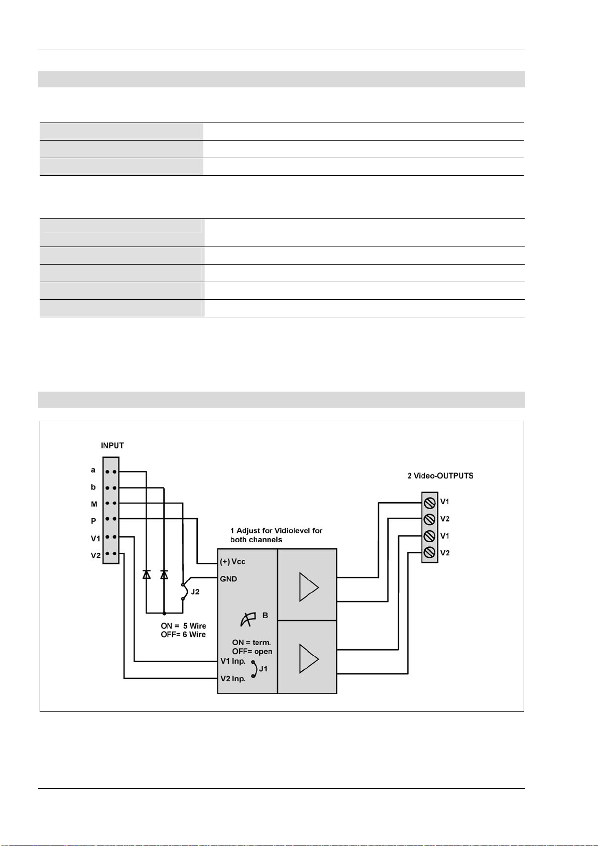
Jumpers
J1 = fitted = horizontal = termination resistor on the input activ
J2 = not fitted = vertical = 6-wire-operating
Configuring
J1: for setup the FVY1200 as terminal device.
Fitted (horizontal, fitted to both upper contacts), the video distributor is instal-
led as the terminal device at the end of a TCS:BUS video line. It activates the
termination resistor at the input.
Not fitted (vertical, to two upper contacts): the video distributor is not installed
as the terminal device at the end of a TCS:BUS video line.
average terminals without assignment
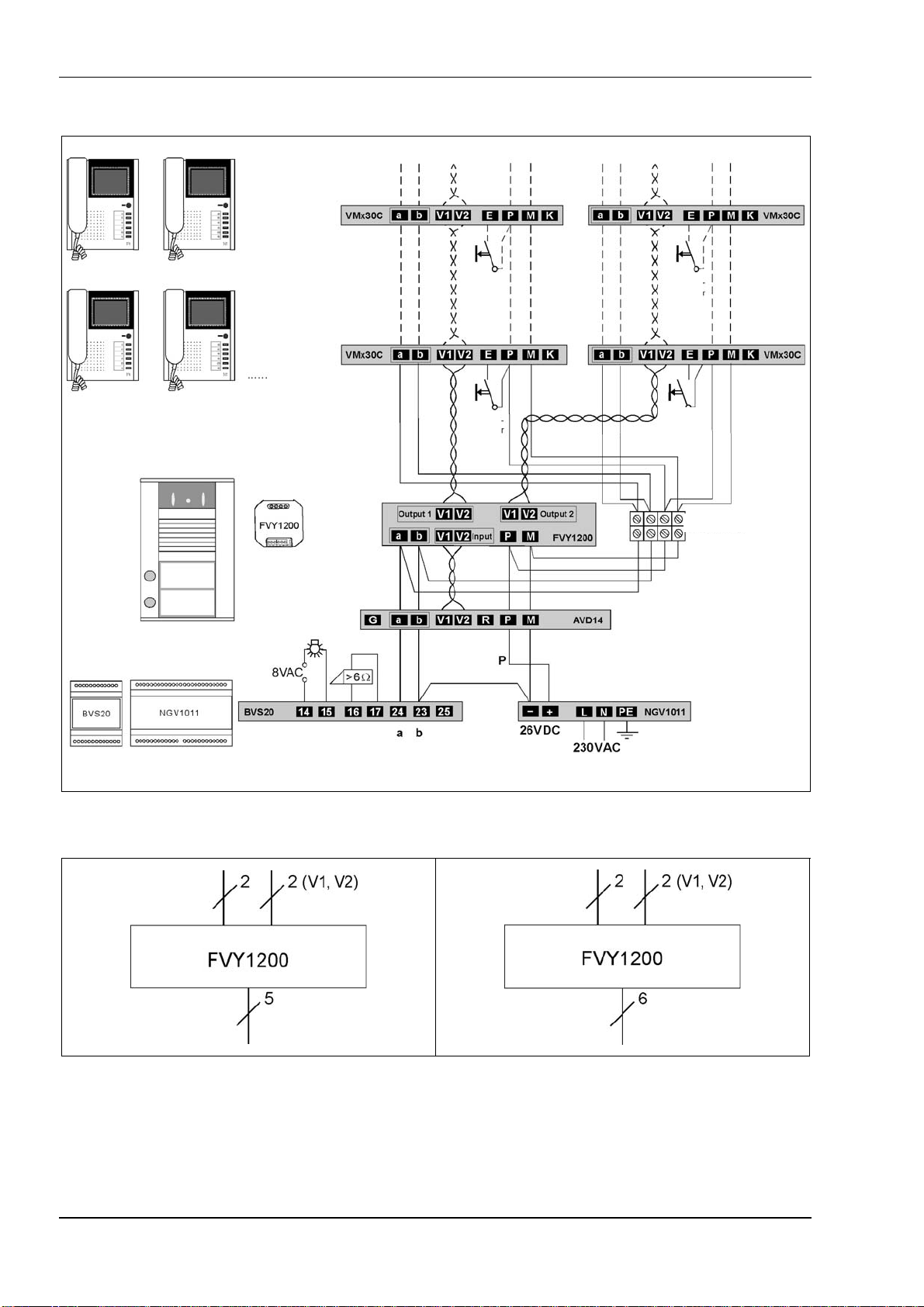
J2: for earth connecton in 5-wire-special operating mode (b – M, divice-
internal).
Fitted (horizontal, fitted to both lower contacts): the video distributor is opera-
ted in a TCS system with 5-wire- special operating mode.
Not fitted (vertical, to two lower contacts): the video distributor is operated in
a TCS system with 6-wire- operating mode.
TCS TürControlSysteme AG •Geschwister-Scholl-Str. 7 •D-39307 Genthin Technische Änderungen vorbehalten.
Tel.: 03933/879910 •FAX: 03933/879911 •www.tcs-germany.de PI_GB_FVY1200-x600_Art0017593_1v0.doc mi