TDE Instruments DPM961 User manual
DPM961 / DPM962
Bedienungsanleitung
Instructions manual
Instructions d'utilisation
Manual de utilizacion
Istruzioni per l'uso
! "
#" ""
$
%
&'
%"(
)
#
*+
*
%
,
$-
$"",
,)"$""
,$".
,$""/
0
1
2
3
0
0
0
0
0
4
4
4
4
4
1 / 16

Abmessungen
Dimensions
Dimensiones
Dimensioni
TD Instruments GmbH
Gewerbestraße 8
D-71144 Steinenbronn
Tel.: +49 7157 20801
Fax: +49 7157 20813
mail: [email protected]
Web: www.tde-instruments.de
2 / 16
5
,"
6/
6/ 7.
6
894
A
B
C
D
E
F
G
H
J
K
L
M
N
O
DPM961
24mm
3,5mm
2,54mm
22mm
48mm
37mm
45mm
14mm
10mm
5mm
2,54mm
3mm
13mm
10mm
DPM962
36mm
9mm
2,54mm
33mm
72mm
61mm
68mm
14mm
10mm
6mm
2,54mm
3mm
18mm
14mm
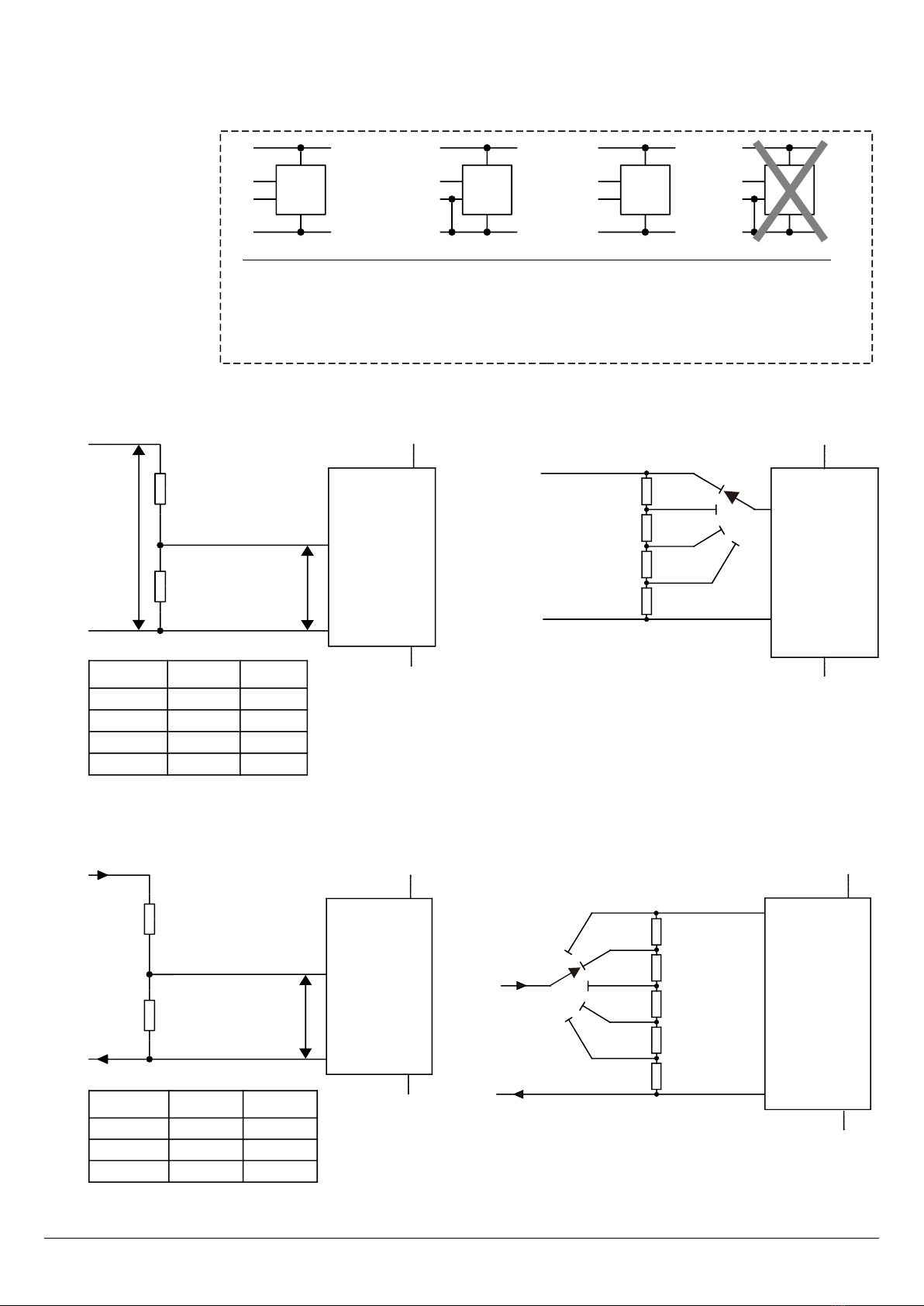
1. Beschreibung
# 0 : ,
$/;< =
&+ >?/9)
+@ 1 3 # , #"
- 9)1#>+
A >" 9
) &
1##"<
- +@<
#" 9
) @
$- - < /
" "9
•$"B
•+ -#
•C
•>"1 3#,
•>?/D3#>E
•=+$/
•$/ B F
//
2. Sicherheitshinweise
$%%&G=) +"F
>## #9$
%B )6G*H )6G=) + "
F > I# 9 ?
C < C/-
- <? />/
GJ$ %
- < CBB - 9
8 "<
*"- 4KG#,9
@F " 4KG#
- < "
- B extern!- 9
3. Technische Daten
Genauigkeit
DI -E<1L
Linearität
I -
Abtastrate
0"+9
Temperaturstabilität
0"":M,
Betriebstemperatur
1M,
Lagertemperatur
2M,
Versorgungsspannung (5-V-Betrieb)
02#,
Versorgungsspannung (9-V-Betrieb)
2#,
Versorgungsstrom
$
Spannung für Hintergrundbeleuchtung
4<11<1#,
Strom für Hintergrundbeleuchtung DPM961
4$
Strom für Hintergrundbeleuchtung DPM962
K$
ingangsimpedanz
N
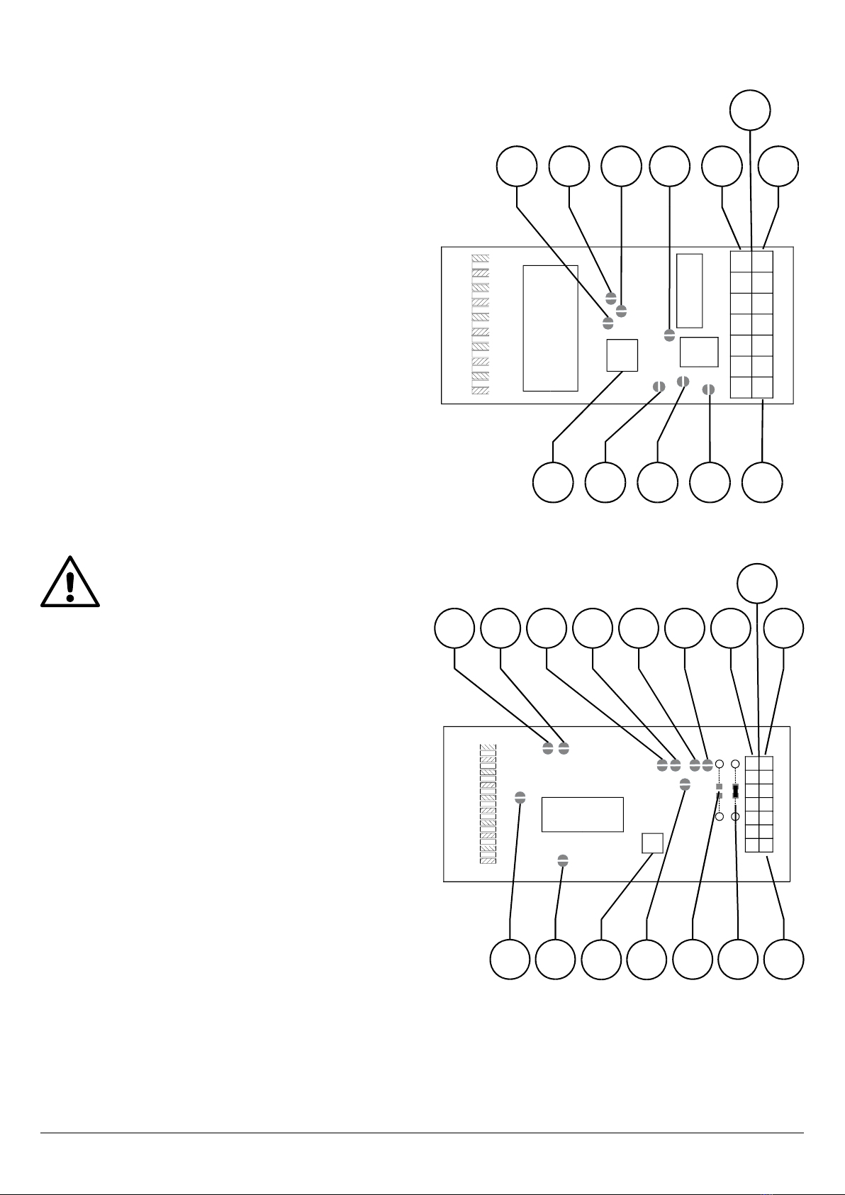
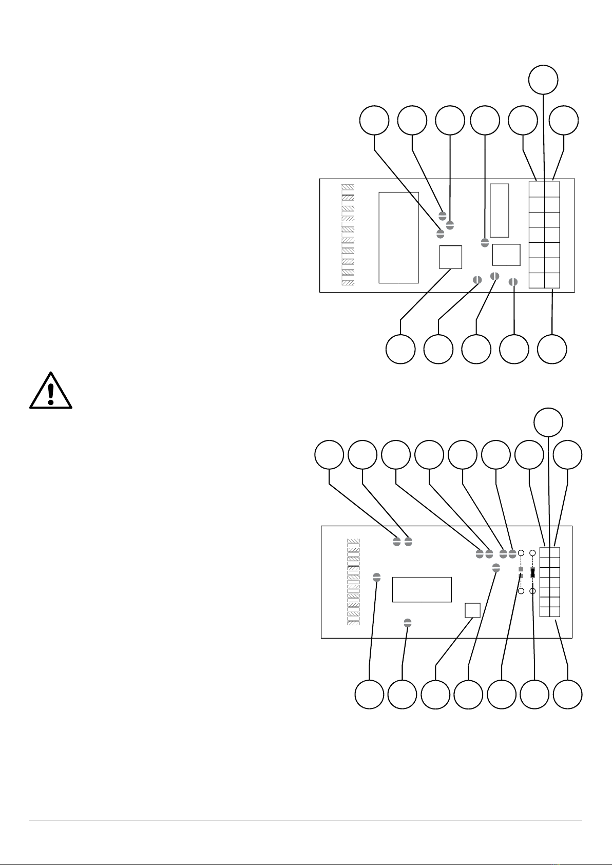
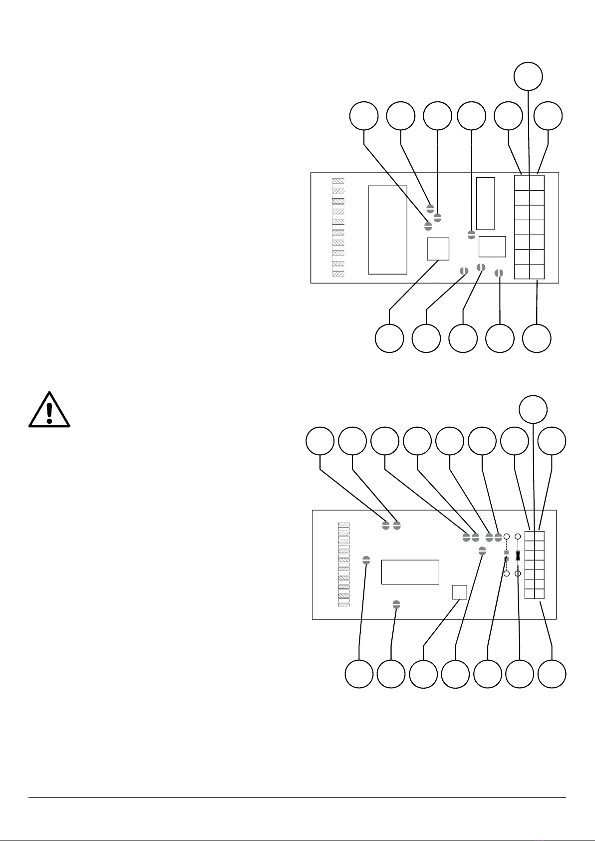
4. Leiterplatte
DPM961
DPM962
3 / 16
$
M,
M&
J
5
O
#
>*5A*52 4
*5*5*51*5P
CN1
$
#
*5=
*54
*5,
$
M,
M&
J
5
O
#
*52*5P*51 4
*5A*5=*54*5,
CN1
#

5. Anschlussbelegung CN1
Pin1
IN HIF"
Pin2
IN LOF
Pin3
VDDC" "<Q1# Q3#
Pin4
VSSC" <#
Pin5
COMMON$C+%
Pin6
BL+= R$Q1#
8? Q3##9
3PRN<<1?S
3PRKN<<1?
Pin7
HOLD $ # / % +
$/-
Pin8
REF HI/""
Pin9
ON (anzeigen)$/"+9
/"+- /9
Pin10
OFF (nicht anzeigen) $ /"+9
/"+- /9
Pin11
BL-6#= 9
=-R+#F<4
Pin12
DP3/"+9333
Pin13
DP2/"+3933
Pin14
DP /"+3393
6. Hinweis
< CB
- < CB 0
9 ? F
CB < /B/
/F@"
- 9
7. Funktionsweise
)6G=)<)6G*H %&G=) /B9
7- "
">//9/
$ 1#
$6$*HCT%G,HH6 #9
/ "
C+/9
/" D%&G=)E -
# 9 "
-+ <G# S +
" 7- $- "
- <"- T+8
? B ++/9
8. Wahl der Versorgungsspannung
+@ 3 1 # , #
" - 9 ) 1#> +
A #"
- 9 ) 1#> 7
>-/+ + - 9
- > -
*5*@+ *"
+9
9. Verbindungen und Modus-Anschlüsse
5-Volt-Betriebsmodus:
*51
*5P 2
9-Volt-Betriebsmodus:
*51
*5P
Verbindung ANALOGU COMMON mit IN LO:
3PRU1,6
3PR*5
Verbindung ANALOGU COMMON mit VSS:
3PR4U1,6
3PR*5
Verbindung R F HI mit VR1 (Verbindung lösen, wenn
externe Referenzspannungsschaltung verwendet
wird):
*54
Verbindung R F LO mit ANALOGU COMMON:
*5,
Verbindung R F LO mit IN HI:
*5=
Batterie-leer-Funktion deaktivieren. Beim 5-V-Betrieb
immer zu deaktivieren:
*52
Testverbindung; Anzeige wird auf 1888 gesetzt.
Höchstens zwei Sekunden lang benutzen, da sonst
Anzeige beschädigt wird!:
*5A+//+
10.Konfiguration
)- /*5*@+
# ,6 7-
$- +9-
$8? B +9
>3P+@ ? B
$ >@- 9&$GN
? < - <
A=A? B @- +@9
&C+<L <L? B
9? C+<
+ # " -
- 9
4 / 16
Siehe Anwendungsschaltungen ab Seite 14
1. Introduction
# 0 : , -
;< - ;
- 9A" -1
3 # , ""; 9 ) 1 # "<
" "
9 ) < -
1# ""; < -
- /
"";
A - ""
< 9
•$";
•#
•*-"-"
•13#,"DE
•*-;-D3#";E
•$
"
•= -
2. Safety instructions
6";+ #G#
# " %&G=)9 6
I# ; " )6G*H )6G=)
"9 ) ;";+
< ;
GJ$-
" ;9
A 8 - ;
,> 4KG#G,9 ?
4KG#<
externally!
3. Specification
Accuracy
I91L
Linearity
I*
Sampling rate
0"
Temperature stability
0"":M,
Operating temperature
1M,
Storage temperature
2M,
Supply voltage (5V mode)
02#,
Supply voltage (9V mode)
2#,
Supply current
$
Backlight voltage
491191#,
Backlight current DPM961
4$
Backlight current DPM962
K$
Input impedance
N
4. PCB
DPM961
DPM962
5 / 16
$
M,
M&
J
5
O
#
>*5A*52 4
*5*5*51*5P
CN1
$
#
*5=
*54
*5,
$
M,
M&
J
5
O
#
*52*5P*51 4
*5A*5=*54*5,
CN1
#

5. Connector CN1
Pin1
IN HI"
Pin2
IN LO6"
Pin3
VDD ,""";Q1G#Q3G#
Pin4
VSS ,"";G#
Pin5
COMMON$"
Pin6
BL+>+RQ1G#-8
Q3G#"";9
3PRN<91?S
3PRKN<91?
Pin7
HOLD,#/ ";
Pin8
REF HI"
Pin9
OND E, ""
Pin10
OFF D6 E, "
"
Pin11
BL- >+ "";9 6R ;
G#"4
Pin12
DP3"9333
Pin13
DP2"3933
Pin14
DP "3393
6. Note
$;
8 09)
<-;
" 9
7. Analogue Inputs and Internal Reference
Voltage
)6=)<)6*H %&=) "9A;
"
-""-"";9A;8"
1# - #
9 A
- "
+- 9
A D%& =)E ;
"#9A;9#
; ""<99
";8-
9
8. Power Supply Selection
A " -13#,"";
9)1#""
"";;9)1#"<-<
-; 9)3#"<
; 9A "
;" *5
" 9
9. Links and Mode Connections
5-Volt-Mode:
*51H"
*5P 2
9-Volt-Mode:
*51
*5PH"
Links ANALOGU COMMON to IN LO:
3PR,,6"U1
3PR *5
Links ANALOGU COMMON to VSS:
3PR,,6"4U1
3PR *5
Links R F HI to VR1 (remove link if using external
reference voltage circuit):
*54
Links R F LO to ANALOGU COMMON:
*5,
Links R F LO to IN HI:
*5=
Disables low battery function. Always disable for 5V
operation:
*52
T ST LINK. Forces display to 1888. Do not use for
more than 2 seconds or damage to the display may
occur:
>; *5A
10.Configuration
A "
"" ; *5 "
" ,69A
; 8 9 ?
3P< ;
"$ >9$O
$<- A=A
9
9L ;
9L9A;8 ;
9
6 / 16
Application Circuits (page 14)

1. Introduction
V ,, "; W 0 :
; X <
X 9
* " Y
X 1 3 ,,9 % 1 <
"
X9 <
"" X
1#<" 8
W X9
*" ""
<
9
•"
•"Z #
•& Z
•A 13,,
•; Z ZD:
"3E
•A8 "
#
•&
2. Instructions de sécurité
$ "#G#
# " Y " W X %&G=)9 $
"I#"Y"
8 )6G*H )6G=)9 %
" <
""" " W GJ$ Y
X< X""
9
* 8 "
"
4KG#G,,9 " W
4KG#< W X
Y W l'extérieur! D"
E[
3. Caractéristiques techniques
Précision (±1 LSD)
I91L
Linéarité
I*
Fréquence des relevés
0"
Stabilité thermique
0"":M,
Température d'opération
1M,
Température de stockage
2M,
Potentiel alimentation (mode 5V)
02#,
Potentiel alimentation (mode 9V)
2#,
Courant alimentation
$
Potentiel retour (voir page suivante, CN1)
491191#,
Courant retour DPM961
4$
Courant retout DPM962
K$
Impédance d'entrée
N
4. Cartes de circuits imprimés
DPM961
DPM962
7 / 16
$
M,
M&
J
5
O
#
>*5A*52 4
*5*5*51*5P
CN1
$
#
*5=
*54
*5,
$
M,
M&
J
5
O
#
*52*5P*51 4
*5A*5=*54*5,
CN1
#

5. Connecteur CN1
Pin1
IN HI% "
Pin2
IN LO%
Pin3
VDD$9"Q1G#Q3G#
Pin4
VSS$9G#
Pin5
COMMON%
Pin6
BL+RWQ1G#
8"3G#9
3PRN<<1?S
3PRKN<<1?
Pin7
HOLDW#"X
Pin8
REF HI% " "
Pin9
ON (Selectionne)
Pin10
OFF (non Selectionne)W
Pin11
BL- $ 9 6 R
WG#"4
Pin12
DP3# 9333
Pin13
DP2# 3933
Pin14
DP # 3393
6. Remarque
* \DE W
"" "8 09 \]
^ " W X8 \<
X "
" 9
7. ntrées analogiques et Tension interne de
référence
* )6 =)< )6 *H %& =)
9%" 8
W Z Z""9
T 8" W
ZW1#<_
#89*"
" Y ; Z
R Z Z " ""
` a9
* D%&=)E"
"#<"3 "
"9*
9#""Z "W
"" "< Z < " 8"<
"Z" 8
Z
Z9
8. Sélection d’alimentation électrique
* "
X 3 1 # ,,9 % 1#<
"
XX9% 1#<<
X X
Y 9*
" " *5
" 9
9. Liaisons et connexions des modes
Mode 5 Volts:
*51
*5Pb2
Mode 9 Volts:
*51
*5P
Relie ANALOGU COMMON à IN LO:
3PR,8,6"1
3PR *5
Relie ANALOGU COMMON à VSS:
3PR,8,6"41
3PR *5
Relie R F HI à VR1 (annuler la liaison en cas
d'utilisation d'un circuit de potentiel de référence
externe):
*54
Relie R F LO à ANALOGU COMMON:
*5,
Relie R F LO à IN HI:
*5=
Désactive fonction batterie basse. Toujours
désactiver pour opération à 5V:
*52
LIAISON T ST. Impose l'affichage de 1888. Ne pas
utiliser plus de 2 secondes pour ne pas endommager
l'affichage:
*5A
10.Configuration
* "
X""" "
*5 8 XY
,69 * " 8
89 $ 3P<
"Y 8"
$>9TO8"$<
Y "
A=A9
" <L< <L
9 " <
"/ "
9
8 / 16
Circuits d'application (page 14)
1. Introducción
#W ,, 0: !
! X < . .
X 9%"
. X. 139%
1<".
W . 9%
<c "" U1#
" (d
9
%" "
< .
.9
•$"
•*" #
•>7
•H".1.3,,
•$ 7!D.".
3E
•$ " !
;"
•
2. Observaciones de seguridad
6;7 #G#;#
" " %&G=)96"
7 I#
)6G*H)6G=)98"
" !<
7 "
GJ$ "
( 9
% 7 e8 " "
8. " 4KG#9
7; 4KG#<
e
externamente!
3. specificación
Precisión
I91L
Linearidad
I*
Velocidad de muestra
0"
stabilidad temperatura
0"":M,
Temperatura de operativa
1M,
Temperatura de almacenamiento
2M,
Voltaje de alimentación (modo 5V)
02#,
Voltaje de alimentación (modo 9V)
2#,
Corriente de alimentación
$
Voltaje de contraluz (ver página siguiente, CN1) 491
191#,
Corriente de contraluz DPM961
4$
Corriente de contraluz DPM962
K$
Impedancia de entrada
N
4. Circuito impreso
DPM961
DPM962
9 / 16
$
M,
M&
J
5
O
#
>*5A*52 4
*5*5*51*5P
CN1
$
#
*5=
*54
*5,
$
M,
M&
J
5
O
#
*52*5P*51 4
*5A*5=*54*5,
CN1
#

5. Conector CN1
Pin1
IN HI% ."
Pin2
IN LO% .
Pin3
VDD. ,,."Q1G#.Q3G#
Pin4
VSS. ,,.G#
Pin5
COMMON% d.
Pin6
BL+,/RQ1G#8"
. Q3G#9
3PRN<91?S
3PRKN<91?
Pin7
HOLD,#""
Pin8
REF HI% 7 "
Pin9
ON D E , "
Pin10
OFFD E,
"
Pin11
BL- ,/ . 9 6
G#4
Pin12
DP3/"+ 9333
Pin13
DP2 3933
Pin14
DP 3393
6. Nota
, (
8 09
( <
". 9
7. ntradas analógicas y Voltaje de
referencia interno
)6=)<)6*H;%&=) 9
" 7 ;7
.9*d8".
1# d . ; #
79%8! 7"
;
d9
%7 D%&=)E7 "
". # " ; ".9 % 7
7 e < # " " 7
" " " < 79 "
"". 8
/ 9
8. Selección de suministro de energía
%c " ". X. 3
1#,,%1#W
". . 9
A8<1#<. X!
X 9%". 3#<"
9 %
7X7'" *5
" " c 9
9. nlaces y conexiones de modo
Modo 5 voltios:
*51
*5P;2
Modo 9 voltios:
*51
*5P
nlace ANALOGU COMMON a IN LO:
3PR,,671
3PR *5
nlaces ANALOGU COMMON a VSS:
3PR,,6741
3PR *5
nlaces R F HI a VR1 (retire enlace si utiliza un
circuito de voltaje de referencia externo):
*54
nlaces R F LO a ANALOGU COMMON:
*5,
nlaces R F LO a IN HI:
*5=
Desactiva función batería baja. Siempre desactivada
para operación de 5V:
*52
NLAC PRU BA. Pone la pantalla en 1888. No lo
utilice durante más de 2 segundos o se pueden
producir daños a la pantalla:
>"*5A
10.Configuración
* "
"." "
*5;8 7/ 7
,69 % .
89 , 3P<
" "
$;>9 O"
$< "
A=A9
<L "
". <L9%8"
".9
10 / 16
Circuitos de aplicación (página 14)

1. Introduzione
# ,, 0 :
</
9 C "
/ /,, 13
96/1<
"/ /
/9 ) < ""
/1#<
"
/9
C ""/
/ < /
// 9
•)"/ "W
•*"#
•>
•&/13,$D/
E
•"D W3E
• " W
"
•&/
2. Istruzioni di sicurezza
$X%&G=)""
X#G##96
X I# "c
")6G*H)6G=)9Z"W
<
"""
Z" " GJ$<
" ZW9
* "
,> 4KG#9
4KG#<
esternamente!
3. Specifiche
Precisione
I91L
Linerità
I*
Velocità di campionamento
0
Stabilità temperatura
0"":M,
Temperatura di funzionamento
1M,
Temperatura di conservazione
2M,
Tensione di alimentazione (modalità 5V)
02#,
Tensione di alimentazione (modalità 9V)
2#,
Corrente di alimentazione
$
Tensione di retroilluminazione
491191#,
Corrente di retroilluminazione DPM961
4$
Corrente di retroilluminazione DPM962
K$
Impedenza di ingresso
N
4. PCB
DPM961
DPM962
11 / 16
$
M,
M&
J
5
O
#
>*5A*52 4
*5*5*51*5P
CN1
$
#
*5=
*54
*5,
$
M,
M&
J
5
O
#
*52*5P*51 4
*5A*5=*54*5,
CN1
#

5. Connettore CN1
Pin1
IN HI)" /"
Pin2
IN LO)" /
Pin3
VDD$/" ,$Q1G#Q3G#
Pin4
VSS$/ ,$G#
Pin5
COMMON)"
Pin6
BL+ /R,Q1G#""
"/Q3G#9
3PRN<<1?S
3PRKN<<1?
Pin7
HOLD,#" ";
Pin8
REF HI)""
Pin9
ON (selezionato),""
Pin10
OFF (non selezionato) , " "
//
Pin11
BL- $/ / 9 6R
G#4
Pin12
DP3 9333
Pin13
DP2 3933
Pin14
DP 3393
6. Nota
H "
"" 09
"X <
" "/ /9
7. Input analogici e Tensione di riferimento
interno
)6=)<)6*H %&=) " /
"
Z9*Z/
W1# #
9 6
// " /<
Z W9
* D%& =)E
" "/ #9 *
" <G#<"
" ""/< " "
" Z"
Z// / "/9
8. Selezione alimentazione
) " /
/ 31#,,96/1#
"/ /
/9 6 / 1 #<
</
9 * W "
" *5"
" 9
9. Collegamenti e modalità di connessione
Modalità 5 volt:
*51"
*5P2
Modalità 9 volt:
*51
*5P"
Connessione ANALOGU COMMON con IN LO:
3PR"1 ,6
3PR*5
Connessione ANALOGU COMMON con VSS:
3PR"41 ,6
3PR*5
Collegare R F HI a VR1 (scollegare se si utilizza una
tensione di riferimento esterna):
*54
Collegare R F LO a ANALOGU COMMON:
*5,
Collegare R F LO a IN HI:
*5=
Disabilita la funzione di batteria scarica. Disattiva
sempre per il funzionamento a 5 V:
*52
Test di composto; L'annuncio è impostato su 1888.
Utilizzare per un massimo di due secondi, altrimenti il
display sarà danneggiato!:
*5A""
10.Configurazione
C " "
""/ " " *5
"X/ ",69)"
9,
3P< "
"/$>9T
O"$< "
/A=A" 9
*" <L <L9
"<"
/9
12 / 16
Circuiti applicativi (Pagina 14)

Verbindungen
Links
Liaisons
nlaces
Collegamenti
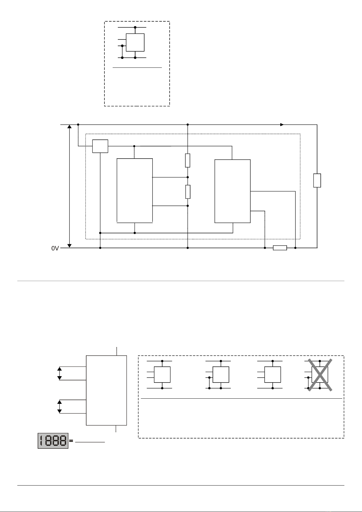
Konfiguration Anzeigesymbole
Configuration Annunciator
Configuration de Tableaux indicateurs
Configuración de Avisadores
Configurazione di Segnalatori
Konfiguration Dezimalpunkt
Configuration Decimal Point
Configuration Virgule Décimale
Configuración Punto Decimal
Configurazione Punto Decimale
13 / 16
f0
,6
0
H&&
3
4
0
f
Ω
f#
$
#
5
ΩΩ
JJ
M&
M&
M,
M,
$
#
5
H&&
H6
3P 3P
$
)6=)
>
&
µC
)6*H
*5
,H
+
*5 *5, *5=
%&=)
*54
#
#
*51 *5P
1#
>*Q
>*−
%&*H
=H*
*52
B//"
#
" "
7 ".
"
Anwendungsschaltungen, Application Circuits, Circuits Intégrés pour les Applications,
Circuitos De Aplicación, Circuiti Di Applicazione
Spannung / Strom
Voltage / Current
Tension / Courant
Voltaje / Corriente
Tensione / Corrente
14 / 16
DPM961 DPM962 DPM961 DPM962 DPM961/962 DPM961/962
,6R4Q1
*54
*5P
*52
*5,
*5
*54
*5P
*52
*5,
,6RQ1
,6R4Q1
*54
*5P
*52
*5,
*5
*5
*54
*5P
*52
*5,
*54
*51
*5,
#
#f1#
)6*H
)6=)
)6
#
#f1#
)6*H
)6=)
#
#f3#
)6*H
)6=)
#
#f3#
)6*H
)6=)
Q#
#
)6=)
)6*H
359L ?g
359L ?g
359L ?g
59L ?g
#
#
#
#
0
4
#
#
Q#
#
)6=)
)6*H
0
4
#
#
Th
I#
%iA
%iA
T%iA
T%iA %iA %iA
# N j
# 3+ +
# 33+ +
# 333+ +
%iA0
$
$
$
$
3
Ω
g?
3
Ω
g?
3
Ω
g?
93
Ω
g?
9
Ω
k?
J$
Q#
Q#
#
#
)6=)
)6=)
)6*H
)6*H
0
0
4
4
#
#
#
#
I
*
*
,
,
,
Th
I#
I
I%iA0 l
$ N 94?
$ 9N 94?
$ 9N 4?
Spannung und Strom
Voltage and Current
Tension et Courant
Voltaje y Corriente
Tensione e Corrente
Spannungsverhältnisse
Voltage Ratio
Tension Proportionnelle
Relación de Voltaje
Rapporto di Tensione
15 / 16
Q#
T
#
)6=)
%&=)
)6*H
,HH6
K
1
0
4
#
#
T8
T
DPM961 DPM962 DPM961 DPM962 DPM961/962 DPM961/962
,6R4Q1
*5P
*52
*5,
*5
*5P
*52
*5,
,6RQ1
,6R4Q1
*5P
*52
*5,
*5
*5
*5P
*52
*5,
*51
*5,
#
#f1#
)6*H
)6=)
)6
#
#f1#
)6*H
)6=)
#
#f3#
)6*H
)6=)
#
#f3#
)6*H
)6=)
T T T
#hTh#
T
#hTh#
DPM961 DPM962
,6RQ1
,6R4Q1
*54
*5P
*52
*5,
*5
*5
*54
*5P
*52
*5,
#
#f1#
)6*H
)6=)
%iA0
h
I#
)6=)
)6=)
T
%iA
)6*H )6*H
# #
# #
I
*
*
,
,
,
%iA
%iA
h
I#
Q1#

Widerstand
Resistance
Résistance
Resistencia
Resistenza
Temperatur mit Thermoelement
Temperature using a Thermocouple
Température à l’aide d’une Thermocouple
Temperatura con un Térmico
Temperatura Utilizzando un Coppia Termoelettrica
16 / 16
0
#
#
4
)6=)
)6*H
335
5
0
2
4
4
K
3
$131
1PΩ
*%
&
#
A;"5
DPM961 DPM962
,6RQ1
,6R4Q1
*54
*5P
*52
*5,
*5
*5
*54
*5P
*52
*5,
#
#f1#
)6*H
)6=)
Q1#
Q#
Q#
#
)6=)
%&=)
)6*H
K
0
4
#
#
DPM961 DPM962
,6RQ1
,6R4Q1
*5P
*52
*5=
*5
*5
*5P
*52
*5=
#
#f1#
)6*H
)6=)
%iA
%iA
1+
%iA
%iA
; *,
N N N9N
+ + N N
+ + +N 9+N
+ + +N 9+N
0 N 9N
T8
T
644K
T
T
Q1#
Other manuals for DPM961
1
This manual suits for next models
3
Table of contents
Languages:
Other TDE Instruments Multimeter manuals


