TDI TurboTwin T30-M User manual

AN09-484 From Tech Development
6800 Poe Ave. Dayton OH 45414
Tel: (937) 898-9600 Fax: (937) 898-8431
Website: www.tdi-turbotwin.com
Publication: T3-790, Rev. 2
Issued: January 9, 2013
INSTALLATION AND OPERATING
MANUAL
TURBOTWIN™Model: T30-M
Auxiliary Lube Pump Air Motors

TDI TURBOTWIN™
FROM TECH DEVELOPMENT
Publication: T3-790, Rev. 2
Issued: January 9, 2013 Page 1
TABLE OFCONTENTS
SECTION SUBJECT PAGE
1.0 General Information …. ………………………………………………………. 2
1.1 Description & Advantages ... ………………………………………………… 2
1.2 Basic Operation ...……………………………………………………………… 2
1.3 Product Identification ...………………………………………………………. 3
1.4 Motor Performance & Output ….……………………………………………... 3
2.0 Installing the Motor …………………………………………………………… 5
2.1 Proper Installation and Setup ….…………………………………………….. 5
2.2 Supply & Exhaust Line Installation ……..…………………………………… 5
2.3 Motor Controls ………………………………………………………………… 6
2.4 Inlet Pressure Check Port. ……………………………………………………. 6
2.5 Matching Motor Output to Load ………………………………………………. 7
2.6 Adjusting Motor Output Speed ...…………………………………………….8
3.0 Motor Operation ……………………………………………………………….. 7
4.0 Trouble Shooting Guide ………………………………………………………. 8
5.0 TURBOTWIN Warranty ………………………………………………………….. 9
FIGURES ILLUSTRATIONS PAGE
1 T30-M Lube Pump Motor ........................................................................... 10
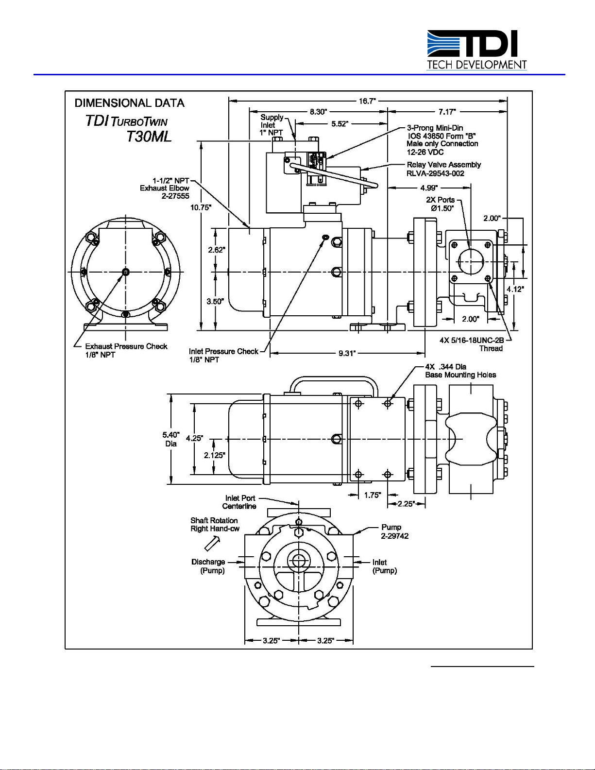
2 T30-M Lube Pump Motor w/Integral Relay Valve (Pneumatic) …………… 11
3 T30-M Lube Pump Motor w/Integral Relay Valve (Solenoid) ………………12
4 T30-M Lube Pump Motor w/Modified NEMA 56C Mounting Flange ………13
5 T30-M Lube Pump Motor w/ NEMA 56C Mounting Flange ………………...14

TDI TURBOTWIN™
FROM TECH DEVELOPMENT
Page 2 Publication: T3-790, Rev. 2
Issued January 9, 2013
1.0 GENERAL INFORMATION
This manual contains Instructions for installation,
operation and maintenance of TDI TURBOTWIN™
Model T30-M Air Motors used as auxiliary drives for
Pre & Post Lube Oil Pumps. These are supplied by
OEMs and can also be obtained in the aftermarket as
motor upgrades.
Review this manual before installing or operating T30-
M Air Motors. For Questions, ContactyourAuthorized
TDI Distributor, OEM or TDI directly.
WARNINGS, CAUTIONS AND NOTES
Certain types of information are highlighted in this
manual for your attention:
WARNINGS: - used wherein NON-
COMPLIANCE will likely result in injury to
personnel or damage to the equipment.
CAUTIONS: - used where there is possibility
of damage to the equipment.
NOTES/IMPORTANT: - used to cite special
information for “optimum” use & care.
1.1 DESCRIPTION & ADVANTAGES
T30-M Air Motors are similar to the design used in T30
AirStarters. T30-M featuresvariousinterfacesallowing
the motors to be fitted with couplings or directly to
different model mechanical (oil) pumps. T30-M Air
Motors are superior to other types of drive motors in:
oDurability- Very tolerant of contamination
(liquid or fine solids) in the air/gas supply.
oCost Effectiveness – costly supply air/gas
filtration, drying, lubrication are generally not
required.
oEfficiency - Low air/gas consumption per
unit of power produced.
oCooler Running – greater expansion allows
motor to run cooler on extended duty cycles.
oApplication Flexibility – Variable operation
(output power & RPM). Suitability for use at
much lower air/gas supplies to 10 psig.
oOwnership Cost - Sealed bearings and
gear train require no maintenance or
external lubrication.
oEase of Compliance - Exhaust is cleaner,
since motor produces no (fugitive) oily mist
emissions.
NOTE
THIS MOTOR IS TO BE SERVICED ONLY BY AUTHORIZED TDI
TURBOTWIN™ DISTRIBUTORS, DEALERS, AND REPAIR
CENTERS. DO NOT OPERATE THIS MOTOR UNLESS IT IS
PROPERLY ATTACHED TO AN ENGINE.
oTURBOTWIN T30-M Air Motors are designed
for operation on either compressed air or
natural gas.
oTURBOTWIN T30-M Air Motor materials are
compatible with “sour” natural gas and marine
environments.
oTURBOTWIN T30-M Air Motors are ATEX
certified (where indicated in certain OEM
applications).
oTURBOTWIN Air Motors do NOT require mist-
type or injection-type lubrication of the air/gas
supply. These are not fitted on OEM
applications and should be removed when
upgrading from vane-type air motors.
NOTE
Throughout this manual, the term “air” designates the
Motor drive medium. Unless otherwise stated, "air"
means either compressed air or natural gas. UNITS
WITH INTEGRATED CONTROLS as SUPPLIED BY
TDI, ARE NOT OPERABLE ON NATURAL GAS.
OEM applications, may be supplied with gas
compatible controls, and which meet various
agency requirements as specified.
1.2 BASIC OPERATION
NOTE
T30-M Air Motors are designed for intermittent duty
cycles, NOT continuous duty cycles.
TURBOTWIN T30-M Air Motors are two-stage turbine
driven, gear reduced air motors, with the following key
differencesvs. other typesofmotorscommonly usedin
similar (pump) drive applications:
Unlike electric Motors, power output and
operating speed can vary greatly depending
on the dynamic operating pressures supplied
to the motor inlet and the loads imposed.
(See performance data).
Unlike vane-type (positive displacement) or
electric motors, turbine-type air motors, if
unloaded/under-loaded, will operate at much
higher free-speeds (or over-speed).
Turbine type motors should be properly
selectedand regulatedto operate efficiently at
a required load & speed… rather than over a

TDI TURBOTWIN™
FROM TECH DEVELOPMENT
Publication: T3-790, Rev. 2
Issued: January 9, 2013 Page 3
wide range of inlet supply pressures, loads &
speeds.
BASIC OPERATION:
Pressurized air or natural gasenters themotor through
the inlet port. Air/gas expands through the two-stage
turbine and is exhausted to atmosphere. The turbine
drives through a gearbox (speed reduction) to the
output shaft. Indicated motor output (torque, HP,
RPM) is as measured at the shaft end.
Motor rotation is indicated “as viewed” on theshaft end
of the motor; as either RH-CW (clockwise) & LH-CCW
(counter-clockwise).
IMPORTANT
To attain maximum product life, it is important to
properly match the Motor inlet supply pressure,
power output and Motor speed to a specific load.
Regulate (if necessary) Motor supply air
pressure to the lowest possible setting
required to drive the load (pump). No more.
There are two pressure check ports on the
Motors (at inlet & exhaust) that allow users to
check the dynamic inlet supply pressure &
exhaust (back) pressure applied to the Motor.
Motor exhaust back pressure exceeding 10
psig may reduce the life of the Motors’ rear
seals & bearings.
Dynamic pressures aremeasured while Motor
is running at indicated pressure check ports
(inlet & exhaust) on the Motor housings.
1.3PRODUCT IDENTIFICATION
The identification nameplate(s) attached to Motor
housing should indicate the following information:
Model Designation - T30-M
P/Ns (OEM &/or aftermarket p/ns) may be
present on the Motor data tag(s).
Serial Number (date manufactured code)
Maximum Operating (Inlet) Supply Pressure
Direction of Rotation
NOTE
Direction of Rotation - either left hand LH (CCW) or
right hand RH (CW) is designated from output shaft
end of the Motor.
CAUTION
Exceeding the Maximum Operating Pressure rating
shown on Motor nameplate or continued operation
above the Recommended RPM Range (speed)
indicated may result in damage to the Motor or
damage to the driven equipment (pump).
NOTE
Maximum Operating Pressure as indicated on the
nameplate can be verified at the pressure check port
below Motor inlet port, and set dynamically as
described in Section 1.2.
IMPORTANT
DO NOT RUN UNLOADED or UNDERLOADED
Optimum (correct) Operating Supply Pressure is not
necessarily the Motor supply pressure observed in
your application or the Max rated Operating Pressure.
Motor supply pressure optimization, per application,
has been proven to maximize the service life and
reliability of the Motor(s) in most applications.
NOTE
TheProof Pressureshownon thenameplateindicates
the maximum static pressure rating at which Motor
turbine Motor housing(s) will not burst in operation.
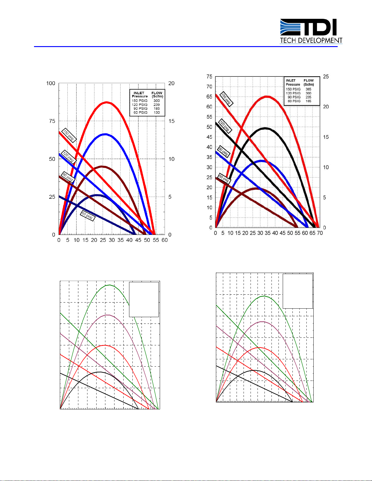
1.4MOTOR OUTPUT AND
PERFORMANCE
Please refer to Performance Graphs which illustrate:
Motor Output (shaft HP/Torque) over a range
of dynamic supply pressures & at speeds
(RPM) from stall to maximum free speed is
indicated on the performance graphs of each
Motor model.
Air Consumption Rates over a range of
dynamic supply pressures (consumption is
constant at a given dynamic inlet pressure)
and is therefore cited in a separate table on
the Performance Graphs for a Motor model.
Operating speed varies by approximately
+25% when motor is run on methane gas.
Supply pressure should be adjusted
accordingly to prevent excessive Motor/pump
speed (over-speed) on gas.
Performance assumes exhaust is to
atmosphere or where Motor exhaust system
piping minimizes back pressure, to less
than 10 psig.
TDI TURBOTWIN™
FROM TECH DEVELOPMENT
Page 4 Publication: T3-790, Rev. 2
Issued January 9, 2013
T303-M Performance Curve
(Compressed Air)
Output Speed (shaft)/100
Output Speed (Shaft)/100
T303-M Performance Curve
(Methane Gas)
Output Speed (shaft)/100
Output Speed (Shaft)/100
Power
(
HP
)
Power
(
HP
)
Tor
q
ue
(
lb.ft
)
0
5
10
15
20
25
30
0 5 10 15 20 25 30 35 40 45 50 55
0.0
1.0
2.0
3.0
4.0
5.0
6.0
Inlet Flow
Pressure SCFM Nm3/Hr
150 Psig 100 170
120 Psig 80 135
90 Psig 62 105
60 Psig 43 74
150 Psig
120 Psig
90 Psig
60 Psig
0
5
10
15
2
0
2
5
3
0
0 5 10 15 20 25 30 35 40 45 50 55 60 65 70
BFT
0.0
1.5
3.0
4.5
6.0
7.5
9.0
150 Psig
120 Psig
90 Psig
60 Psig
Inlet Flow
Pressure SCFM Nm3/Hr
150 Psig 122 207
120 Psig 100 170
90 Psig 78 133
60 Psig 55 94
T301-M Performance Curve
(Methane Gas)
T301-M Performance Curve
(
Compressed Air
)
Torque
(lb.ft)
Torque (lb.ft)
Power
(
HP
)
Tor
q
ue
(
lb.ft
)
Power
(
HP
)

TDI TURBOTWIN™
FROM TECH DEVELOPMENT
Publication: T3-790, Rev. 2
Issued: January 9, 2013 Page 5
2.0 INSTALLING THE MOTOR
TDI T30-M Motors feature a turbine type air
Motor that does not require lubrication in the
supply air.
If a vane-type Motor is being replaced by a
TDI turbine type Motor, TDI recommends
removal of in-line or mist type lubricators to
minimize Motor supply flow restriction,
eliminate oily exhaust residue and reduce
maintenance.
2.1 PROPER INSTALLATION & SET-UP
WARNING
Do not operate this Motor unless it is properly
connected to a load (see below).
Motor & oil pump must be installed in a
location that prevents unloaded or under-
loaded operation.
T30-M Lube Pump Motor w/optional exhaust muffler
There are two main causes for the oil pump to become
unloaded or under-loaded:
1) Cavitation - air in the oil suction line to the pump.
This can be prevented by insuring the oil supply
(suction) line to the pump inlet, is below the oil sump
level of the equipment/engine. This is referred to as a
“flooded” location, as it insures oil will always be
present at the pumps suction port. This is VERY
IMPORTANT when up-fitting aTDIpumppackage that
uses the T30-M motor, or installing a T30-M motor
replacement on an existing oil pump. Take steps
necessary to prevent accumulation of excessive air in
the oil system. Utilize check valves and vent lines in
accordance with equipment/engine manufacturer’s
guidelines.
2) Excessive Motor Output
Excessive Motor (Horsepower) results in pump over-
speed. Excessive HP output will drive the mechanical
oil pump to a speed higher than recommended (most
are rated at 1200-1750 RPM for maximum life).
Oil pump over-speed does not always produce
excessive or higher (indicated) oil pressures (on a
panel or gauge) because most machines and/or oil
pumps have a pressure bypass. Even pumps with a
pressure bypass, if operated at excessive speed, may
fail bearings and/or seals prematurely.
AdjustingT30-M Motoroutputis accomplishedsimply
by reducing (or increasing if needed) the dynamic
motor supply air/gas pressure. Matching the motor
output speed to the same optimum range as that ofthe
oilpump (1200-1750RPM)will provide maximumT30-
M Motor life
2.2 SUPPLY & EXHAUST LINE
INSTALLATION
WARNING
Be sure to either bleed the pressurized air reservoir
and/or safety the system such as closing all air/gas
supply valves prior to installing Motor or a new
supply line.
The T30-M Motors come standard with a 1.0 inch NPT
female pipe thread connection at the inlet. A 1.5 inch
or 2.0” exhaust adapter is standard.Supplied adapters
are sealed with Viton O-rings.
The Motor supply line consists of the line from the
air/gas supply source (via a pressure regulator when
necessary) through filters, manual and/or automatic
relay valves to the Motor inlet.
The exhaust line consists of the line from the Motor
exhaust to a “safe” location. Turbine exhaust (gas) is
typically plumbed away from the engine area.
Hard piping may be used on supply/exhaust lines. A
section of flexible tubing (gas approved where
required) is recommended, between Motor
inlet/exhaust outlets, to the hard piping. This can
prevent leaks or “wobble” out due to piping weight &
vibrationand ease offieldmaintenance/replacementof

TDI TURBOTWIN™
FROM TECH DEVELOPMENT
Page 6 Publication: T3-790, Rev. 2
Issued January 9, 2013
the Motor(s).
Motor supply & exhaust lines and components should
be dry-fitted for proper alignment /location prior to final
assembly.
All pipe threaded joints should be sealed with Loctite
Pipe Thread Sealant (TDI P/N 9-94085) or equivalent,
for leak tight joints prior to final assembly. Be sure to
tighten all joints to proper torque after final assembly.
The installation of the Motorusing naturalgas issimilar
to the air installation except all fittings, piping, valves
and regulators must be compatible with natural gas
and gas industry regulations.
WARNING
When using natural (or combustible) supply gas
(e.g.methane gas)mustbe pipedtoa safelocation,
routed and terminated according to industry codes
and local regulations.
NOTE
On low pressure applications, if the supply line is
longer than 40 feet, piping size may need to be
increased to minimize dynamic flow losses through
piping and ensure specified output. Similarly, exhaust
piping length & diameter must not induce back
pressure above 10 psig
On higher supply pressures, a regulator or manual
valve may be used to limit dynamic operatingand drive
motor speed (RPM). See Motor Performance Chart
WARNING
Be sure that any/all piping &/or tubing used, meets
applicable requirements and that no leaks are
present following line installation or thereafter.
CAUTION
There is often weld slag, grindings, thread shavings,
hardened compounds and other heavy debris in new
packagepiping &atnew siteinstallations. Therefore,
atcommissioning TDIrecommendsa purgeor“blow-
down” of Motor supply lines to prevent damage to the
Motor. While T30-M TURBOTWIN Motors are highly
tolerant of moisture & fine contamination, Motor life
can be increased by use of a coarse #40 mesh
strainer upstream in the motor supply line
NOTE
Expensive moisture abatement (air/gas drying) is not
required, as this has no effect on the Motors.
2.3 MOTOR CONTROLS
Preferred Motor supply control valve isa pilot-operated
type,which ispneumaticallyor electricallyactuated. A
manual valve may also be used.
CAUTION
SET UP – Motor supply pressure “matching” will
control motor speed and is recommended on all
installations of the T30-M. Do Not use Motor’s (data
plate)Max Operating Pressure rating as the default
supply pressure setting. (also See Section 2.5)
Motor supply pressure (flow restriction) or a pressure
regulator is required:
Where Motor supply pressure exceeds
dynamicMotor operatingpressure(measured
at the inlet port while motor is running. (Over-
pressure).
Where “default” Motor supply pressure (e.g.
engine fuel gas pressure or starting pressure)
producesMotor outputspeedsbeyondwhat is
specified for the application. (Over-speed).
Where motor over-speed, occurs even when
Motor is operated (dynamically) at a pressure
below the Motor’s Maximum Operating Max.
Over-pressure & Over-speed reduce life of Motor &
driven equip (oil pump) & wastes supply air/gas
(increases operating costs).
2.4 INLET PRESSURE CHECK PORT
(checking dynamic operating pressures)
A 1/8" NPT port is located on the Motor housing, at
the air inlet. This port is used to check the dynamic
supply pressure (at the Motor when the Motor is
operating). To check dynamic pressure, remove the
1/8" NPT pipe plug and save for later use. Install a
pressure gauge to read at this port. Using Loctite Pipe
Thread Sealant or equivalent, replace 1/8” NPT pipe
plug upon completion of pressure check.
This pressure monitoring gauge may also be
permanently installed. Alternately, a pressure
transducer may be installed at the pressure check port
and electrical lines routed to a digital display or panel

TDI TURBOTWIN™
FROM TECH DEVELOPMENT
Publication: T3-790, Rev. 2
Issued: January 9, 2013 Page 7
at the operator's station.
2.5 MATCHING MOTOR OUTPUT (SPEED)
TO LOAD – OIL PUMP/MOTOR LOCATION
It is recommended T30-M Motors be installed to
operate at an RPM between 1200-1750 RPM.
Where possible, a hand held tachometer
should be used to double-check Motor/pump
output speeds.
Motor supply pressure should be set at the
minimum pressure required to insure the
Motor runs the speed/load required by the
pump application.
Depending on where indicated/monitored, oil
pressure may not indicate excessive motor
speed since an oil bypass (relief valve) may
reduce this to a indicate a “normal” oil
pressure reading by the operator.
Oil Pump discharge pressure (taken at the oil
pump discharge port) is the best indicator of
pump speed. Followthepumpmanufacturer’s
recommendations.
Do not apply or select the maximum Motor supply
pressure by default, (e.g. “same as” fuel gas pressure
or starting air pressure on the package). Motor speed
& output must account for:
Varying starting or fuel gas pressures.
Varying oil pump models, oil viscosity, oil
temperatures (loads).
Varying site conditions (temperatures, etc…).
Varying oil pressure & cycle times required.
2.6 ADJUSTING MOTOR OUTPUT SPEED
Set multi-meter to measure frequency (Hz).
Connect the two multi-meter leads to the
speed pick-up connector attached to the air
motor.
To identify the speed on the multi-meter,
multiply the frequency times 3 as shown on
the tag affixed to the air motor.
Apply the supply pressure to the motor and
slowly increase the pressure until the desired
output speed is achieved. DO NOT EXCEED
1750 RPM.
NOTE
Motor over-speed: Where motor & pump output
pressure or RPM, exceed that needed for an
application:
Reducing Motor supply pressure;
or
Increasing size of oil pump supply/discharge lines,
will correct this condition.
3.0 MOTOR OPERATION
WARNING
Do not operate the TDI TURBOTWIN Motor at
dynamic supply pressures greaterthan the pressure
rating on the nameplate. This dynamic pressure is
measured at Motor inlet while Motor is running.
Static (non-flowing) supply pressure will
always behigher than theoperating(dynamic)
pressure. The maximum pressure limit (proof
pressure) that the TDI TURBOTWIN Motor
housings may be subjected to is 600 PSIG
(42 BAR).
Where system static pressuremay exceedthe
600 PSIG (42 BAR) limit, in addition to
pressure reducing device, a pressure relief
valve (set below 600 PSIG [42 BAR], should
be used.
Speed Pick-up
Connector
TDI TURBOTWIN™
FROM TECH DEVELOPMENT
Page 8 Publication: T3-790, Rev. 2
Issued January 9, 2013
4.0 TROUBLESHOOTING CHART
TROUBLE PROBABLE CAUSE
SOLUTION
1. Motor does not run;
small air flow from
exhaust.
A. Y-Strainer or filter in supply line
clogged. A. Clean strainer.
B. Nozzle blockage. B. Remove blockage or obstruction from nozzles.
2. Motor does not run;
(rotate) but normal air
flow from exhaust.
A. Broken/damaged turbine
rotor(s). A. Replace all damaged parts.
B. Broken gear train. B. Repair or replace gear train.
C. Seized Load (e.g. oil pump) C. Repair or replace pump (or driven device)
3. Reduced Motor
output power (will not
carry load).
A. Motor inlet air pressure/flow
insufficient to produce required
Motor output.
A. Check dynamic operating pressure at Motor inlet.
Increase air pressure in 10 PSIG increments; DO
NOT EXCEED OPERATING LIMIT.
B. Damaged turbine nozzle. B. Replace turbine nozzle.
C. Inlet supply piping or
components too small. C. Check dynamic operating pressure at Motor inlet.
Supply piping size (lengths/diameters) must match
dynamic flow requirements.
D. Pressure regulator orifice too
small. D. Check dynamic operating pressure at Motor inlet.
Increase orifice size or replace pressure regulator to
one that matches pressure/flow requirements.
E. Inlet supply line valve (ball,
gate, relay, plug) too small. E. Check dynamic operating pressure at Motor inlet.
Install valve that matches flow/pressure
requirements for application.
F. In line lubricator installed in
supply line restricting flow. F. Check dynamic operating pressure at Motor inlet.
Remove lubricator.
G. Control Valve or Regulator not
fully open. G. Check dynamic operating pressure at Motor inlet.
Repair or replace control valve or regulator as
needed.
H. Excessive back pressure;
exhaust restricted. H. Check dynamic operating pressure at Motor
exhaust port. Clean exhaust piping or increase size
to length/diameter required for application.
J. Wrong rotation Motor. J. Check rotation (direction) Replace with Motor of
proper rotation if necessary.
K. Wrong size Motor. K. Check Application Specification for correct Motor.
4. Motor & Pump turns
too fast. Excessive oil
pump output/pressure.
OR
Validate with a hand
tachometer if necessary.
A. Motor Inlet air pressure too
high. A. Check dynamic operating pressure at Motor inlet
Decrease air pressure in 10 PSIG (0.6 BAR)
increments.
OR
If there is a manual shut-off valve in the supply line,
partially close it to restrict dynamic Motor supply
pressure.
OR
Install a restriction orifice in the inlet supply line.
B. Wrong size Motor. B. Check Application Specification for correct Motor.

TDI TURBOTWIN™
FROM TECH DEVELOPMENT
Publication: T3-790, Rev. 2
Issued: January 9, 2013 Page 9
5.0 WARRANTY
Tech Development (TDI) warrants to the original user of the TDI TURBOTWIN™ air starters to be free from defects in material
and workmanship for a period of one year from the date of installation. The warranty period shall not extend beyond two years
fromthe datetheunit wasmanufactured. (i.e.: aunit witha manufactured dateof July 1999 (SN:9907-0101)willnot be covered
under warranty after July 2001). The conditions of this warranty are: a) TDI is notified within this period by return of such
product to TDI or its authorized distributor/dealer, transportation prepaid by user; b) the starter has been installed according to
TDI’s specifications; c) the starter has not been misused, abused, or improperly maintained by user; d) the defect is not the
result of normal wear and tear; e) the starter has been repaired with parts manufactured or authorized by TDI; and f) TDI
installation and repair procedures as outlined in the appropriate manual were properly followed.
TechDevelopment willrepair,or atitsoption, replacetheunit duringthewarranty period atnochargeto thecustomer,provided
it is returned to TDI with the proper return procedures.
Tech Development makes no other warranty, and implied warranties including any warranty or merchantability or fitness for a
particular purpose are hereby disclaimed.
This warranty constitutes the entire obligation of Tech Development relating to the sale and use of such product, and TDI’s
maximum liability is limited to the purchase price of such product at the date of purchase. In no event shall TDI be liable for
incidental, indirect, consequential, or special damages of any nature arising from the sale or use of such engine starter
product.
TDI TURBOTWIN™
FROM TECH DEVELOPMENT
Page 10 Publication: T3-790, Rev. 2
Issued January 9, 2013
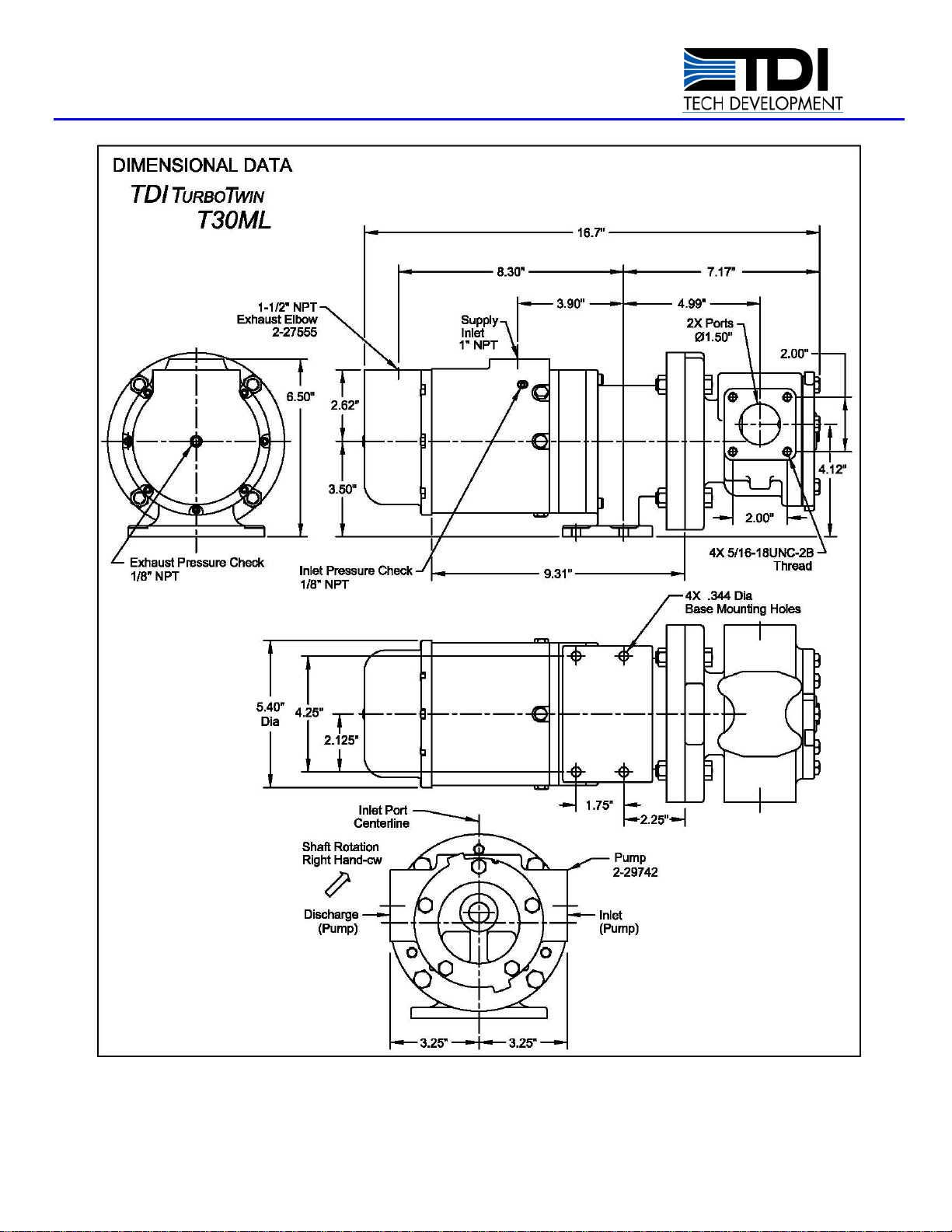
Figure 1. T30-M Lube Pump Motor
TDI TURBOTWIN™
FROM TECH DEVELOPMENT
Publication: T3-790, Rev. 2
Issued: January 9, 2013 Page 11
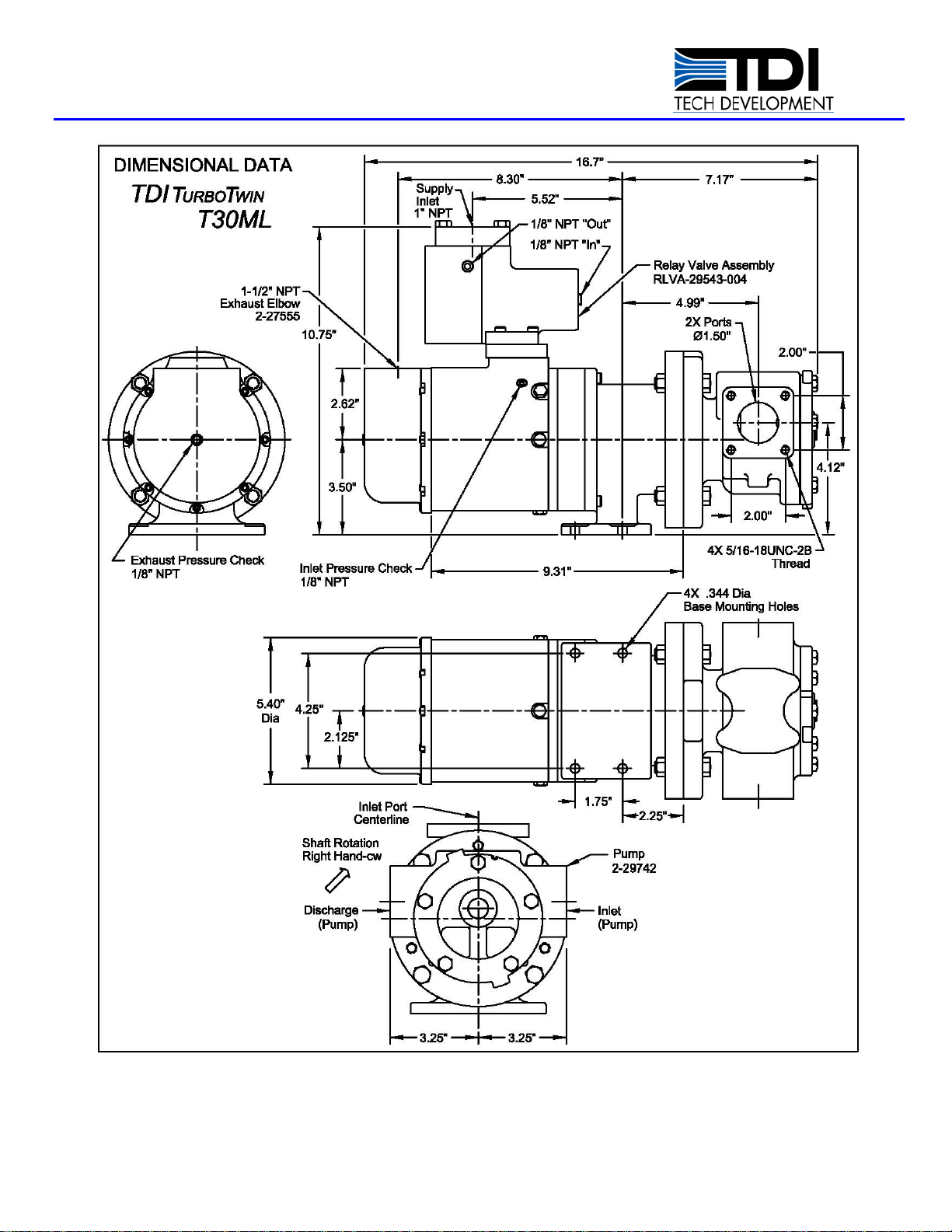
Figure 2. T30-M Lube Pump Motor w/Integral Relay Valve (Pneumatic)
TDI TURBOTWIN™
FROM TECH DEVELOPMENT
Page 12 Publication: T3-790, Rev. 2
Issued January 9, 2013
Figure 3. T30-M Lube Pump Motor w/Integral Relay Valve (Solenoid) for Air Only Operation

TDI TURBOTWIN™
FROM TECH DEVELOPMENT
Publication: T3-790, Rev. 2
Issued: January 9, 2013 Page 13
Figure 4. T30-M Lube Pump Motor w/Modified NEMA 56C Mounting Flange

TDI TURBOTWIN™
FROM TECH DEVELOPMENT
Page 14 Publication: T3-790, Rev. 2
Issued January 9, 2013
Figure 5. T30-M Lube Pump Motor w/NEMA 56C Mounting Flange
Table of contents
Other TDI Engine manuals


Popular Engine manuals by other brands

Sirius Satellite Radio
Sirius Satellite Radio SEM5 XS316 User & installation manual

Mercury
Mercury 4.3 TKS series Operation & maintenance manual

RCGF
RCGF 21CC-Twin Operator's manual

MTU
MTU 12V2000M93 operating instructions

Wacker Neuson
Wacker Neuson WM 80 Repair manual

Volvo Penta
Volvo Penta IPS 350 Installations


