manuals.online logo
Brands
  1. Home
  2. •
  3. Brands
  4. •
  5. TDK
  6. •
  7. Computer Hardware
  8. •
  9. TDK FReta iEB Series User manual

TDK FReta iEB Series User manual

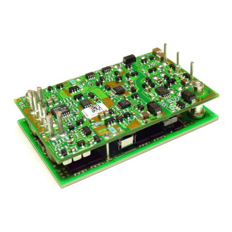
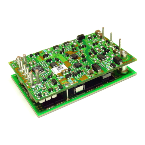
Advance Data Sheet: FReta iEB Series –Single Output Eighth Brick Bus Converter
©2004-2007 TDK Innoveta Inc.
10/29/2007
℡
(877) 498
-
0099
1/12
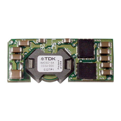
The FReta Serie offer an industry
standard 200W Eighth brick power module
featuring a high operating efficiency that
re ult in true u eable power. The FReta
module offer a fixed conver ion ratio of 4:1.
The unregulated power train topology
provide a low co t, high performance, high
reliability olution that i uitable for
di tributed power architecture that utilize an
intermediate voltage bu to power non-
i olated point of load converter .
Standard Features:
• Size – 58.4mm x 22.9 mm x 12.3
mm (2.30 in. x 0.90 in. x 0.485 in.)
• Long Thru-hole pin 4.57 mm
(0.180”)
• High efficiency – greater than 94%
• 2250Vdc i olation voltage
• Meet ba ic in ulation pacing
requirement
• Con tant witching frequency
• Indu try Standard Footprint
• Remote on/off (negative logic)
• Auto-recovering input over-voltage
protection
• Auto-recovering output over-
current protection
• Auto-recovering output hort circuit
protection
• Auto-recovering over-temperature
protection
• Applying for UL 60950 (U.S. and
Canada), VDE 0805, CB cheme
(IEC950), CE Mark (EN60950)
• ISO Certified manufacturing
facilitie
Optional Features:
• Remote on/off (po itive logic)
• Short Thru-hole pin 3.68 mm
(0.145”)
FReta iEB Series DC/DC Po er Modules
48V nput, 200W Output
Eighth Brick
Advance Data Sheet: FReta iEB Series –Single Output Eighth Brick Bus Converter
©2004-2007 TDK Innoveta Inc.
10/29/2007
℡
(877) 498
-
0099
2/12
Ordering information:
Product
dentifier
Package
Size
Platform nput
Voltage
Output
Current/
Power
Output
Units
Main
Output
Voltage
# of
Outputs
Safety
Class
Feature Set
i E B 48 017 A 120 V -
0 07
TDK Innoveta Eighth-
brick FReta 48V -
nominal
017 – 17A
Amp 120 – 12V
Single
07 – Standard
Option Table:
Feature
Set
Positive Logic
On/Off
Negative Logic
On/Off
0.180” Pin
Length
0.145” Pin
Length
00 X X
01 X X
06 X X
07 X X
Product Offering:
Code nput Voltage Output Voltage Output Current Maximum Output
Power Efficiency
iEB48017A120V 38-53V 12V 16.7A 200W 94.5%
3320 Matrix Drive Suite 100
Richard on, Texa 75082
Phone (877) 498-0099 Toll Free
(469) 916-4747
Fax (877) 498-0143 Toll Free
(214) 239-3101
upport@tdkinnoveta.com
http://www.tdkinnoveta.com/
Advance Data Sheet: FReta iEB Series –Single Output Eighth Brick Bus Converter
©2004-2007 TDK Innoveta Inc.
10/29/2007
℡
(877) 498
-
0099
3/12
Mechanical Specification:
Dimensions are in mm [in]. Unless otherwise specified tolerances are: x.x ± 0.5 [0.02], x.xx and x.xxx ± 0.25 [0.010].
Recommended Hole Pattern: (top view)
Pin Assignment:
PIN
FUNCTION PIN FUNCTION
1 Vin(+) 4 Vo(-)
2 On/Off 5 Vo(+)
3 Vin(-)
Pin ba e material i copper with plating; the maximum module weight i 30g (1.05 oz).
Advance Data Sheet: FReta iEB Series –Single Output Eighth Brick Bus Converter
©2004-2007 TDK Innoveta Inc.
10/29/2007
℡
(877) 498
-
0099
4/12
Absolute Maximum Ratings:
Stre in exce of Ab olute Maximum Rating may cau e permanent damage to the device
*Engineering e timation
nput Characteristics:
Unle otherwi e pecified, pecification apply over all Rated Input Voltage, Re i tive Load, and Temperature condition .
Characteristic Min Typ Max Unit Notes & Conditions
Operating Input Voltage 38 48 53 Vdc
Maximum Input Current --- --- 6.5* A Vin = 0 to Vin,max
Turn-on Voltage --- 36 --- Vdc
Turn-off Voltage 31* 34.5 --- Vdc
Hy tere i 0.5* 1.5 --- Vdc
Startup Delay Time from application of input
voltage
--- 3 --- mS Vo = 0 to 0.1*Vo,nom; on/off =on,
Io=Io,max, Tc=25˚C
Startup Delay Time from on/off --- 3 --- mS Vo = 0 to 0.1*Vo,nom; Vin = Vi,nom,
Io=Io,max,Tc=25˚C
Output Voltage Ri e Time --- 4 --- mS Io=Io,max,Tc=25˚C, Vo=0.1 to 0.9*Vo,nom
Input Over-voltage Turn-off --- 61 --- Vdc Input ri ing
Input Over-voltage Turn-on --- 59 --- Vdc Input falling
Input Over-voltage Hy tere i --- 2 --- Vdc
Inru h Tran ient --- --- 0.2 A
2
Input Reflected Ripple --- 50 --- mApp See input/output ripple and noi e
mea urement figure; BW = 20 MHz
*Engineering e timation
Caution: The power module are not internally fu ed. An external input line normal blow fu e with a maximum value of
10A i required; ee the Safety Con ideration ection of the data heet.
Characteristic Min Max Unit Notes & Conditions
Continuou Input Voltage -0.5 75 Vdc
Tran ient Input Voltage --- --- Vdc
I olation Voltage --- 2250 Vdc Ba ic in ulation
Storage Temperature -55 125 ˚C
Operating Temperature Range (Tc)
-40 123* ˚C
Mea ured at the location pecified in the thermal
mea urement figure. Maximum temperature varie
with model number, output current, and module
orientation – ee curve in thermal performance
ection of the data heet.
Advance Data Sheet: FReta iEB Series –Single Output Eighth Brick Bus Converter
©2004-2007 TDK Innoveta Inc.
10/29/2007
℡
(877) 498
-
0099
5/12
iEB48017A120V-000 through -007: 12V, 17A Output
Electrical Data:
Characteristic Min Typ Max Unit Notes & Conditions
Output Voltage Initial Setpoint --- 12 --- Vdc Vin=Vin,nom; Io=no load(0A); Tc = 25˚C
Output Voltage Tolerance 7.9* 12 13.7 Vdc Over all rated input voltage, load, and
temperature condition to end of life
Efficiency --- 94.5 --- % Vin=Vin,nom; Io=Io,max; Tc = 25˚C
Line Regulation --- 3.8 --- V Vin=Vin,min to Vin,max; Io=0A; Tc = 25˚C
Load Regulation --- 0.6 --- V Io=Io,min to Io,max; Vin=Vin,nom; Tc =
25˚C
Temperature Regulation --- 50 --- mV Tc=Tc,min to Tc,max; Io=Io,min
Vin=Vin,min 19.5
Vin=Vin,nom 17
Output Current
Vin=Vin,max
1* ---
16
A
At load le than Io,min the module will
operate correctly, but the output ripple may
increa e.
Output Current Limiting Thre hold --- 23 --- A Vo = 0.9*Vo,nom, Tc<Tc,max
Short Circuit Current --- 7 --- A Vo = 0.25V, Tc = 25˚C
--- 100 200* mVpp
Output Ripple and Noi e Voltage
--- 30 --- mVrm
Mea ured acro one 0.1uF, and 2x22uF
ceramic capacitor – ee input/output ripple
mea urement figure; BW = 20MHz
Dynamic Re pon e:
Recovery Time
Tran ient Voltage
---
---
25*
700*
---
---
uS
mV
di/dt = 1A/uS, Vin=Vin,nom; load tep from
0% to 100% of Io,max
Output Voltage Over hoot during tartup --- --- 5 % Vin=Vin,nom; Io=Io,max,Tc=25˚C
Ouput ripple Frequency --- 330 --- kHz Fixed
External Load Capacitance 0 --- 4000*& uF
I olation Re i tance 10 --- --- MΩ
& Contact TDK Innoveta for application that require additional capacitance or very low e r
*Engineering e timation
Advance Data Sheet: FReta iEB Series –Single Output Eighth Brick Bus Converter
©2004-2007 TDK Innoveta Inc.
10/29/2007
℡
(877) 498
-
0099
6/12
Electrical Characteristics:
iEB48017A120V-000 through -007: 12V, 17A Output
90
91
92
93
94
95
96
0 2 4 6 8 10 12 14 16 18 20
Output Current (A)
Efficiency, η
η
η
η(%)
Vin = 38V Vin = 48V Vin = 53V
0
2
4
6
8
10
12
14
0 2 4 6 8 10 12 14 16 18 20
Output Current (A)
Power Dissipation (W)
Vin = 38V Vin = 48V Vin = 53V
iEB48017A120V-000 Typical Efficiency v . Input
Voltage at Ta=25 degree .
iEB48017A120V-000 Typical Power Di ipation v .
Input Voltage at Ta=25 degree
8
9
10
11
12
13
14
0 2 4 6 8 10 12 14 16 18 20
Output Current (A)
Output Voltage (V)
Vin = 38V Vin = 48V
Vin = 53V Vin = 42V
iEB48017A120V-000 Typical Output Voltage v . Load
Current at Ta = 25 degree
iEB48017A120V-001 Typical tartup characteri tic from
on/off at full load, 1mS/div. Lower trace - on/off ignal
2V/div, upper trace – output voltage 5V/div.
iEB48017A120V-000 Typical tartup characteri tic
from input voltage application at full load, 1mS/div.
Lower trace - input voltage 20V/div, Upper trace –
output voltage 5V/div
iEB48017A120V-000 Typical tran ient re pon e
10uS/div. Output voltage re pon e to load tep from
0% to 100% of full load with output current lew rate of
1A/uS, Upper trace – output voltage 1V/div.
Advance Data Sheet: FReta iEB Series –Single Output Eighth Brick Bus Converter
©2004-2007 TDK Innoveta Inc.
10/29/2007
℡
(877) 498
-
0099
7/12
Electrical Characteristics (continued):
iEB48017A120V-000 through -007: 12V, 17A Output
8
9
10
11
12
13
14
0 2 4 6 8 10 12 14 16 18 20 22 24 26
Output Current (A)
Output Voltage (V)
Vin = 38V Vin = 48V Vin = 53V
iEB48017A120V-000 Typical Output Current Limit
Characteri tic v . Input Voltage at Ta=25 degree .
iEB48017A120V-000 Typical Output Ripple at nominal
Input voltage and full load at Ta=25 degree
0
1
2
3
4
5
6
31 33 35 37 39 41 43 45 47 49 51 53
nput Voltage (V)
nput Current (A)
Io_min = 0A Io_mid = 10.1A Io_max = 20.1A
0
2
4
6
8
10
12
14
31 33 35 37 39 41 43 45 47 49 51 53
nput Voltage (V)
Output Voltage (V)
Io_min = 0A Io_mid = 10.1A Io_max = 20.1A
iEB48017A120V-000 Typical Input Current v . Input
Voltage Characteri tic
iEB48017A120V-000 Typical Output Voltage v . Input
Voltage Characteri tic
Advance Data Sheet: FReta iEB Series –Single Output Eighth Brick Bus Converter
©2004-2007 TDK Innoveta Inc.
10/29/2007
℡
(877) 498
-
0099
8/12
Thermal Performance:
iEB48017A120V-000 through -007: 12V, 17A Output
0
2
4
6
8
10
12
14
16
18
25 35 45 55 65 75 85 95 105 115 125
Temperature (
o
C)
Output Current (A)
NC
0.5 m/ (100 LFM)
1.0 m/ (200 LFM)
2.0 m/ (400 LFM)
Tc MAX
0
2
4
6
8
10
12
14
16
18
25 35 45 55 65 75 85 95 105 115 125
Temperature (
o
C)
Output Current (A)
NC
0.5 m/ (100 LFM)
1.0 m/ (200 LFM)
2.0 m/ (400 LFM)
Tc MAX
iEB48017A120V-000 maximum output current v . ambient
temperature at nominal input voltage for airflow rate natural
convection (60lfm) to 400lfm with airflow from pin 3 to pin 1.
iEB48017A120V-000 maximum output current v . ambient
temperature at nominal input voltage for airflow rate natural
convection (60lfm) to 600lfm with airflow from output to input.
0.7
0.8
0.9
1.0
1.1
1.2
1.3
35 40 45 50 55 60
nput Voltage (V)
Derating Factor
iEB48017A120V-000 thermal mea urement location –
top view
iEB48017A120V-000 typical current derating ver u
line voltage with airflow = 1m/ (200lfm) and load
current greater than 4A.
Both the thermal curve provided and the example given above are ba ed upon mea urement made in TDK Innoveta’
experimental te t etup that i de cribed in the Thermal Management ection. Due to the large number of variable in
y tem de ign, TDK Innoveta recommend that the u er verify the module’ thermal performance in the end application.
The critical component hould be thermo coupled and monitored, and hould not exceed the temperature limit pecified in
the derating curve above. It i critical that the thermocouple be mounted in a manner that give direct thermal contact or
ignificant mea urement error may re ult. TDK Innoveta can provide module with a thermocouple pre-mounted to the
critical component for y tem verification te t .
Advance Data Sheet: FReta iEB Series –Single Output Eighth Brick Bus Converter
©2004-2007 TDK Innoveta Inc.
10/29/2007
℡
(877) 498
-
0099
9/12
Wind Tunnel Test Setup Figure
Dimen ion are
in millimeter and (inche ).
Thermal Management:
An important part of the overall y tem
de ign proce i thermal management;
thermal de ign mu t be con idered at all
level to en ure good reliability and lifetime
of the final y tem. Superior thermal de ign
and the ability to operate in evere
application environment are key element
of a robu t, reliable power module.
A finite amount of heat mu t be di ipated
from the power module to the urrounding
environment. Thi heat i tran ferred by the
three mode of heat tran fer: convection,
conduction and radiation. While all three
mode of heat tran fer are pre ent in every
application, convection i the dominant mode
of heat tran fer in mo t application .
However, to en ure adequate cooling and
proper operation, all three mode hould be
con idered in a final y tem configuration.
The open frame de ign of the power module
provide an air path to individual
component . Thi air path improve
convection cooling to the urrounding
environment, which reduce area of heat
concentration and re ulting hot pot .
Test Setup: The thermal performance data
of the power module i ba ed upon
mea urement obtained from a wind tunnel
te t with the etup hown in the wind tunnel
figure. Thi thermal te t etup replicate the
typical thermal environment encountered in
mo t modern electronic y tem with
di tributed power architecture . The
electronic equipment in networking, telecom,
wirele , and advanced computer y tem
operate in imilar environment and utilize
vertically mounted PCB or circuit card in
cabinet rack .
The power module, a hown in the figure, i
mounted on a printed circuit board (PCB)
and i vertically oriented within the wind
tunnel. The cro ection of the airflow
pa age i rectangular. The pacing
between the top of the module and a parallel
facing PCB i kept at a con tant (0.5 in).
The power module’ orientation with re pect
to the airflow direction can have a ignificant
impact on the module’ thermal
performance.
Thermal Derating: For proper application of
the power module in a given thermal
environment, output current derating curve
are provided a a de ign
guideline on the Thermal Performance
ection for the power module of intere t.
The module temperature hould be
mea ured in the final y tem configuration to
en ure proper thermal management of the
power module. For thermal performance
verification, the module temperature hould
be mea ured at the component indicated in
the thermal mea urement location figure on
the thermal performance page for the power
module of intere t. In all condition , the
power module hould be operated below the
maximum operating temperature hown on
the derating curve. For improved de ign
margin and enhanced y tem reliability, the
power module may be operated at
temperature below the maximum rated
operating temperature.
AIRFLOW
Air Velocity and Ambient
Temperature
Mea urement Location
A
I
F
L
O
W
12.7
(0.50)
Module
Centerline
Air Pa age
Centerline
Adjacent PCB
76 (3.0)
Advance Data Sheet: FReta iEB Series –Single Output Eighth Brick Bus Converter
©2004-2007 TDK Innoveta Inc.
10/29/2007
℡
(877) 498
-
0099
10/12
Heat tran fer by convection can be
enhanced by increa ing the airflow rate that
the power module experience . The
maximum output current of the power
module i a function of ambient temperature
(T
AMB
) and airflow rate a hown in the
thermal performance figure on the thermal
performance page for the power module of
intere t. The curve in the figure are hown
for natural convection through 2 m/ (400
ft/min). The data for the natural convection
condition ha been collected at 0.3 m/ (60
ft/min) of airflow, which i the typical airflow
generated by other heat di ipating
component in many of the y tem that
the e type of module are u ed in. In the
final y tem configuration , the airflow rate
for the natural convection condition can vary
due to temperature gradient from other heat
di ipating component .
Operating nformation:
Over-Current Protection: The power
module have current limit protection to
protect the module during output overload
and hort circuit condition . During overload
condition , the power module may protect
them elve by entering a hiccup current limit
mode. The module will operate normally
once the output current return to the
pecified operating range
Thermal Protection: When the power
module exceed the maximum operating
temperature, the module may turn off to
afeguard the power unit again t thermal
damage. The module will auto re tart a the
unit i cooled below the over temperature
thre hold.
Remote On/Off: - The power module have
an internal remote on/off circuit. The u er
mu t upply an open-collector or compatible
witch between the Vin(-) pin and the on/off
pin. The maximum voltage generated by
the power module at the on/off terminal i
15V. The maximum allowable leakage
current of the witch i 50uA. The witch
mu t be capable of maintaining a low ignal
Von/off < 1.2V while inking 1mA.
The tandard on/off logic i po itive logic.
The power module will turn on if terminal 2 i
left open and will be off if terminal 2 i
connected to terminal 3. If the po itive logic
circuit i not being u ed, terminal 2 hould
be left open.
An optional negative logic i available. The
power module will turn on if terminal 2 i
connected to terminal 3, and it will be off if
terminal 2 i left open. If the negative logic
feature i not being u ed, terminal 2 hould
be horted to terminal 3.
Vin(-)
On/ Off
Vin (+)
On/Off Circuit for positive or negative
logic
Advance Data Sheet: FReta iEB Series –Single Output Eighth Brick Bus Converter
©2004-2007 TDK Innoveta Inc.
10/29/2007
℡
(877) 498
-
0099
11/12
EMC Considerations: TDK Innoveta power
module are de igned for u e in a wide
variety of y tem and application . For
a i tance with de igning for EMC
compliance, plea e contact TDK Innoveta
technical upport.
nput mpedance:
The ource impedance of the power feeding
the DC/DC converter module will interact
with the DC/DC converter. To minimize the
interaction, a 33-100uF input electrolytic
capacitor hould be pre ent if the ource
inductance i greater than 2uH.
Reliability:
The power module are de igned u ing TDK
Innoveta’ tringent de ign guideline for
component derating, product qualification,
and de ign review . Early failure are
creened out by both burn-in and an
automated final te t. The MTBF i
calculated to be greater than 3.9M hour at
full output power and Ta = 40˚C u ing the
Telcordia SR-332 calculation method.
Improper handling or cleaning proce e can
adver ely affect the appearance, te tability,
and reliability of the power module . Contact
TDK Innoveta technical upport for guidance
regarding proper handling, cleaning, and
oldering of TDK Innoveta’ power module .
Quality:
TDK Innoveta’ product development
proce incorporate advanced quality
planning tool uch a FMEA and Cpk
analy i to en ure de ign are robu t and
reliable. All product are a embled at ISO
certified a embly plant .
nput/Output Ripple and Noise Measurements:
100KHz
Voutput
Cext
12
+
12uH
1 2
esr<0.7
Battery
100KHz
+
RLoad
12
esr<0.1
-
Vinput
220uF
12
Ground lane
33uF
12
-
The input reflected ripple i mea ured with a current probe and o cillo cope. The ripple
current i the current through the 12uH inductor.
The output ripple mea urement i made approximately 9 cm (3.5 in.) from the power module
u ing an o cillo cope and BNC ocket. The capacitor Cext i located about 5 cm (2 in.) from
the power module; it value varie from code to code and i found on the electrical data page
for the power module of intere t under the ripple & noi e voltage pecification in the Note &
Condition column.
Advance Data Sheet: FReta iEB Series –Single Output Eighth Brick Bus Converter
©2004-2007 TDK Innoveta Inc.
10/29/2007
℡
(877) 498
-
0099
12/12
Safety Considerations:
Check with TDK Innoveta for the current
tatu of afety approval on the iEB product
family.
For afety agency approval of the y tem in
which the DC-DC power module i in talled,
the power module mu t be in talled in
compliance with the creepage and clearance
requirement of the afety agency. The
i olation i ba ic in ulation. For
application requiring ba ic in ulation, care
mu t be taken to maintain minimum
creepage and clearance di tance when
routing trace near the power module.
A part of the production proce , the power
module are hi-pot te ted from primary and
econdary at a te t voltage of 1500Vdc.
To pre erve maximum flexibility, the power
module are not internally fu ed. An
external input line normal blow fu e with a
maximum value of 10A i required by afety
agencie . A lower value fu e can be
elected ba ed upon the maximum dc input
current and maximum inru h energy of the
power module.
When the upply to the DC-DC converter i
le than 60Vdc, the power module meet
all of the requirement for SELV. If the
input voltage i a hazardou voltage that
exceed 60Vdc, the output can be
con idered SELV only if the following
condition are met:
1) The input ource i i olated from the
ac main by reinforced in ulation.
2) The input terminal pin are not
acce ible.
3) One pole of the input and one pole
of the output are grounded or both
are kept floating.
4) Single fault te ting i performed on
the end y tem to en ure that under
a ingle fault, hazardou voltage
do not appear at the module output.
Warranty:
TDK Innoveta’ comprehen ive line of
power olution include efficient, high-
den ity DC-DC converter . TDK Innoveta
offer a three-year limited warranty.
Complete warranty information i li ted on
our web ite or i available upon reque t
from TDK Innoveta.
Information furnished by TDK Innoveta is believed to be accurate and reliable. However, TDK Innoveta assumes no
responsibility for its use, nor for any infringement of patents or other rights of third parties, which may result from its use. No
license is granted by implication or otherwise under any patent or patent rights of TDK Innoveta. TDK Innoveta components
are not designed to be used in applications, such as life support systems, wherein failure or malfunction could result in injury
or death. ll sales are subject to TDK Innoveta’s Terms and Conditions of Sale, which are available upon request.
Specifications are subject to change without notice.
i a trademark or regi tered trademark of TDK Corporation.
3320 Matrix Drive Suite 100
Richard on, Texa 75082
Phone (877) 498-0099 Toll Free
(469) 916-4747
Fax (877) 498-0143 Toll Free
(214) 239-3101
upport@tdkinnoveta.com
http://www.tdkinnoveta.com/

This manual suits for next models

1

Other TDK Computer Hardware manuals

TDK Metamere iAA Series Reference guide

TDK

TDK Metamere iAA Series Reference guide

TDK TFS Series TFSB10052450-1003A1 User manual

TDK

TDK TFS Series TFSB10052450-1003A1 User manual

TDK VLM Series VLM10555-2 User manual

TDK

TDK VLM Series VLM10555-2 User manual

TDK HHM Series HHM1713E2 User manual

TDK

TDK HHM Series HHM1713E2 User manual

TDK DEA Series DEA201990LT-9003D1 User manual

TDK

TDK DEA Series DEA201990LT-9003D1 User manual

TDK SLF Series SLF12565 User manual

TDK

TDK SLF Series SLF12565 User manual

TDK Supereta iQM Series User manual

TDK

TDK Supereta iQM Series User manual

TDK J Series JBW User manual

TDK

TDK J Series JBW User manual

TDK HHM Series HHM2202SA1 User manual

TDK

TDK HHM Series HHM2202SA1 User manual

TDK DEA Series DEA252450BT-7012D1 User manual

TDK

TDK DEA Series DEA252450BT-7012D1 User manual

TDK HHM Series HHM1589D1 User manual

TDK

TDK HHM Series HHM1589D1 User manual

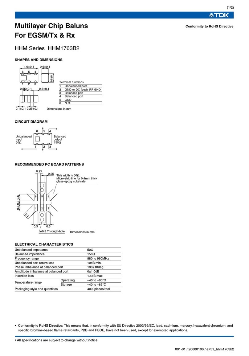
TDK HHM Series HHM1763B2 User manual

TDK

TDK HHM Series HHM1763B2 User manual

TDK Powereta iQP48070A033 User manual

TDK

TDK Powereta iQP48070A033 User manual

TDK HHM Series HHM1564A User manual

TDK

TDK HHM Series HHM1564A User manual

TDK DPX Series DPX161990DT-8003B1 User manual

TDK

TDK DPX Series DPX161990DT-8003B1 User manual

TDK EL Series EL0405 User manual

TDK

TDK EL Series EL0405 User manual

TDK HHM Series HHM2245SA1 User manual

TDK

TDK HHM Series HHM2245SA1 User manual

TDK DEA Series DEA162500LT-1217A1 User manual

TDK

TDK DEA Series DEA162500LT-1217A1 User manual

TDK DEA Series DEA200710LT-1238A1 User manual

TDK

TDK DEA Series DEA200710LT-1238A1 User manual

TDK HHM Series HHM1791A1 User manual

TDK

TDK HHM Series HHM1791A1 User manual

TDK HHM Series HHM2409 User manual

TDK

TDK HHM Series HHM2409 User manual

TDK HHM Series HHM1518A3 User manual

TDK

TDK HHM Series HHM1518A3 User manual

TDK Xeta Half Brick-iHG User manual

TDK

TDK Xeta Half Brick-iHG User manual

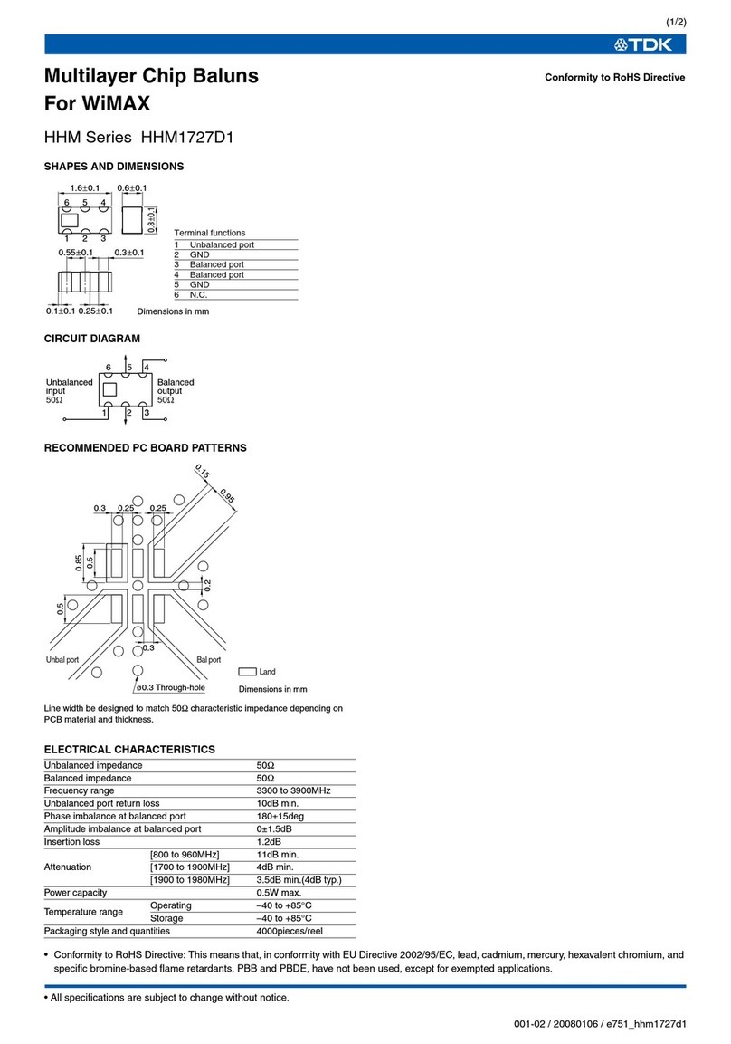
TDK HHM Series User manual

TDK

TDK HHM Series User manual

Popular Computer Hardware manuals by other brands

BBE ARS2 user manual

BBE

BBE ARS2 user manual

molex SST-DN4-PCU Hardware reference guide

molex

molex SST-DN4-PCU Hardware reference guide

Arcam FMJ AV8 Custom installation guide

Arcam

Arcam FMJ AV8 Custom installation guide

Joy-it EXPLORER 500 manual

Joy-it

Joy-it EXPLORER 500 manual

AMX EXB-COM2 quick start guide

AMX

AMX EXB-COM2 quick start guide

STEINWAY LYNGDORF Steinway & Sons P100 owner's manual

STEINWAY LYNGDORF

STEINWAY LYNGDORF Steinway & Sons P100 owner's manual

Intel NUC 13 Pro Desk Edition user guide

Intel

Intel NUC 13 Pro Desk Edition user guide

Sunix PC104 user manual

Sunix

Sunix PC104 user manual

Aaeon SBC-656 manual

Aaeon

Aaeon SBC-656 manual

Kodak MULTILOADER 700 Service manual

Kodak

Kodak MULTILOADER 700 Service manual

BCM Advanced Research BC45Q manual

BCM Advanced Research

BCM Advanced Research BC45Q manual

Motorola VME/10 installation guide

Motorola

Motorola VME/10 installation guide

Kontron CP6003-SA user guide

Kontron

Kontron CP6003-SA user guide

Xcellon DRD-501 user manual

Xcellon

Xcellon DRD-501 user manual

SyncMOS Technologies International MSM9066 user manual

SyncMOS Technologies International

SyncMOS Technologies International MSM9066 user manual

National Instruments NI sbRIO-960x user guide

National Instruments

National Instruments NI sbRIO-960x user guide

Security Labs SLX912 owner's manual

Security Labs

Security Labs SLX912 owner's manual

Linear Analog Devices LTM4673 user manual

Linear

Linear Analog Devices LTM4673 user manual

manuals.online logo
manuals.online logoBrands
  • About & Mission
  • Contact us
  • Privacy Policy
  • Terms and Conditions

Copyright 2025 Manuals.Online. All Rights Reserved.