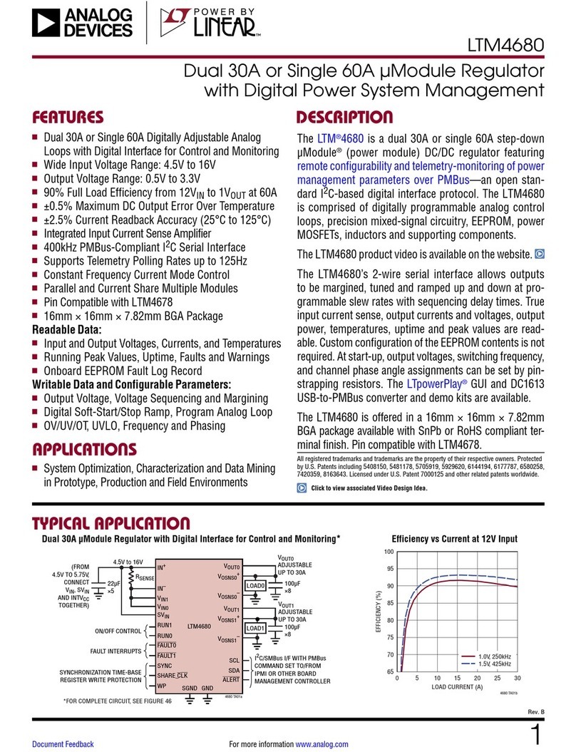
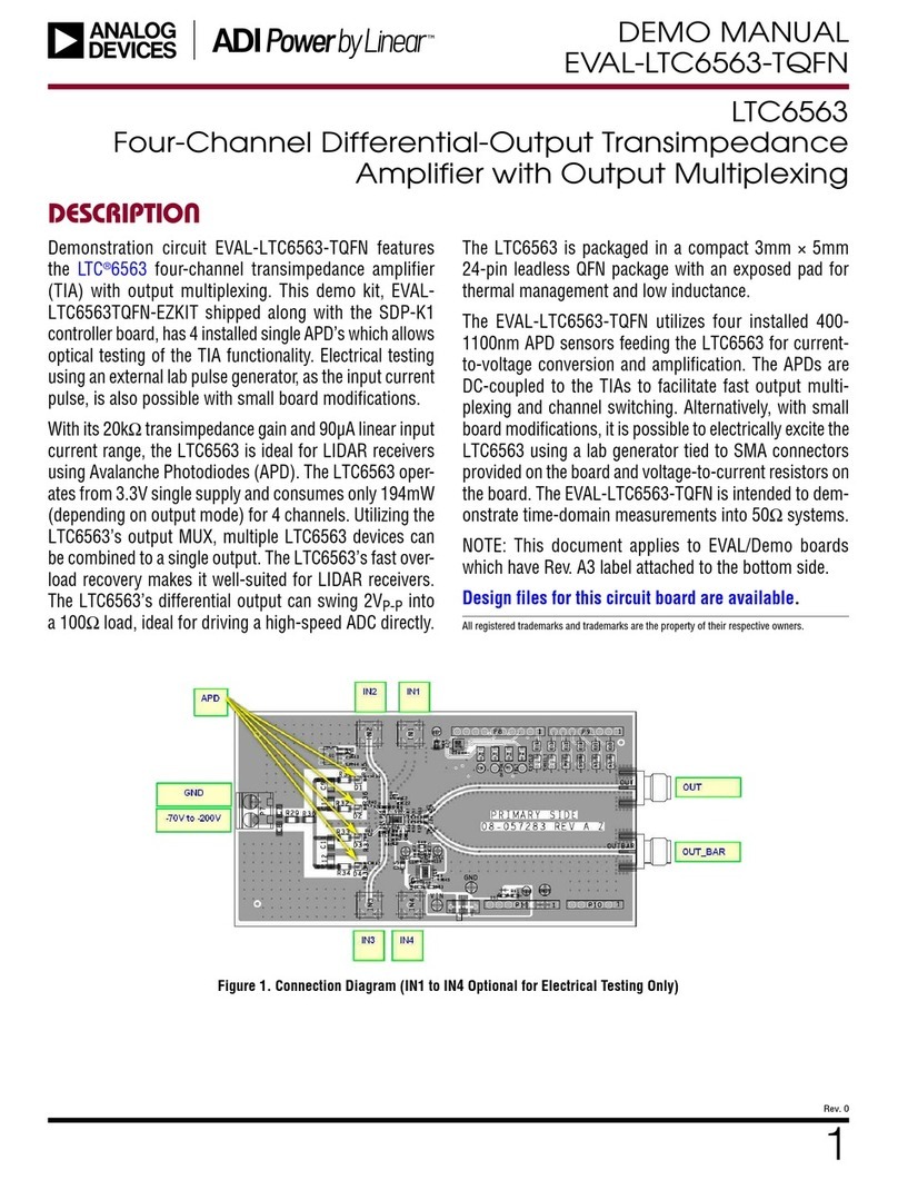
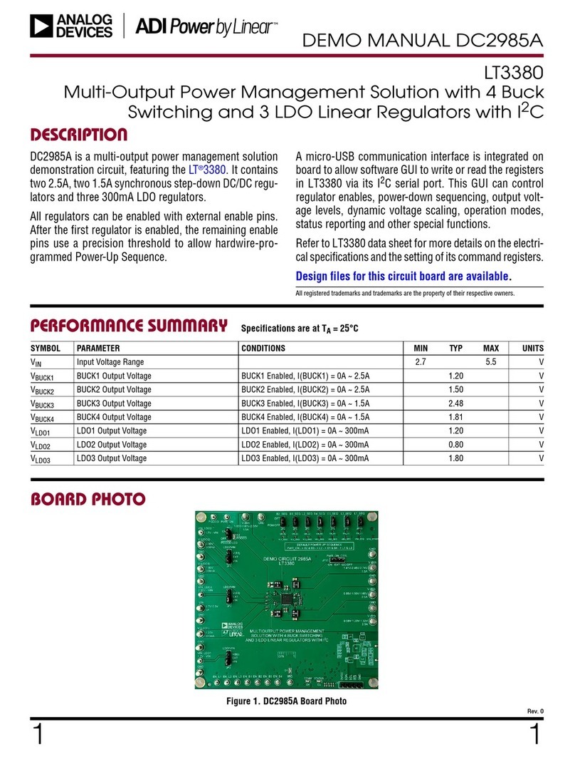
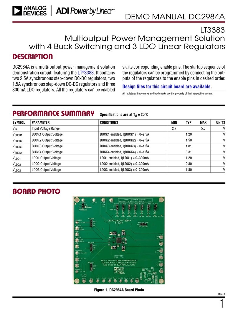
Linear Analog Devices LTM4673 User manual

LTM4673
1
Rev. 0
For more information www.analog.comDocument Feedback
TYPICAL APPLICATION
FEATURES DESCRIPTION
Quad Output μModule Regulator with
Digital Power System Management
The LTM
®
4673 is a quad output, dual 12A and dual 5A,
switching mode DC/DC step-down μModule (powermodule)
regulator integrated with 4-channel Power System Manager
used to sequence, trim (servo), margin, supervise, manage
faults, provide telemetry, and create fault logs. Operating
over an input voltage range of 4.5V to 15V, the LTM4673
supports an output voltage range of 0.6V to 3.3V for 12A
channels and 0.6V to 5.5V for 5A channels. Only bulk input
and output capacitors are needed.
The LTM4673’s 2-wire serial interface allows outputs
to be precisely margined, tuned and programmable
sequenced up and down. An internal 16-bit ADC monitors
and supervises input and all four output voltages, currents
and temperatures. Faults can be programmed for
overcurrent and undercurrent, voltage and temperature
threshold limits for four output channels as well as over
and undervoltage for the input.
The LTM4673 is offered in a 16mm × 16mm × 4.72mm
BGA package with RoHS compliant terminal finish.
Configurable Output Array
12A
12A
5A
5A 10A
24A 12A
12A
5A
5A 10A
24A
All registered trademarks and trademarks are the property of their respective owners. Protected
by U.S. patents, including 5481178, 5847554, 6580258, 6304066, 6476589, 6774611,
7382303, 7420359 and 8648623.
APPLICATIONS
n Quad Outputs, Dual 12A and Dual 5A, Step-Down
μModule
®
Regulator with Digital Interface
n Wide Input Voltage Range: 4.5V to 15V
n Dual 12A DC Output From 0.6V to 3.3V
n Dual 5A DC Output From 0.6V to 5.5V
n ±0.5% Total Output Voltage Regulation with Servo
n ±5% Current Readback Accuracy in 12A Channels
n 400kHz PMBus-Compliant I2C Serial Interface
n Integrated 16-Bit ΔΣADC
n Accurate Monitoring Input and Four Output Voltages,
Currents, and Temperatures
n Digital Programmable Output Voltage Trim,
Sequencing and Margining for Each Channel
n Manage Faults and Warnings
n Onboard EEPROM Fault Log Record
n Dual True Differential Sensing Amplifier
n Parallelable Output for Higher Output Current
n Drop-In Pin Compatible with Quad Output LTM4671
Non-PSM μModule Regulator
n 16mm × 16mm × 4.72mm BGA Package
n Telecom, Networking and Industrial Equipment
n Multi-Rail Point of Load Regulation
n FPGAs, DSPs and ASICs Application
Efficiency vs Load Current,
12V Input
Dual 12A, Dual 5A Output DC/DC µModule Regulator with Digital Power System Management
LOAD CURRENT (A)
0
2
4
6
8
10
12
70
72
74
76
78
80
82
84
86
88
90
EFFICIENCY (%)
4673 TA01b
VOUT2 = 1.8V
VOUT1 = 1.2V
VOUT0 = 1.0V
VOUT3 = 0.9V
RSENSE
100μF
90.9k
60.4k
47μF
30.1k
100μF
121k
715k
402k
787k
590k
47μF
100μF
×2
LTM4673
VDAC3
VIN
VIN_D
VINSNS
SDA
SCL
ALERT
FAULT0
FAULT1
SHARECLK
WP
SGND
VOUT0
VOSNS0+
VOSNS0–
ON/OFF
CONTROL
SVIN0
SVIN3
IINSNSM
IINSNSP
4.5V TO 15V
CONTROL1
I2C/SMBus I/F WITH PMBus
COMMAND SET TO/FROM
IPMI OR OTHER BOARD
MANAGEMENT CONTROLLER
SYNCHRONIZATION
TIME-BASE
REGISTER WRITE
PROTECTION
FB0
VOUT1
VOSNS1+
VOSNS1–
FB1
VOUT2
VOSNS2+
VOSNS2–
FB2
VOUT3
VOSNS3+
VOSNS3–
FB3
VDAC2
VDAC1
VDAC0
GND
CONTROL2
CONTROL3
CONTROL0
VOUT0
1.0V/12A
VOUT1
1.2V/5A
VOUT3
0.9V/12A
VOUT2
1.8V/5A
22μF
×4
4673 TA01a

LTM4673
2
Rev. 0
For more information www.analog.com
TABLE OF CONTENTS
Features...................................................................1
Applications ..............................................................1
Typical Application ......................................................1
Description................................................................1
Absolute Maximum Ratings............................................4
Pin Configuration ........................................................5
Order Information........................................................5
Electrical Characteristics ...............................................6
PMBus Timing Diagram............................................... 12
Typical Performance Characteristics ............................... 13
Pin Functions ........................................................... 17
Pins for Dual 12A Channels:....................................................17
Pins for Dual 5A Channels:......................................................19
Pins for Digital Power System Management...........................20
Block Diagram.......................................................... 21
Decoupling Requirements............................................ 22
Operation................................................................ 22
EEPROM .............................................................................24
AUXFA U LT ................................................................................24
RESET ......................................................................................25
PMBus Serial Digital Interface ................................................25
PMBus................................................................................25
Device Address...................................................................25
Processing Commands ......................................................26
PMBus Command Summary ......................................... 29
Applications Information ............................................. 36
Overview..................................................................................36
Powering LTM4673 .................................................................36
VIN to VOUT Step-Down Ratios ................................................36
Input Decoupling Capacitors ...................................................36
Output Voltage Programming and Trimming ..........................37
Output Decoupling Capacitors ................................................37
Forced Continuous Current Mode (CCM) ................................37
Discontinuous Mode/Burst Mode Operation...........................37
Operating Frequency ...............................................................38
Frequency Synchronization and Clock In ................................38
Soft-Start.................................................................................39
Power Good.............................................................................39
Stability Compensation ...........................................................39
Setting Command Register Values..........................................39
MEASURING INPUT CURRENT ...............................................39
MEASURING INPUT VOLTAGE ................................................40
MEASURING INPUT POWER...................................................40
Measuring INPUT ENERGY......................................................41
Sequence, Servo, Margin and Restart Operations ..................41
Command Units On or Off..................................................41
On Sequencing ...................................................................41
On State Operation.............................................................42
Servo Modes ......................................................................42
DAC Modes.........................................................................42
Margining ...........................................................................42
Off Sequencing...................................................................43
VOUT Off Threshold Voltage................................................43
Automatic Restart via MFR_RESTART_DELAY and
CONTROL Pin.....................................................................43
Fault Management...................................................................43
Output Overvoltage, Undervoltage, Overcurrent and
Undercurrent Faults............................................................43
Output Overvoltage, Undervoltage, and Overcurrent
Warnings ............................................................................43
Configuring the AUXFA U LT Output.....................................44
Multichannel Parallel Operation ..............................................44
Input RMS Ripple Current Cancellation...................................44
Cascade Sequence ON with Time-Based Sequence OFF....44
Output Voltage Tracking.....................................................45
Multi-Channel Fault Management ......................................49
Interconnect Between Multiple Analog Devices POWER
MANAGERS.............................................................................50
Connecting the DC1613 USB to I2C/SMBus/PMBus
Controller to the LTM4673 in System ................................50
LTpowerPlay:An Interactive GUI for Power Managers..................... 53
Four-Step Resistor Selection Procedure for Resistors
between VDAC and VFB Pins................................................53
Thermal Considerations and Output Current Derating.......55
Safety Considerations .............................................................61
Layout Checklist/Example.......................................................61
Typical Applications ................................................... 63
PMBus Command Description ....................................... 67
Addressing and Write Protect .................................................67
PAGE...................................................................................67
WRITE_PROTECT...............................................................68
WRITE-PROTECT Pin .........................................................68
MFR_PAGE_FF_MASK .......................................................68
MFR_I2C_BASE_ADDRESS...............................................69
MFR_COMMAND_PLUS ....................................................69
MFR_DATA_PLUS0 and MFR_DATA_PLUS1 ....................69
MFR_STATUS_PLUS0, and MFR_STATUS_PLUS1...........69
Reading Fault Log Using Command Plus and Mfr_data_
plus0...................................................................................70
Reading Energy Using MFR_COMMAND_PLUS and MFR_
DATA_PLUS0......................................................................71
Peek Operation Using Mfr_data_plus0..............................71
Enabling and Disabling Poke Operations............................71
Poke Operation Using Mfr_data_plus0..............................71
Command Plus Operations Using Mfr_data_plus1.................... 72
On/Off Control, Margining and Configuration .........................72
OPERATION ........................................................................72
ON_OFF_CONFIG................................................................73
MFR_CONFIG_LTM4673....................................................74
MFR_CONFIG2_LTM4673..................................................75
MFR_CONFIG3_LTM4673..................................................76
MFR_CONFIG_ALL_LTM4673...........................................77
Programming User EEPROM Space........................................78
STORE_USER_ALL and RESTORE_USER_ALL ................79
Bulk Programming the User EEPROM Space.....................79
MFR_EE_UNLOCK..............................................................79
MFR_EE_ERASE ................................................................80
MFR_EE_DATA...................................................................80
Response When Part Is Busy.............................................81
MFR_EE Erase and Write Programming Time ...................81

LTM4673
3
Rev. 0
For more information www.analog.com
Input Voltage Commands and Limits ......................................81
VIN_ON, VIN_OFF, VIN_OV_FAULT_LIMIT, VIN_OV_WARN_
LIMIT, VIN_UV_WARN_LIMIT and
VIN_UV_FAULT_LIMIT .......................................................81
INPUT Current and ENERGY....................................................82
Energy Measurement and Reporting..................................82
MFR_EIN ...........................................................................83
MFR_EIN_CONFIG .............................................................83
MFR_IIN_CAL_GAIN..........................................................84
MFR_IIN_CAL_GAIN_TC....................................................84
Output Voltage Commands and Limits....................................85
VOUT_MODE ......................................................................86
VOUT_COMMAND, VOUT_MAX, VOUT_MARGIN_HIGH,
VOUT_MARGIN_LOW, VOUT_OV_FAULT_LIMIT, VOUT_OV_
WARN_LIMIT, VOUT_UV_WARN_LIMIT, VOUT_UV_FAULT_
LIMIT, POWER_GOOD_ON and POWER_GOOD_OFF........86
MFR_VOUT_DISCHARGE_THRESHOLD ............................86
MFR_DAC...........................................................................86
Output Current Commands and Limits....................................87
IOUT_CAL_GAIN ................................................................87
IOUT_OC_FAULT_LIMIT, IOUT_OC_WARN_LIMIT and
IOUT_UC_FAULT_LIMIT.....................................................88
MFR_IOUT_CAL_GAIN_TC ................................................88
External Temperature Commands and Limits .........................88
OT_FAULT_LIMIT, OT_WARN_LIMIT, UT_WARN_LIMIT and
UT_FAULT_LIMIT ...............................................................89
MFR_TEMP_1_GAIN and MFR_TEMP_1_OFFSET ...................89
MFR_T_SELF_HEAT, MFR_IOUT_CAL_GAIN_TAU_INV and
MFR_IOUT_CAL_GAIN_THETA ..........................................89
Sequencing Timing Limits and Clock Sharing.........................91
TON_DELAY, TON_RISE, TON_MAX_FAULT_LIMIT and
TOFF_DELAY ......................................................................91
MFR_RESTART_DELAY .....................................................92
Clock Sharing .....................................................................92
Watchdog Timer and Power Good...........................................92
MFR_PWRGD_EN ..............................................................92
MFR_POWERGOOD_ASSERTION_DELAY.........................93
Watchdog Operation...........................................................93
MFR_WATCHDOG_T_FIRST and MFR_WATCHDOG_T ......93
Fault Responses ......................................................................94
Clearing Latched Faults......................................................94
VOUT_OV_FAULT_RESPONSE and VOUT_UV_FAULT_
RESPONSE .........................................................................94
IOUT_OC_FAULT_RESPONSE and IOUT_UC_FAULT_
RESPONSE .........................................................................95
OT_FAULT_RESPONSE, UT_FAULT_RESPONSE, VIN_OV_
FAULT_RESPONSE and VIN_UV_FAULT_RESPONSE........96
TON_MAX_FAULT_RESPONSE..........................................97
MFR_RETRY_DELAY..........................................................97
MFR_RETRY_COUNT.........................................................97
Shared External Faults ............................................................98
MFR_FAULTB0_PROPAGATE and MFR_FAULTB1_
PROPAGATE .......................................................................98
MFR_FAULTB0_RESPONSE and MFR_FAULTB1_
RESPONSE .........................................................................98
Fault Warning and Status ........................................................99
CLEAR_FAULTS .................................................................99
STATUS_BYTE..................................................................100
STATUS_WORD................................................................100
STATUS_VOUT .................................................................101
STATUS_IOUT ..................................................................101
STATUS_INPUT................................................................101
STATUS_TEMPERATURE .................................................102
STATUS_CML ...................................................................102
STATUS_MFR_SPECIFIC..................................................103
MFR_PADS.......................................................................103
MFR_COMMON................................................................104
Telemetry...............................................................................105
READ_VIN ........................................................................105
READ_IIN .........................................................................105
READ_PIN ........................................................................105
READ_VOUT .....................................................................105
READ_IOUT......................................................................106
MFR_IIN_PEAK ................................................................106
MFR_IIN_MIN ..................................................................106
MFR_PIN_PEAK...............................................................106
MFR_PIN_MIN .................................................................106
READ_TEMPERATURE_1 .................................................106
READ_TEMPERATURE_2.................................................106
READ_POUT.....................................................................106
MFR_READ_IOUT ............................................................107
MFR_IOUT_SENSE_VOLTAGE..........................................108
MFR_VIN_PEAK ...............................................................108
MFR_VOUT_PEAK............................................................108
MFR_IOUT_PEAK.............................................................108
MFR_TEMPERATURE_1_PEAK ........................................108
MFR_VIN_MIN .................................................................108
MFR_VOUT_MIN ..............................................................108
MFR_IOUT_MIN ...............................................................108
MFR_TEMPERATURE_1_MIN ..........................................109
Fault Logging.........................................................................109
Fault Log Operation..........................................................109
MFR_FAULT_LOG_STORE ...............................................109
MFR_FAULT_LOG_RESTORE...........................................109
MFR_FAULT_LOG_CLEAR ...............................................110
MFR_FAULT_LOG_STATUS .............................................110
MFR_FAULT_LOG.............................................................110
MFR_FAULT_LOG Read Example.....................................113
Identification/Information ..................................................... 117
CAPABILITY......................................................................118
PMBus_REVISION............................................................ 118
MFR_SPECIAL_ID............................................................ 118
MFR_SPECIAL_LOT.........................................................118
User Scratchpad....................................................................118
USER_DATA_00, USER_DATA_01, USER_DATA_02,
USER_DATA_03, USER_DATA_04, MFR_LTC_
RESERVED_1 and MFR_LTC_RESERVED_2....................118
Package Description .................................................119
Package Photos .......................................................122
Design Resources ....................................................122
Related Parts ..........................................................122
TABLE OF CONTENTS

LTM4673
4
Rev. 0
For more information www.analog.com
ABSOLUTE MAXIMUM RATINGS
Digital Supply Voltages:
VIN_D...................................................... –0.3V to 15V
VDD33.................................................... –0.3V to 3.6V
VDD25.................................................. –0.3V to 2.75V
Digital Input/Output Voltages:
ALERT, SDA, SCL, CONTROL0, CONTROL1,
CONTROL2, CONTROL3 ....................... –0.3V to 3.6V
PWRGD, SHARECLK, WDI/RESET,
WP, FA U LT 0, FA U LT 1............................. –0.3V to 3.6V
ASEL0, ASEL1 ....................................... –0.3V to 3.6V
VINSNS........................................................ –0.3V to 15V
IINSNSP, IINSNSM to VINSNS .................... –0.3V to 0.3V
IINSNSP, IINSNSM ..................................... –0.3V to 15V
AUXFA U LT .............................................. –0.3V to 15V
VDAC[3:0] .................................................. –0.3V to 6V
TSENSE[3:0] ............................................ –0.3V to 3.6V
VIN, SVIN0, SVIN3........................................ –0.3V to 15V
VOUT0, VOUT3............................................. –0.3V to 3.6V
VOUT1, VOUT2................................................ –0.3V to 6V
INTVCC0, INTVCC12, INTVCC3 .................... –0.3V to 3.6V
FREQ0, FREQ12, FREQ3............................ –0.3V to 3.6V
FB0, FB1, FB2, FB3.................................... –0.3V to 3.6V
COMP0a, COMP0b, COMP3a, COMP3b,
COMP1, COMP2,................................... –0.3V to 3.6V
RUN0, RUN1, RUN2, RUN3........................ –0.3V to 15V
TRACK/SS0, TRACK/SS1, TRACK/SS2,
TRACK/SS3 .......................................... –0.3V to 3.6V
PWRGD0, PWRGD1, PWRGD2, PWRGD3...–0.3V to 3.6V
VOSNS0+, VOSNS0–, VOSNS3+, VOSNS3–....... –0.3V to 3.6V
VOSNS1+, VOSNS1–, VOSNS2+, VOSNS2–........... –0.3V to 6V
TSENSE0+, TSENSE0–, TSENSE3+,
TSENSE3–............................................. –0.3V to 0.8V
TMON ....................................................... –0.3V to 3.6V
MODE/CLKIN0, MODE/CLKIN12, MODE/CLKIN3,
CLKOUT0, CLKOUT3............................. –0.3V to 3.6V
Operating Junction Temperature
(Notes 2, 9)........................................ –40°C to 125°C
Storage Temperature Range .................. –55°C to 125°C
Peak Solder Reflow Body Temperature................. 245°C
(Note 1)

LTM4673
5
Rev. 0
For more information www.analog.com
PIN CONFIGURATION
ORDER INFORMATION
PART NUMBER PAD OR BALL FINISH
PART MARKING PACKAGE
TYPE
MSL
RATING
TEMPERATURE RANGE
(SEE NOTE 2)DEVICE FINISH CODE
LTM4673EY#PBF SAC305 (RoHS) LTM4673Y e1 BGA 4 –40°C to 125°C
LTM4673IY#PBF
• Contact the factory for parts specified with wider operating temperature
ranges. *Pad or ball finish code is per IPC/JEDEC J-STD-609.
• This product is not recommended for second side reflow.
• Recommended LGA and BGA PCB Assembly and Manufacturing
Procedures
• LGA and BGA Package and Tray Drawings
W
V
U
T
R
P
N
M
L
K
J
H
G
F
E
D
C
B
A
1918171615149 10 11 12 138761 2 3 4 5
GND
VDAC3
SGND
SGND
SGND
GND
GND
GND GND
GND GND
INTVCC0
VOSNS0+
VOSNS1–
MODE/
CLKIN12
MODE/
CLKIN3PHMODE3
PMODE0
VIN
VIN
TRACK/
SS1
PWRGD1
VOSNS0–
VOSNS2+
COMP3a
TRACK/
SS3CLKOUT3
GNDFB2
FB3
PWRGD2COMP2
COMP3b
TSENSE3+TSENSE3–
SVIN3
VIN
INTVCC3
VOUT3
TMON FREQ12
VOSNS3–
RUN2
FREQ3RUN3
PWRGD3
GNDFB0
COMP0aFB1
VOSNS1+
GND COMP1
VOUT1
VOUT2
RUN1
VDAC2
VDAC1
FREQ0
SVIN0
RUN0 ALERTB SCL SDA FAULT1PWRGD
CTRL1 WP
TSENSE2
ASEL0
ASEL1
FAULT0
VINSNS
VIN_D
VDAC0
SGND
VOUT0
GND
BGA PACKAGE
361-LEAD (16mm × 16mm × 4.72mm)
θJCTOP = 12.3 °C/W, θJCBOTTOM =2.2 °C/W, θJA = 8.2 °C/W (NOTE 18)
WEIGHT = 3.0g
TOP VIEW
TSENSE0–TSENSE0+
TRACK/
SS0
CLKOUT0 PWRGD0
CTRL3SHARECLKGND
VIN
MODE/
CLKIN0
AUXFAULT
CTRL2CTRL0
VDD25
VDD33
WDI/
RESET
COMP0b
TSENSE1
INTVCC12 DNC
VOSNS2–
IINSNSP
IINSNSM
VOSNS3+
GND
TRACK/
SS2
SGND
VIN
GND

LTM4673
6
Rev. 0
For more information www.analog.com
ELECTRICAL CHARACTERISTICS
The ldenotes the specifications which apply over the specified internal
operating temperature range. Specified as each individual output channel. TA= 25°C (Note 2), SVIN = VIN = 12V, unless otherwise
noted. Per the typical application in Figure53.
SYMBOL PARAMETER CONDITIONS MIN TYP MAX UNITS
Switching Regulator Section: (12A Channels)
VIN Input DC Voltage l4.5 15 V
VOUT(RANGE) Output Voltage Range l0.6 3.3 V
VOUT(DC) Output Voltage, Total Variation with
Line and Load
CIN = 22μF, COUT = 100μF, CCM
SVIN = VIN = 4.5V to 15V, IOUT = 0A to 12A
VOUT = 1.5V (DAC Disconnect)
VOUT = 0.6V to 3.3V, (DAC Soft Connect), (Note 12)
l
1.5
0.5
%
%
IQ(VIN) Input Supply Bias Current MODE/CLKIN = 3.3V, FCM, VOUT = 1.5V, IOUT = 0A
MODE/CLKIN = 0V, DCM, VOUT = 1.5V, IOUT = 0A
RUN0–3 = 0V, Shutdown
75
3
250
mA
mA
µA
IS(VIN) Input Supply Current VOUT = 1.5V, IOUT = 12A 1.7 A
IOUT(DC) Output Continuous Current Range VOUT = 1.5V (Note 14) 12 A
ΔVOUT(LINE)/VOUT Line Regulation Accuracy VOUT = 1.5V, VIN = 4.5V to 15V, IOUT = 0A l0.01 0.05 %/V
ΔVOUT(LOAD)/VOUT Load Regulation Accuracy VOUT = 1.5V, IOUT = 0A to 12A (DAC Disconnect) l0.2 0.5 %
VOUT(AC) Output Ripple Voltage IOUT = 0A, COUT = 3× 100µF Ceramic
VOUT = 1.5V
18 mV
ΔVOUT(START) Turn-On Overshoot IOUT = 0A, COUT = 3×100µF Ceramic,
VOUT = 1.5V (Note 12)
5 mV
tSTART Turn-On Time TRACK/SS = 0.1µF,
SVIN = VIN = 12V, VOUT = 1.5V, COUT = 3×100µF Ceramic
1 ms
ΔVOUTLS Peak Deviation for Dynamic Load Load: 0% to 25% to 0% of Full Load
VOUT = 1.5V, COUT = 3×100µF Ceramic (Note 12)
±50 mV
tSETTLE Settling Time for Dynamic Load Step Load: 0% to 25% to 0% of Full Load
VOUT = 1.5V, COUT = 3×100µF Ceramic (Note 12)
30 µs
IOUTPK Output Current Limit VOUT = 1.5V 12.5 A
VFB Voltage at VFB Pin IOUT = 0A, VOUT = 1.5V l0.594 0.6 0.606 V
IFB Current at VFB Pin (Note 16) ±50 nA
RFB(TOP) Resistor Between VOUT and VFB Pins 60.05 60.40 60.75 kΩ
VRUN RUN Pin ON Threshold VRUN Rising
Hysteresis
1.10 1.20
150
1.35 V
mV
UVLO Undervoltage Lockout PWRGD Falling
Hysteresis
2.45 2.6
0.4
2.75 V
V
ITRACK/SS Track Pin Soft-Start Pull-Up Current TRACK/SS = 0V 6 µA
tON(MIN) Minimum On-Time (Note 13) 25 ns
tOFF(MIN) Minimum Off-Time (Note 16) 80 ns
VPWRGD PWRGD Trip Level VFB With Respect to Set Output
VFB Ramping Negative
VFB Ramping Positive
–10.5
5
–8
8
–5
10.5
%
%
RPWRGD PWRGD Pull-Down Resistance 1mA Load 8 15 Ω
INTVCC Internal VCC Voltage 3.0 3.3 3.6 V
FREQ Default Switching Frequency 600 kHz
CLKIN0, CLKIN3 CLKIN Input High Threshold
CLKIN Input Low Threshold
1
0.3
V
V

LTM4673
7
Rev. 0
For more information www.analog.com
ELECTRICAL CHARACTERISTICS
The ldenotes the specifications which apply over the specified internal
operating temperature range. Specified as each individual output channel. TA= 25°C (Note 2), SVIN = VIN = 12V, unless otherwise
noted. Per the typical application in Figure53.
SYMBOL PARAMETER CONDITIONS MIN TYP MAX UNITS
Switching Regulator Section: (5A Channels)
VIN Input DC Voltage l4.5 15 V
VOUT(RANGE) Output Voltage Range l0.6 5.5 V
VOUT(DC) Output Voltage, Total Variation with
Line and Load
CIN = 22μF, COUT = 100μF, CCM
SVIN = VIN = 4.5V to 15V, IOUT = 0A to 5A
VOUT = 1.5V (DAC Disconnect)
VOUT = 0.6V to 5.5V, (DAC Soft Connect), (Note 12)
l
1.5
0.5
%
%
IQ(VIN) Input Supply Bias Current MODE/CLKIN = GND, FCM, VOUT=1.5V, IOUT=0A
MODE/CLKIN = 3.3V, Burst Mode, VOUT = 1.5V, IOUT = 0A
20
4
mA
mA
IS(VIN) Input Supply Current VOUT = 1.5V, IOUT = 5A 0.75 A
IOUT(DC) Output Continuous Current Range VOUT = 1.5V (Note 14) 5 A
ΔVOUT(LINE)/VOUT Line Regulation Accuracy VOUT = 1.5V, VIN = 4.5V to 15V, IOUT = 0A l0.01 0.1 %/V
ΔVOUT(LOAD)/VOUT Load Regulation Accuracy VOUT = 1.5V, IOUT = 0A to 5A (DAC Disconnect) l0.2 0.5 %
VOUT(AC) Output Ripple Voltage IOUT = 0A, COUT = 100µF Ceramic
VOUT = 1.5V
4 mV
ΔVOUT(START) Turn-On Overshoot IOUT = 0A, COUT = 100µF Ceramic,
VOUT = 1.5V (Note 12)
22 mV
tSTART Turn-On Time TRACK/SS = 0.01µF,
VOUT = 1.5V, COUT = 100µF Ceramic
6 ms
ΔVOUTLS Peak Deviation for Dynamic Load Load: 0% to 25% to 0% of Full Load
VOUT = 1.5V, COUT = 100µF Ceramic (Note 12)
35 mV
tSETTLE Settling Time for Dynamic Load Step Load: 0% to 25% to 0% of Full Load
VOUT = 1.5V, COUT = 100µF Ceramic (Note 12)
60 µs
IOUTPK Output Current Limit VOUT = 1.5V 6 A
VFB Voltage at VFB Pin IOUT = 0A, VOUT = 1.5V l0.592 0.6 0.608 V
IFB Current at VFB Pin (Note 16) ±30 nA
RFB(TOP) Resistor Between VOUT and VFB Pins 60.05 60.40 60.75 kΩ
VRUN RUN Pin ON Threshold VRUN Rising
Hysteresis
1.15 1.25
250
1.35 V
mV
UVLO Undervoltage Lockout PWRGD Falling
Hysteresis
2.25 2.5
0.5
2.7 V
V
ITRACK/SS Track Pin Soft-Start Pull-Up Current TRACK/SS = 0V 1.5 µA
tON(MIN) Minimum On-Time (Note 13) 20 ns
tOFF(MIN) Minimum Off-Time (Note 16) 45 ns
VPWRGD PWRGD Trip Level VFB with Respect to Set Output
VFB Ramping Negative
VFB Ramping Positive
–10.5
5
–8
8
–5
10.5
%
%
RPWRGD PWRGD Pull-Down Resistance 10mA Load 25 Ω
INTVCC Internal VCC Voltage 3.0 3.3 3.6 V
FREQ Default Switching Frequency 1 MHz
MODE/CLKIN12 MODE/CLKIN12 High Threshold
MODE/CLKIN12 Low Threshold
1
0.3
V
V

LTM4673
8
Rev. 0
For more information www.analog.com
ELECTRICAL CHARACTERISTICS
The ldenotes the specifications which apply over the full operating
temperature range, otherwise specifications are at TJ= 25°C (Note 2). VIN_D = VINSNS = 12V, VDD33, VDD25 pins floating, unless
otherwise indicated.
SYMBOL PARAMETER CONDITIONS MIN TYP MAX UNITS
Digital Power Supply Characteristics
VIN_D VIN_D Supply Input Operating Range VDD33 Floating (Note 17) l4.5 15 V
IIN_D VIN_D Supply Current VDD33 Floating (Note 17) l10 13 mA
IVDD33 VDD33 Supply Current 3.13V ≤ VDD33 ≤ 3.47V, VIN_D = VDD33 (Note 17) l10 13 mA
VUVLO_VDD33 VDD33 Undervoltage Lockout VDD33 Ramping Up, VIN_D = VDD33 (Note 17) l2.25 2.55 2.8 V
VDD33 Undervoltage Lockout
Hysteresis
120 mV
VDD33 Supply Input Operating Range VIN_D = VDD33 l3.13 3.47 V
Regulator Output Voltage VIN_D= 4.5V l3.13 3.26 3.47 V
Regulator Output Short-Circuit
Current
VIN_D = 4.5V, VDD33 = 0V l50 90 140 mA
VDD25 Regulator Output Voltage VIN_D = 3.47V l2.35 2.5 2.65 V
Regulator Output Short-Circuit Current VIN_D = 3.47V, VDD25 = 0V l30 55 80 mA
tINIT Initialization Time Time from VIN Applied Until the TON_DELAY
Timer Starts (Note 17)
30 ms
DAC Output Characteristics (Note 17)
N_VDAC Resolution 10 Bits
VFS_VDAC Full-Scale Output Voltage
(Programmable)
DAC Code = 0x3FF
DAC Polarity = 1
Buffer Gain Setting_0
Buffer Gain Setting_1
1.38
2.65
V
V
INL_VDAC Integral Nonlinearity (Note 5) ±2 LSB
DNL_VDAC Differential Nonlinearity (Note 5) ±2.4 LSB
VOS_VDAC Offset Voltage (Note 5) ±15 mV
VDAC Load Regulation VDACn= 2.65V, IVDACnSourcing = 2mA 100 ppm/mA
VDACn= 0.1V, IVDACnSinking = 2mA 100 ppm/mA
PSRR DC: 3.13V ≤ VDD33 ≤ 3.47V, VIN_D = VDD33 60 dB
Leakage Current VDACnHi-Z, 0V ≤ VDACn≤ 6V ±100 nA
Short-Circuit Current Low VDACnShorted to GND –6 mA
Short-Circuit Current High VDACnShorted to VDD33 6 mA
COUT Output Capacitance VDACnHi-Z 10 pF
tS_VDAC DAC Output Update Rate Fast Servo Mode 250 µs
Voltage Supervisor Characteristics (Note 17)
VVS Voltage Range (Programmable) Low Resolution Mode
High Resolution Mode
0
0
6
3.8
V
V
N_VS Voltage Sensing Resolution 0V to 3.8V Range: High Resolution Mode 4 mV/LSB
0V to 6V Range: Low Resolution Mode 8 mV/LSB
TUE_VS Total Unadjusted Error 2V ≤ VVS ≤ 6V, Low Resolution Mode ±1.25 % of Reading
1.5V < VVS ≤ 3.8V, High Resolution Mode ±1.0 % of Reading
0.8V ≤ VVS ≤ 1.5V, High Resolution Mode ±1.5 % of Reading
tS_VS Update Period 12.21 µs

LTM4673
9
Rev. 0
For more information www.analog.com
The ldenotes the specifications which apply over the full operating
temperature range, otherwise specifications are at TJ= 25°C (Note 2). VIN_D = VINSNS = 12V, VDD33, VDD25 pins floating, unless
otherwise indicated.
SYMBOL PARAMETER CONDITIONS MIN TYP MAX UNITS
Current Supervisor Characteristics (Note 17)
VIN_CS Current Sense Range (Note 17) Differential Voltage –170 170 mV
N_CS Current Sense Resolution
(Note 3)
IOUT_OC_FAULT_LIMIT • IOUT_CAL_GAIN
IOUT_UC_FAULT_LIMIT • IOUT_CAL_GAIN
400 µV/LSB
TUE_CS Total Unadjusted Error 50mV ≤ |VCS| ≤ 170mV ±3 % of Reading
|VCS| < 50mV ±1.5 mV
VOS_CS Offset Error VCS = 0 ±600 µV
tS_CS Update Period 12.21 µs
IO-RB-ACC Output Current, Readback Accuracy READ_IOUTn, Channels 0 and 3, VIN = 12V, VOUTn=
1.0V, 0 ≤ IOUTn≤ 12A (Note 15)
l±0.36A of Reading A
READ_IOUTn, Channels 1 and 2, VIN = 12V, VOUTn= 1.0V,
0 ≤ IOUTn≤ 3A (Note 15)
±0.5A of Reading A
VINSNS Input Characteristics (Note 17)
VINSNS VINSNS Input Voltage Range (Note 10) 0 15 V
IVINSNS VINSNS Input Current VVINSNS = 4.5V 140 µA
VVINSNS = 12V 250 µA
VVINSNS = 15V 300 µA
TUEVINSNS_T VIN_ON, VIN_OFF Threshold Total
Unadjusted Error
4.5V ≤ VVINSNS ≤ 8V ±2.0 % of Reading
VVINSNS > 8V ±1.0 % of Reading
TUE_VIN READ_VIN Total Unadjusted Error 4.5V ≤ VVINSNS ≤ 15V ±0.5 % of Reading
DAC Soft-Connect Comparator Characteristics (Note 17)
VOS_CMP Offset Voltage VDACn= 0.2V ±1 ±18 mV
VDACn= 1.3V ±2 ±26 mV
VDACn= 2.65V ±3 ±52 mV
Input Current Sense Characteristics (Note 17)
VIIN Common Mode Input Range VIINSNSP = VIINSNSM (Note 10) 4.5 15 V
IIIN IIINSNSP, IIINSNSM Input Current VIINSNSP = VIINSNSM = VIINSNS 0.5 2 µA
FS_IIN Full-Scale Input Current Sense
Voltage Range
Referred to (VIINSNSP – VIINSNSM) High Range
Medium Range
Low Range
–100
–50
–20
100
50
20
mV
mV
mV
TUE_IIN Total Unadjusted Error |VIINSNSP – VIINSNSM | = 100mV, High Range
|VIINSNSP – VIINSNSM |= 50mV, Medium Range
|VIINSNSP – VIINSNSM |= 20mV, Low Range
±0.6
±0.65
±0.75
% of Reading
% of Reading
% of Reading
|VIINSNSP – VIINSNSM | = 20mV, High Range
|VIINSNSP – VIINSNSM |= 15mV, Medium Range
|VIINSNSP – VIINSNSM |= 10mV, Low Range
±1
±1
±1
% of Reading
% of Reading
% of Reading
|VIINSNSP – VIINSNSM | = 0mV, High Range
|VIINSNSP – VIINSNSM |= 0mV, Medium Range
|VIINSNSP – VIINSNSM |= 0mV, Low Range
±100
±75
±50
µV
µV
µV
CMRR_IIN DC CMRR 4.5V ≤ VIINSNSP = VIINSNS ≤ 15V
|VIINSNSP – VIINSNSM|= 100mV
High Range
85 dB
AC CMRR VIINSNSP = VIINSNS= 12V ± 100mV
f = 62.5kHz
85 dB
ELECTRICAL CHARACTERISTICS

LTM4673
10
Rev. 0
For more information www.analog.com
ELECTRICAL CHARACTERISTICS
The ldenotes the specifications which apply over the full operating
temperature range, otherwise specifications are at TJ= 25°C (Note 2). VIN_D = 12V, VDD33, VDD25 pins floating, unless otherwise
indicated.
SYMBOL PARAMETER CONDITIONS MIN TYP MAX UNITS
tCONV_IIN Conversion Time (Note 4) 25 ms
tUPDATE Update Rate (Note 4) 5.4 Hz
Power Stage Temperature Sensor Characteristics (READ_TEMPERATURE_1) (Note 17)
tCONV_TSENSE Conversion Time For One Channel, (Total Latency for All
Channels Is 4 • 66ms)
66 ms
ITSENSE_HI TSENSE High Level Current –64 µA
ITSENSE_LOW TSENSE Low Level Current –4 µA
TUE_TS Total Unadjusted Error
(Note 15)
Ideal Diode Assumed (12A Channels) ±3 °C
Ideal Diode Assume (5A Channels); –40°C to 0°C ±14 °C
Ideal Diode Assume (5A Channels); 0°C to 125°C ±5 °C
N_TS Maximum Ideality Factor READ_TEMPERATURE_1 = 175°C
MFR_TEMP_1_GAIN = 1/N_TS
1.10 °C
IC Temperature Sensor Characteristics (READ_TEMPERATURE_2) (Note 17)
TUE_TS2 Total Unadjusted Error ±1 °C
General Purpose Output (AUXFAULT) Characteristics (Note 17)
VAUXFAULT Output High Voltage IAUXFAULT = –5µA, VDD33 = 3.13V 13 V
IAUXFAULT Output Sourcing Current AUXFAULT Pull-Up Enabled, VAUXFAULT = 1V –7 µA
Output Sinking Current Strong Pull-Down Enabled, VAUXFAULT = 0.4V 5 mA
Output Leakage Current Internal Pull-Up Disabled, 0V ≤ VAUXFAULT ≤ 15V ±1 µA
Energy Meter Characteristics (Note 17)
TUE_ETB Energy Meter Time-Base Error ±1.5 % of Reading
TUE_PIN READ_PIN Total Unadjusted Error VIINSNSP – VIINSNSM = 50mV, Medium Range ±1 % of Reading
TUE_EIN Energy Meter Total Unadjusted Error VIINSNSP – VIINSNSM = 50mV, Medium Range ±2.5 % of Reading
EEPROM Characteristics
Endurance (Notes 6, 9) 0°C < TJ< 85°C During EEPROM Write Operations 10,000 Cycles
Retention (Notes 6, 9) TJ< 125°C 10 Years
tMASS_WRITE Mass Write Operation Time (Note 7) STORE_USER_ALL, 0°C < TJ< 85°C During EEPROM
Write Operations
440 4100 ms
Digital Inputs SCL, SDA, CONTROL0, CONTROL1, CONTROL2, CONTROL3, WDI/RESET, FAULT0, FAULT1, WP (Note 17)
VIH High Level Input Voltage FAULT0, FAULT1, SDA, SCL, WDI/RESET, WP 2.1 V
CONTROLnOnly 1.85 V
VIL Low Level Input Voltage FAULT0, FAULT1, SDA, SCL, WDI/RESET, WP 1.5 V
CONTROLnOnly 1.6 V
VHYST Input Hysteresis 20 mV
ILEAK Input Leakage Current 0V ≤ VPIN ≤ 3.6V ±2 µA
tSP Pulse Width of Spike Suppressed FAULT0, FAULT1, CONTROLn10 µs
SDA, SCL 98 ns
tFAULT_MIN Minimum Low Pulse Width for
Externally Generated Faults
180 ms
tRESET Pulse Width to Assert Reset VWDI/RESET ≤ 1.5V 300 µs
tWDI Pulse Width to Reset Watchdog
Timer
VWDI/RESET ≤ 1.5V 0.3 200 µs

LTM4673
11
Rev. 0
For more information www.analog.com
SYMBOL PARAMETER CONDITIONS MIN TYP MAX UNITS
fWDI Watchdog Timer Interrupt Input
Frequency
1 MHz
CIN Input Capacitance 10 pF
Digital Input SHARECLK (Note 17)
VIH High Level Input Voltage 1.6 V
VIL Low Level Input Voltage 0.8 V
fSHARECLK_IN Input Frequency Operating Range 90 110 kHz
tLOW Assertion Low Time VSHARECLK < 0.8V 0.825 1.11 µs
tRISE Rise Time VSHARECLK < 0.8V to VSHARECLK > 1.6V 450 ns
ILEAK Input Leakage Current 0V ≤ VSHARECLK ≤ VDD33 + 0.3V ±1 µA
CIN Input Capacitance 10 pF
Digital Outputs SDA, ALERT, SHARECLK, FAULT0, FAULT1, PWRGD (Note 17)
VOL Digital Output Low Voltage ISINK = 3mA 0.4 V
fSHARECLK_OUT Output Frequency Operating Range 5.49kΩ Pull-Up to VDD33 90 100 110 kHz
Digital Inputs ASEL0,ASEL1 (Note 17)
VIH Input High Threshold Voltage VDD33
–0.5
V
VIL Input Low Threshold Voltage 0.5 V
IIH,IL High, Low Input Current ASEL[1:0] = 0, VDD33 ±95 µA
IHIZ Hi-Z Input Current ±24 µA
CIN Input Capacitance 10 pF
Serial Bus Timing Characteristics (Note 17)
fSCL Serial Clock Frequency (Note 8) 10 400 kHz
tLOW Serial Clock Low Period (Note 8) 1.3 µs
tHIGH Serial Clock High Period (Note 8) 0.6 µs
tBUF Bus Free Time Between Stop and
Start (Note 8)
1.3 µs
tHD,STA Start Condition Hold Time (Note 8) 600 ns
tSU,STA Start Condition Setup Time (Note 8) 600 ns
tSU,STO Stop Condition Setup Time (Note 8) 600 ns
tHD,DAT Data Hold Time (LTM4673
Receiving Data) (Note 8)
0 ns
Data Hold Time (LTM4673
T
ransmitting Data) (Note 8)
300 900 ns
tSU,DAT Data Setup Time (Note 8) 100 ns
tSP Pulse Width of Spike Suppressed
(Note 8)
98 ns
tTIMEOUT_BUS Time Allowed to Complete any
PMBus Command After Which Time
SDA Will Be Released and Command
Terminated
Mfr_config_all_longer_pmbus_timeout = 0
Mfr_config_all_longer_pmbus_timeout = 1
25
200
35
280
ms
ms
Additional Digital Timing Characteristics
tOFF_MIN Minimum Off-Time for Any Channel (Note 17) 100 ms
The ldenotes the specifications which apply over the full operating
temperature range, otherwise specifications are at TJ= 25°C (Note 2). VIN_D = 12V, VDD33, VDD25 pins floating, unless otherwise
indicated.
ELECTRICAL CHARACTERISTICS

LTM4673
12
Rev. 0
For more information www.analog.com
ELECTRICAL CHARACTERISTICS
Note 1: Stresses beyond those listed under Absolute Maximum Ratings
may cause permanent damage to the device. Exposure to any Absolute
Maximum Rating condition for extended periods may affect device
reliability and lifetime.
Note 2: The LTM4673 is tested under pulsed load conditions such
that TJ≈ TA. The LTM4673E is guaranteed to meet performance
specifications over the 0°C to 125°C internal operating temperature
range. Specifications over the full –40°C to 125°C internal operating
temperature range are assured by design, characterization and correlation
with statistical process controls. The LTM4673I is guaranteed to meet
specifications over the full –40°C to 125°C internal operating temperature
range. Note that the maximum ambient temperature consistent with
these specifications is determined by specific operating conditions in
conjunction with board layout, the rated package thermal resistance and
other environmentalfactors.
Note 3: The current sense resolution is determined by the L11 format
and the mV units of the returned value. For example, a full-scale value
of 170mV returns a L11 value of 0xF2A8 = 680 • 2–2 = 170. This is the
lowest range that can represent this value without overflowing the L11
mantissa and the resolution for 1LSB in this range is 2–2mA = 250µA.
Each successively lower range improves resolution by cutting the LSB size
in half.
Note 4: The nominal time between successive ADC conversions (latency of
the ADC) for any given channel is tUPDATE_ADC.
Note 5: Nonlinearity is defined from the first code that is greater than or
equal to the maximum offset specification to full-scale code, 1023.
Note 6: EEPROM endurance and retention are guaranteed by design,
characterization and correlation with statistical process controls. The
minimum retention specification applies for devices whose EEPROM has
been cycled less than the minimum endurance specification.
Note 7: The LTM4673 will not acknowledge any PMBus commands,
except for MFR_COMMON, when a STORE_USER_ALL command is being
executed. See also OPERATION section.
Note 8: Maximum capacitive load, CB, for SCL and SDA is 400pF. Data and
clock rise time (tr) and fall time (tf) are: (20 + 0.1 • CB) (ns) < tr< 300ns
and (20 + 0.1 • CB) (ns) < tf< 300ns. CB= capacitance of one bus line in
pF. SCL and SDA external pull-up voltage, VIO, is 3.13V < VIO < 3.6V.
Note 9: EEPROM endurance and retention will be degraded when
TJ> 125°C.
Note 10: While READ_VIN operates with 0V ≤ VINSNS ≤ 15V, the valid
READ_IIN, READ_PIN, and MFR_EIN operating range is 4.5V ≤ VINSNS ≤
15V.
Note 11: VSENSE and ISENSE input currents are characterized by input
current and input differential current. Input current is defined as current
into a single device pin (see Note 2). Input differential current is defined
as (I+– I–) where I+is the current into the positive device pin and I–is the
current into the negative device pin.
Note 12: Tested on bench at nominal conditions.
Note 13: The minimum on-time is tested at wafer sort.
Note 14: See output current derating curves for different VIN, VOUT and TA.
Note 15: Guaranteed by design.
Note 16: 100% tested at wafer level.
Note 17: Tested at IC level-ATE.
Note 18: θvalues are determined by simulation per JESD51 conditions.
θJA value is obtained with demo board.
PMBus TIMING DIAGRAM
SDA
SCL
tHD(STA) tHD(DAT)
tSU(STA) tSU(STO)
tSU(DAT)
tLOW
tHD(STA) tSP tBUF
START
CONDITION
STOP
CONDITION
REPEATED START
CONDITION
START
CONDITION
tr
tftr
tf
tHIGH
4673 TD

LTM4673
13
Rev. 0
For more information www.analog.com
TYPICAL PERFORMANCE CHARACTERISTICS
Efficiency vs Load Current
from5VIN
Efficiency vs Load Current
from12VIN
1.0V Output Transient Response 1.2V Output Transient Response 1.5V Output Transient Response
1.8V Output Transient Response 2.5V Output Transient Response 3.3V Output Transient Response
LOAD CURRENT (A)
70
75
80
85
90
95
100
EFFICIENCY (%)
4673 G01
0
2
4
6
8
10
12
VOUT = 3.3V
VOUT = 2.5V
VOUT = 1.8V
VOUT = 1.5V
VOUT = 1.2V
VOUT = 1.0V
VOUT = 0.9V
LOAD CURRENT (A)
70
75
80
85
90
95
100
EFFICIENCY (%)
4673 G02
0
2
4
6
8
10
12
VOUT = 3.3V
VOUT = 2.5V
VOUT = 1.8V
VOUT = 1.5V
VOUT = 1.2V
VOUT = 1.0V
VOUT = 0.9V
50μs/DIV
4673 G03
LOAD STEP
2A/DIV
VOUT
(AC-COUPLED)
50mV/DIV
VIN = 12V
VOUT = 1V
FREQUENCY = 600kHz
COUT = 100μF ×3 CERAMIC CAPACITORS
EXT COMP: RTH = 5k, CTH = 2200pF, CFF = 33pF
3A (25%) LOAD STEP, 1A/μs
50μs/DIV
4673 G04
LOAD STEP
2A/DIV
VOUT
(AC-COUPLED)
50mV/DIV
VIN = 12V
VOUT = 1.2V
FREQUENCY = 600kHz
COUT = 100μF ×3 CERAMIC CAPACITORS
EXT COMP: RTH = 5k, CTH = 2200pF, CFF = 33pF
3A (25%) LOAD STEP, 1A/μs
50μs/DIV
4673 G05
LOAD STEP
2A/DIV
VOUT
(AC-COUPLED)
50mV/DIV
VIN = 12V
VOUT = 1.5V
FREQUENCY = 600kHz
COUT = 100μF ×3 CERAMIC CAPACITORS
EXT COMP: RTH = 5k, CTH = 2200pF, CFF = 33pF
3A (25%) LOAD STEP, 1A/μs
50μs/DIV
4673 G06
LOAD STEP
2A/DIV
VOUT
(AC-COUPLED)
50mV/DIV
VIN = 12V
VOUT = 1.8V
FREQUENCY = 600kHz
COUT = 100μF ×3 CERAMIC CAPACITORS
EXT COMP: RTH = 5k, CTH = 2200pF, CFF = 33pF
3A (25%) LOAD STEP, 1A/μs
50μs/DIV
4673 G07
LOAD STEP
2A/DIV
VOUT
(AC-COUPLED)
50mV/DIV
VIN = 12V
VOUT = 2.5V
FREQUENCY = 600kHz
COUT = 100μF ×3 CERAMIC CAPACITORS
EXT COMP: RTH = 5k, CTH = 2200pF, CFF = 33pF
3A (25%) LOAD STEP, 1A/μs
50μs/DIV
4673 G08
LOAD STEP
2A/DIV
VOUT
(AC-COUPLED)
100mV/DIV
VIN = 12V
VOUT = 3.3V
FREQUENCY = 600kHz
COUT = 100μF ×3 CERAMIC CAPACITORS
EXT COMP: RTH = 5k, CTH = 2200pF, CFF = 33pF
3A (25%) LOAD STEP, 1A/μs
Dual 12A Channels

LTM4673
14
Rev. 0
For more information www.analog.com
TYPICAL PERFORMANCE CHARACTERISTICS
Start-Up Waveform with No Load
Current Applied
Start-Up Waveform with 12A Load
Current Applied
Short-Circuit Waveform with
No Load Current Exist, VOUT
Undervoltage Fault Response
Short-Circuit Waveform with 12A
Load Current, VOUT Undervoltage
Fault Response Output Voltage Ripple Start into Prebiased Output
READ_IOUT of 10 LTM4673
Channels (DC2810A)
2ms/DIV
4673 G09
VIN = 12V
VOUT = 1V
FREQUENCY = 600kHz
COUT = 330μF ×1 POSCAP
100μF ×2 CERAMIC CAPACITORS
CSS = 0.1μF
VOUT
1V/DIV
RUN
20V/DIV
PWRGD
5V/DIV
IIN
1A/DIV
2ms/DIV
4673 G10
VOUT
1V/DIV
RUN
20V/DIV
PWRGD
5V/DIV
IIN
500mA/DIV
VIN = 12V
VOUT = 1V
FREQUENCY = 600kHz
COUT = 330μF ×1 POSCAP
100μF ×2 CERAMIC CAPACITORS
CSS = 0.1μF
100μs/DIV
4673 G11
VOUT
1V/DIV
IIN
1A/DIV
VIN = 12V
VOUT = 1V
FREQUENCY = 600kHz
COUT = 330μF ×1 POSCAP,
100μF ×2 CERAMIC CAPACITORS
100μs/DIV
4673 G12
VOUT
1V/DIV
IIN
1A/DIV
VIN = 12V
VOUT = 1V
FREQUENCY = 600kHz
COUT = 330μF ×1 POSCAP,
100μF ×2 CERAMIC CAPACITORS
1μs/DIV
4673 G13
VOUT
AC-COUPLED
20mV/DIV
VIN = 12V
VOUT = 1V
FREQUENCY = 600kHz
COUT = 100μF ×3 CERAMIC CAPACITORS
2ms/DIV
4673 G14
VIN = 12V
VOUT = 1.5V
VOUT PREBIASED TO 0.9V
FREQUENCY = 600kHz
COUT = 330μF ×1 POSCAP
100μF ×2 CERAMIC CAPACITORS
VOUT
1V/DIV
RUN
20V/DIV
PWRGD
5V/DIV
IIN
500mA/DIV
READ_IOUT CHANNEL READBACK (A)
12.03
12.09
12.16
12.22
12.28
12.34
12.41
0
1
2
3
4
NUMBER OF CHANNELS
4673 G15
12VIN, 1VOUT, TJ= –40°C, IOUTn= 12A,
SYSTEM HAVING REACHED THERMALLY
STEADY-STATE CONDITION, NO AIRFLOW
READ_IOUT CHANNEL READBACK (A)
11.95
12
12.05
12.09
12.14
12.19
12.24
0
1
2
3
4
5
NUMBER OF CHANNELS
4673 G16
12VIN, 1VOUT, TJ= 25°C, IOUTn= 12A,
SYSTEM HAVING REACHED THERMALLY
STEADY-STATE CONDITION, NO AIRFLOW
READ_IOUT CHANNEL READBACK (A)
11.83
11.88
11.92
11.96
12
12.05
12.09
0
1
2
3
4
NUMBER OF CHANNELS
4673 G17
12VIN, 1VOUT, TJ= 125°C, IOUTn= 12A,
SYSTEM HAVING REACHED THERMALLY
STEADY-STATE CONDITION, NO AIRFLOW
READ_IOUT of 10 LTM4673
Channels (DC2810A)
READ_IOUT of 10 LTM4673
Channels (DC2810A)
Dual 12A Channels

LTM4673
15
Rev. 0
For more information www.analog.com
TYPICAL PERFORMANCE CHARACTERISTICS
1.0V Output Transient Response 1.2V Output Transient Response 1.5V Output Transient Response
1.8V Output Transient Response 2.5V Output Transient Response 3.3V Output Transient Response
Efficiency vs Load Current
from5VIN
Efficiency vs Load Current
from12VIN
LOAD CURRENT (A)
0
1
2
3
4
5
60
65
70
75
80
85
90
95
100
EFFICIENCY (%)
4673 G18
VOUT = 3.3V
VOUT = 2.5V
VOUT = 1.8V
VOUT = 1.5V
VOUT = 1.2V
VOUT = 1.0V
VOUT = 0.9V
LOAD CURRENT (A)
0
1
2
3
4
5
60
65
70
75
80
85
90
95
100
EFFICIENCY (%)
4673 G19
VOUT = 5.0V
VOUT = 3.3V
VOUT = 2.5V
VOUT = 1.8V
VOUT = 1.5V
VOUT = 1.2V
VOUT = 1.0V
VOUT = 0.9V
Dual 5A Channels
50μs/DIV
4673 G20
LOAD STEP
1A/DIV
VOUT
(AC-COUPLED)
50mV/DIV
VIN = 12V
VOUT = 1V
FREQUENCY = 1MHz
COUT = 10μF ×1, 47μF ×2 CERAMIC CAPACITORS
INTERNALLY COMPENSATED
CFF = 33pF
1.25A (25%) LOAD STEP, 1A/μs
50μs/DIV
4673 G21
LOAD STEP
1A/DIV
VOUT
(AC-COUPLED)
50mV/DIV
VIN = 12V
VOUT = 1.2V
FREQUENCY = 1MHz
COUT = 10μF ×1, 47μF ×2 CERAMIC CAPACITORS
INTERNALLY COMPENSATED
CFF = 33pF
1.25A (25%) LOAD STEP, 1A/μs
50μs/DIV
4673 G22
LOAD STEP
1A/DIV
VOUT
(AC-COUPLED)
50mV/DIV
VIN = 12V
VOUT = 1.5V
FREQUENCY = 1MHz
COUT = 10μF ×1, 47μF ×2 CERAMIC CAPACITORS
INTERNALLY COMPENSATED
CFF = 33pF
1.25A (25%) LOAD STEP, 1A/μs
50μs/DIV
4673 G23
LOAD STEP
1A/DIV
VOUT
(AC-COUPLED)
50mV/DIV
VIN = 12V
VOUT = 1.8V
FREQUENCY = 1MHz
COUT = 10μF ×1, 47μF ×2 CERAMIC CAPACITORS
INTERNALLY COMPENSATED
CFF = 33pF
1.25A (25%) LOAD STEP, 1A/μs
50μs/DIV
4673 G24
LOAD STEP
1A/DIV
VOUT
(AC-COUPLED)
50mV/DIV
VIN = 12V
VOUT = 2.5V
FREQUENCY = 1MHz
COUT = 10μF ×1, 47μF ×2 CERAMIC CAPACITORS
INTERNALLY COMPENSATED
CFF = 33pF
1.25A (25%) LOAD STEP, 1A/μs
50μs/DIV
4673 G25
LOAD STEP
1A/DIV
VOUT
(AC-COUPLED)
100mV/DIV
VIN = 12V
VOUT = 3.3V
FREQUENCY = 1MHz
COUT = 10μF ×1, 47μF ×2 CERAMIC CAPACITORS
INTERNALLY COMPENSATED
CFF = 33pF
1.25A (25%) LOAD STEP, 1A/μs

LTM4673
16
Rev. 0
For more information www.analog.com
TYPICAL PERFORMANCE CHARACTERISTICS
5V Output Transient Response
Start-Up Waveform with No Load
Current Applied
Start-Up Waveform with 5A Load
Current Applied
50μs/DIV
4673 G26
LOAD STEP
1A/DIV
VOUT
(AC-COUPLED)
100mV/DIV
VIN = 12V
VOUT = 1V
FREQUENCY = 1MHz
COUT = 10μF ×1, 47μF ×2 CERAMIC CAPACITORS
INTERNALLY COMPENSATED
CFF = 33pF
1.25A (25%) LOAD STEP, 1A/μs
2ms/DIV
4673 G27
VOUT
1V/DIV
RUN
10V/DIV
PWRGD
5V/DIV
IIN
200mA/DIV
VIN = 12V
VOUT = 1V
FREQUENCY = 1MHz
COUT = 10μF ×1 POSCAP
47μF ×2 CERAMIC CAPACITORS
CFF = 100pF, CSS = 0.1μF
2ms/DIV
4673 G28
VOUT
1V/DIV
RUN
10V/DIV
PWRGD
5V/DIV
IIN
200mA/DIV
VIN = 12V
VOUT = 1V
FREQUENCY = 1MHz
COUT = 10μF ×1 POSCAP
47μF ×2 CERAMIC CAPACITORS
CFF = 100pF, CSS = 0.1μF
Short-Circuit Waveform with No
Load Current, VOUT Undervoltage
Fault Response
Short-Circuit Waveform with 5A
Load Current, VOUT Undervoltage
Fault Response
100μs/DIV
4673 G29
VOUT
1V/DIV
IIN
1A/DIV
VIN = 12V
VOUT = 1V
FREQUENCY = 1MHz
COUT = 100μF ×1, 47μF ×2 CERAMIC CAPACITORS
CFF = 100pF
100μs/DIV
4673 G30
VOUT
1V/DIV
IIN
1A/DIV
VIN = 12V
VOUT = 1V
FREQUENCY = 1MHz
COUT = 10μF ×1, 47μF ×2 CERAMIC CAPACITORS
CFF = 100pF
Output Ripple with No Load
Current Applied
500ms/DIV
4673 G31
VOUT
AC-COUPLED
5mV/DIV
VIN = 12V
VOUT = 1V
FREQUENCY = 1MHz
COUT = 1× 10μF, 47μF ×2 CERAMIC CAPACITORS
CFF = 100pF
Start Into Prebiased Output
2ms/DIV
4673 G32
VOUT
2V/DIV
RUN
10V/DIV
PWRGD
5V/DIV
IIN
200mA/DIV
VIN = 12V
VOUT = 3.3V
VOUT PREBIASED TO 1.8V
FREQUENCY = 1MHz
COUT = 10μF ×1 POSCAP
47μF ×2 CERAMIC CAPACITORS
CFF = 100pF, CSS = 0.1μF
Dual 5A Channels

LTM4673
17
Rev. 0
For more information www.analog.com
TYPICAL PERFORMANCE CHARACTERISTICS
PIN FUNCTIONS
PACKAGE ROW AND COLUMN LABELING MAY VARY
AMONG µModule PRODUCTS. REVIEW EACH PACKAGE
LAYOUT CAREFULLY.
GND (Pins A4-A5, A8-A12, B4-B12, C4-C12, D4-D6,
E3-E5, E12-E13, F1-F7, F12, G1-G6, G10, G12, H5,
H7, H12, J7, J9, J13, K1-K7, K11-K13, L7, L11, L13,
M5, M7, M10, M12-M13, N1-N6, N12-N13, P1-P5,
P11-P13, R3-R5, R12-R13,T4-T6, U4-U12, V4-V12,
W4-W5, W8-W12):Power Ground Pins for Both Input
and Output Returns. Use large PCB copper areas to con-
nect all GNDtogether.
VIN (Pins A13, B13, C13, D7-D13, E8, H6, J5-J6, L5-L6,
M6, R10, T7-T13, U13, V13, W13):Power Input. Pins
connect to the drain of the internal top MOSFET and Signal
VIN to the internal 3.3V regulator for the control circuitry
for each switching mode regulator channel. Apply input
voltages between these pins and GND pins. Recommend
placing input decoupling capacitance directly between
each of VIN pins and GND pins.
PINS FOR DUAL 12A CHANNELS:
V
OUT0
(Pins A1-A3, B1-B3, C1-C3, D1-D3, E1-E2), V
OUT3
(Pins R1-R2, T1-T3, U1-U3, V1-V3, W1-W3):Power
Output Pins of Each 12A Switching Mode Regulator
Channel. Apply output load between these pins and GND
pins. Recommend placing output decoupling capaci-
tance directly between these pins and GND pins. See the
Applications Information section for paralleling outputs.
TSENSE0
–
(Pin A6), TSENSE3
–
(Pin W7):Low Side of
the Internal Temperature Monitor.
TSENSE0+(Pin A7), TSENSE3+(Pin W6):Temperature
Monitor of Each 12A Switching Mode Regulator Channel.
An internal diode connected NPN transistor is placed
between TSENSE+and TSENSE–pins. See the Applications
Information section.
PHMODE0 (Pin E6), PHMODE3 (Pin R6): Control Input
to the Phase Selector of Each 12A Switching Mode
Regulator Channel. Determines the phase relationship
between internal oscillator and CLKOUT. Tie it to INTVCC
for 2-phase operation, tie it to SGND for 3-phase opera-
tion, and floating for 4-phase operation. See Applications
Information section for details.
READ_IOUT CHANNEL READBACK (A)
4.64
4.76
4.87
4.98
5.10
5.21
5.33
0
1
2
3
4
NUMBER OF CHANNELS
4673 G33
12VIN, 2.5VOUT, TJ= –40°C, IOUTn= 5A,
SYSTEM HAVING REACHED THERMALLY
STEADY-STATE CONDITION, NO AIRFLOW
READ_IOUT CHANNEL READBACK (A)
4.95
4.99
5.03
5.07
5.11
5.15
5.19
0
1
2
3
4
5
NUMBER OF CHANNELS
4673 G34
12VIN, 2.5VOUT, TJ= 25°C, IOUTn= 5A,
SYSTEM HAVING REACHED THERMALLY
STEADY-STATE CONDITION, NO AIRFLOW
READ_IOUT CHANNEL READBACK (A)
4.99
5.02
5.05
5.07
5.10
5.13
5.16
0
1
2
3
4
5
6
NUMBER OF CHANNELS
4673 G35
12VIN, 2.5VOUT, TJ= 125°C, IOUTn= 5A,
SYSTEM HAVING REACHED THERMALLY
STEADY-STATE CONDITION, NO AIRFLOW
READ_IOUT of 10 LTM4673
Channels (DC2810A)
READ_IOUT of 10 LTM4673
Channels (DC2810A)
READ_IOUT of 10 LTM4673
Channels (DC2810A)

LTM4673
18
Rev. 0
For more information www.analog.com
PIN FUNCTIONS
INTVCC0 (Pin E7), INTVCC3 (Pin R11): Internal 3.3V
Regulator Output of Each 12A Switching Mode Regulator
Channel. The internal power drivers and control circuits
are powered from this voltage. Decouple each pin to GND
with a minimum of 2.2µF local low ESR ceramic capacitor.
SVIN0 (Pin E9), SVIN3 (Pin R9): Signal VIN. Filtered input volt-
age to the on-chip 3.3V regulator. Tie this pin to the VIN pin
in most applications or connect SVIN to an external voltage
supply of at least 4V which must also be greater than VOUT.
CLKOUT0 (Pin E10), CLKOUT3 (Pin P6): Output Clock
Signal for PolyPhase Operation of Each 12A Switching
Mode Regulator Channel. The phase of CLKOUT with
respect to CLKIN is determined by the state of the respec-
tive PHMODE pin. CLKOUT’s peak-to-peak amplitude is
INTVCC to GND. See Applications Information section
fordetails.
PWRGD0 (Pin E11), PWRGD3 (Pin R7): Output Power
Good with Open-Drain Logic of Each 12A Switching Mode
Regulator Channel. PWRGD is pulled to ground when the
voltage on the FB pin is not within ±8% of the internal
0.6V reference.
VOSNS0–(Pin F8), VOSNS3–(Pin P10): Negative Input
to the Differential Remote Sense Amplifier of Each 12A
Switching Mode Regulator Channel. Connect an exter-
nal resistor between FB and V
OSNS–
pin to set the out-
put voltage of the specific channel. See the Applications
Information section for details.
TRACK/SS0 (Pin F9), TRACK/SS3 (Pin P9): Output Tracking
and Soft-Start Pin of Each 12A Switching Mode Regulator
Channel. Allows the user to control the rise time of the output
voltage. Putting a voltage below 0.6V on this pin bypasses
the internal reference input to the error amplifier, instead it
servos the FB pin to the TRACK voltage. Above 0.6V, the
tracking function stops and the internal reference resumes
control of the error amplifier. There’s an internal 6µA pull-up
current from INTVCC on this pin, so putting a capacitor here
provides soft-start function. See the Applications Information
section fordetails.
FREQ0 (Pin F10), FREQ3 (Pin P8): Switching Frequency
Program Pin of Each 12A Switching Mode Regulator
Channel. Frequency is set internally to 600kHz. An
external resistor can be placed from this pin to GND to
increase frequency, or from this pin to INTVCC to reduce
frequency. See the Applications Information section for
frequencyadjustment.
RUN0 (Pin F11), RUN3 (Pin P7): Run Control Input of
Each 12A Switching Mode Regulator Channel. Internally
connected to its corresponding CONTROLnoutput. Leave
this pinfloating.
VOSNS0+(Pin G8), VOSNS3+(Pin N11): Positive Input
to the Differential Remote Sense Amplifier of Each 12A
Switching Mode Regulator Channel. Internally, this pin is
connected to VFB with a 60.4k 0.5% precision resistor. See
the Applications Information section for details.
FB0 (Pin G9), FB3 (Pin N10): The Negative Input of the
Error Amplifier for Each 12A Switching Mode Regulator
Channel. This pin is internally connected to VOSNS0+or
VOSNS3+, respectively, with a 60.4kΩ precision resistor.
Output voltages can be programmed with an additional
resistor between FB and V
OSNS–
pins. In PolyPhase
®
oper-
ation, tying the FB pins together allows for parallel opera-
tion. See the Applications Information section for details.
MODE/CLKIN0 (Pin G11), MODE/CLKIN3 (Pin R8):
Discontinuous Mode Select Pin and External Synchronization
Input to Phase Detector of Each 12A Switching Mode
Regulator Channel. Tie MODE/CLKIN to GND for discon-
tinuous mode of operation. Floating MODE/CLKIN or tying
it to a voltage above 1V will select forced continuous mode.
Furthermore, connecting MODE/CLKIN to an external clock
will synchronize the system clock to the external clock and
puts the part in forced continuous mode. See Applications
Information section for details.
COMP0a (Pin H10), COMP3a (Pin N9): Current Control
Threshold and Error Amplifier Compensation Point of
Each 12A Switching Mode Regulator Channel. The internal
current comparator threshold is linearly proportional to
this voltage. Tie the COMPa pins from different channels
together for parallel operation. The device is internal com-
pensated. Connect to COMP0b or COMP3b, respectively,
to use the internal compensation. Or connect to a Type-II
C-R-C network to use customized compensation.

LTM4673
19
Rev. 0
For more information www.analog.com
PIN FUNCTIONS
COMP0b (Pin H11), COMP3b (Pin N8): Internal Loop
Compensation Network for Each 12A Switching Mode
Regulator Channel. Connect to COMP0a or COMP3a,
respectively, to use the internal compensation in major-
ity of applications.
PINS FOR DUAL 5A CHANNELS:
TRACK/SS1 (Pin G7), TRACK/SS2 (Pin N7): Output
Tracking and Soft-Start Pin of Each 5A Switching Mode
Regulator Channel. Allows the user to control the rise
time of the output voltage. Putting a voltage below 0.6V
on this pin bypasses the internal reference input to the
error amplifier, instead it servos the FB pin to the TRACK
voltage. Above 0.6V, the tracking function stops and the
internal reference resumes control of the error amplifier.
There’s an internal 1.4µA pull-up current from INTV
CC
on this pin, so putting a capacitor here provides soft-
start function. See the Applications Information section
for details.
V
OUT1
(Pins H1-H4, J1-J4), V
OUT2
(Pins L1-L4, M1-M4):
Power Output Pins of Each 5A Switching Mode Regulator
Channel. Apply output load between these pins and GND
pins. Recommend placing output decoupling capaci-
tance directly between these pins and GND pins. See the
Applications Information section for paralleling outputs.
PWRGD1 (Pin H8), PWRGD2 (Pin M8): Output Power
Good with Open-Drain Logic of Each 5A Switching Mode
Regulator Channel. PWRGD is pulled to ground when the
voltage on the FB pin is not within ±8% of the internal
0.6Vreference.
FB1 (Pin H9), FB2 (Pin M9): The Negative Input of the
Error Amplifier for Each 5A Switching Mode Regulator
Channel. This pin is internally connected to V
OSNS1
or
VOSNS2, respectively, with a 60.4kΩ precision resistor.
Output voltages can be programmed with an additional
resistor between FB and GND pins. In PolyPhase opera-
tion, tying the FB pins together allows for parallel opera-
tion. See the Applications Information section for details.
RUN1 (Pin J8), RUN2 (Pin L8): Run Control Input of
Each 5A Switching Mode Regulator Channel. Internally
connected to its corresponding CONTROLnoutput. Leave
this pinfloating.
VOSNS1+(Pin J10), VOSNS2+(Pin L10): Positive Output
Voltage Sense Pin of Each 5A Switching Mode Regulator
Channel. Internally, this pin is connected to VFB with a
60.4k 0.5% precision resistor. It is very important to con-
nect these pins to the V
OUT
since this is the feedback path,
and cannot be left open. See the Applications Information
section for details.
VOSNS1–(Pin J12), VOSNS2–(Pin L12): Negative Output
Voltage Sense Pin of Each 5A Switching Mode Regulator
Channel.
COMP1 (Pin J11), COMP2 (Pin M11): Current Control
Threshold and Error Amplifier Compensation Point of
Each 5A Switching Mode Regulator Channel. The inter-
nal current comparator threshold is linearly proportional
to this voltage. Tie the COMP pins from different chan-
nels together for parallel operation. These channels are
internalcompensated.
TMON (Pin K8): Temperature Monitor for 5A Output
Channels. A voltage proportional to the measured on-die
temperature will appear at this pin. The voltage-to-tem-
perature scaling factor is 200°K/V. See the Applications
Information section for detailed information on the TMON
function. Tie this pin to INTVCC12 to disable the tempera-
ture monitorcircuit.
INTV
CC12
(Pin K9): Internal 3.3V Regulator Output for
Both 5A Switching Mode Regulator Channels. The internal
power drivers and control circuits are powered from this
voltage. Decouple each pin to GND with a minimum of
2.2µF local low ESR ceramic capacitor.
FREQ12 (Pin K10): Switching Frequency Program Pin for
Both 5A Switching Mode Regulator Channels. Frequency
is set internally to 1MHz. An external resistor can be placed
from this pin to GND to increase frequency, or from this
pin to INTVCC to reduce frequency. See the Applications
Information section for frequency adjustment.
MODE/CLKIN12 (Pin L9): Mode Select and External
Synchronization Input Pin for Both 5A Switching Mode
Regulator Channels. Tie this pin to GND to forced con-
tinuous current operation. Floating this pin or tying it to
INTV
CC12
enables high efficiency Burst Mode operation at
light loads. When drive this pin with an external clock, the

LTM4673
20
Rev. 0
For more information www.analog.com
PIN FUNCTIONS
phase-locked loop will force the channel 1 turn on signal
to be synchronized with the rising edge of the CLKIN12
signal. Channel 2 will also be synchronized with the rising
edge of the CLKIN12 signal with a 180° phase shift. See
Applications Information section for details.
PINS FOR DIGITAL POWER SYSTEM MANAGEMENT
SGND (Pins A14-A19, B14-B19, C14-C19, D14-D19,
E14-E19,H14,H16-H17, J14-J16, J18, K14, K16, L14-
L19, M14-M15, M17-M19, N14, N17-N19, P14, P18-
P19, R14-R19, T14-T19, U14-U19, V14-V19, W14-
W19):Signal Ground Return Path of the LTM4673. SGND
is not internally connected to GND. Connect SGND to GND
local to the LTM4673.
ALERT (Pin F13): Open-Drain Output. Generates an inter-
rupt request in a fault/warning situation.
SCL (Pin F14): PMBus Serial Clock Input Pin (400kHz
Maximum).
SDA (Pin F15): PMBus Bidirectional Serial Data Pin.
SHARECLK (Pin F18): Bidirectional Clock Sharing Pin.
Connect a 5.49k pull-up resistor to VDD33. Connect to all
other SHARECLK pins in the system.
PWRGD (Pin F19): Power-Good Open Drain Output.
Indicates when selected outputs are power good. Can be
used as system power-on reset.
CONTROL0 (Pin G13), CONTROL1 (Pin G14), CONTROL2
(Pin G17), CONTROL3 (Pin F17): Control Input Pins for
Channel 0, 1, 2,3, Respectively. Pull this pin above its ris-
ing threshold to enable the corresponding channel after a
TON_DELAY. Do not leave CONTROL pins floating.
WP (Pin G15): Digital Input. Write-protect input pin,
active high.Do not leave floating.
FAULT0 (Pin G16), FAULT1 (Pin F16): Open-Drain Output
and Digital Input. Active low bidirectional fault indicator-0
and indicator-1, respectively. Connect a 10k pull-up resis-
tor to VDD33.
WDI/RESET (Pin G18): Watchdog Timer Interrupt and
Chip Reset Input. Connect a 10k pull-up resistor to VDD33.
Rising edge resets watchdog counter. Holding this pin low
for more than tRESET resets the internal digital IC.
VDD25 (Pins G19, H19): 2.5V Internally Regulated Voltage
Output. Do not connect to VDD25 pins of any other devices.
No external decoupling is required.
ASEL0 (Pin H13), ASEL1 (Pin K15): Ternary Address
Select Pin 0 and Pin 1 Input. Connect to VDD33, GND or
float to encode 1 of 3 logic states.
VIN_D (Pin H18): Power Supply Input to the Internal
Digital IC (4.5 to 15V). If a 4.5V to 15V supply voltage
is unavailable, short VIN_D to VDD33 and power directly
from a 3.3Vsupply.
TSENSE1 (Pin J17), TSENSE2 (Pin H15):Temperature
Monitor of Each 5A Switching Mode Regulator Channel.
An internal diode connected NPN transistor is placed
between TSENSE and SGND pins. See the Applications
Informationsection.
VDD33 (Pin J19): If shorted to VIN_D, it serves as 3.13V to
3.47V supply input pin. Otherwise it is a 3.3V internally
regulated voltage output. If using the internal regulator to
provide VDD33, do not connect to VDD33 pins of any other
devices. No external decoupling is required.
AUXFAULT (Pin K17): Auxiliary Fault Output Pin. Output
high voltage optionally pulled-up to 12V by 5μA. Can be
configured to pull low when OV/OC/UC detected.
V
INSNS
(Pin K18): V
IN
SENSE Input. This voltage is compared
against the VIN On and Off voltage thresholds in order to
determine when to enable and disable the four outputs.
DNC (Pin K19): Do not connect this pin to external cir-
cuitry. Float this pin. Solder this pin to mounting pads on
the PC board for mechanical integrity.
IINSNSP (Pin N16): Differential (+) Input Current Sensing
Pin. If unused, connect to VINSNS.
IINSNSM (Pin P16): Differential (–) Input Current Sensing
Pin. If unused, connect to VINSNS.
VDAC0 (Pin P15), VDAC1 (Pin N15), VDAC2 (Pin M16),
V
DAC3
(Pin P17) :DAC Outputs for Channel 0, 1, 2, 3,
Respectively.
Table of contents
Other Linear Computer Hardware manuals