Table of Contents
1SCOPE AND PURPOSE ................................................................................................................................................................3
2EV_MOD_CH101 EVALUATION MODULE BOARD .......................................................................................................................4
2.1 PIN ASSIGNMENTS ..........................................................................................................................................................................4
2.2 ELECTRICAL SPECIFICATIONS..............................................................................................................................................................4
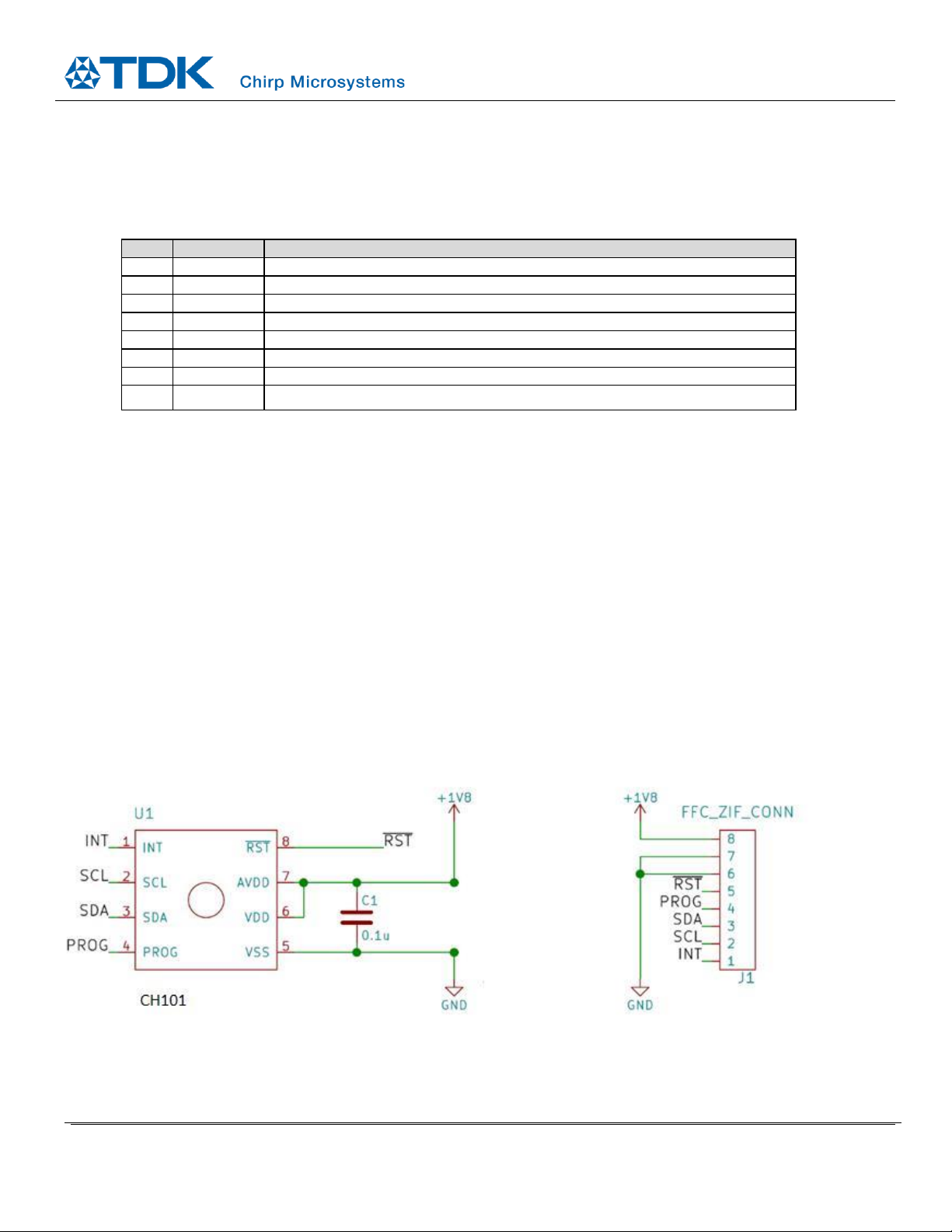
2.3 SCHEMATIC....................................................................................................................................................................................4
2.4 BILL OF MATERIALS .........................................................................................................................................................................5
3CONFIGURATION, PROGRAMMING, AND OPERATION...............................................................................................................6
3.1 CONFIGURATION AND PROGRAMMING................................................................................................................................................6
3.2 OPERATION....................................................................................................................................................................................6
4MECHANICAL SPECIFICATIONS...................................................................................................................................................7
5APPLICATIONS ...........................................................................................................................................................................8
5.1 OBJECT DETECTION .........................................................................................................................................................................8
5.2 BEAM PATTERNS.............................................................................................................................................................................8
Sensor Mounting ................................................................................................................................................................8
Beam Pattern ..................................................................................................................................................................... 9
6REVISION HISTORY...................................................................................................................................................................10
Table of Figures
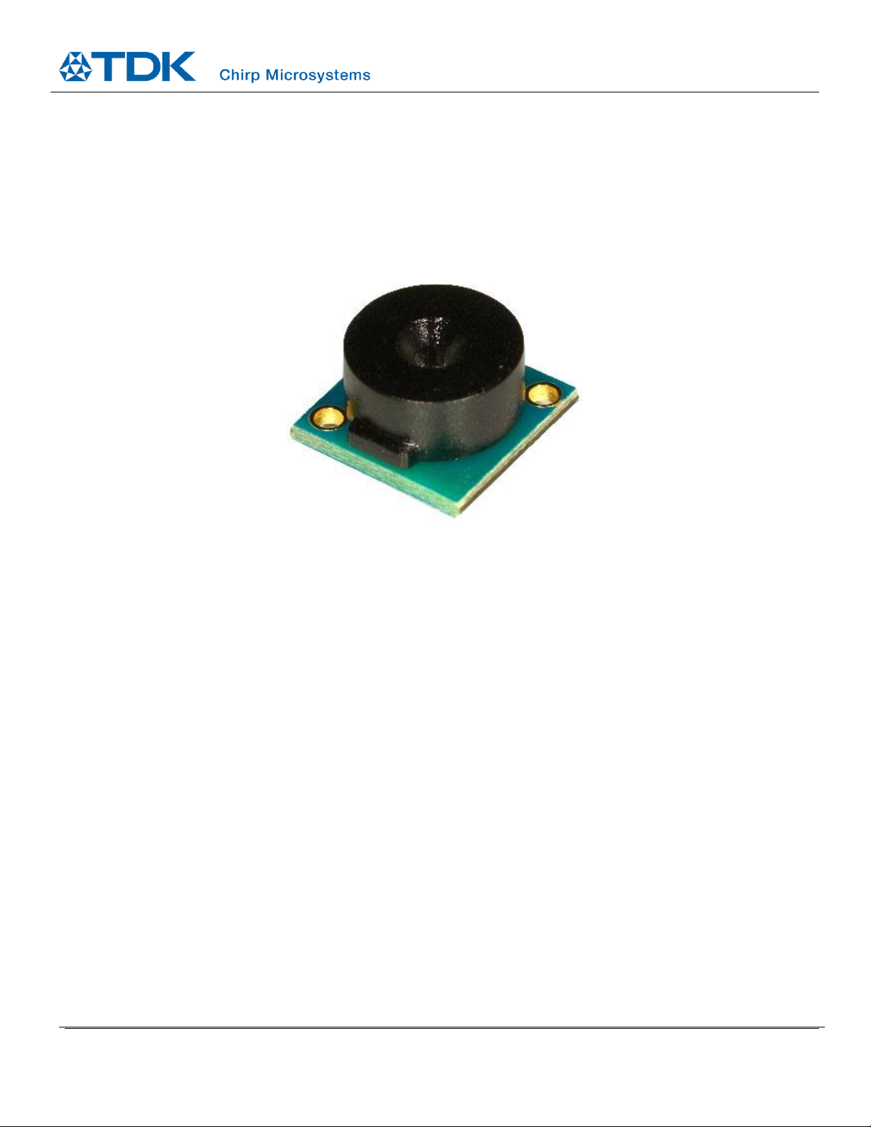
Figure 1-1. View of EV_MOD_CH101-01-02 evaluation module with a particle ingress filter and 45° field-of-view acoustic housing ....3
Figure 2-1. EV_MOD_CH101 Schematic ....................................................................................................................................................4
Figure 2-2. EV_MOD_CH101 Module Connection (EV_MOD_CH101 acoustic port is facing down).........................................................5
Figure 4-1. Dimensions of the EV_MOD_CH101-01-02 assembly .............................................................................................................7
Figure 5-1. Recommended EV_MOD_CH101 module mounting...............................................................................................................8
Figure 5-2. Mount Gap Tolerance..............................................................................................................................................................8
Figure 5-3. EV_MOD_CH101-01-02 Beam pattern ....................................................................................................................................9
List of Tables
Table 1. EV_MOD_CH101 ZIF Connector Pin-Out......................................................................................................................................4
Table 2. Recommended Flat Flex Cable and Connector ............................................................................................................................5
Table 3. Bill of Material..............................................................................................................................................................................5
Table 4. Geometric Dimensions for EV_MOD_CH101-01-02.....................................................................................................................7