AN-000327
Page 7 of 11
Document Number: AN-000327
Revision: 1.0
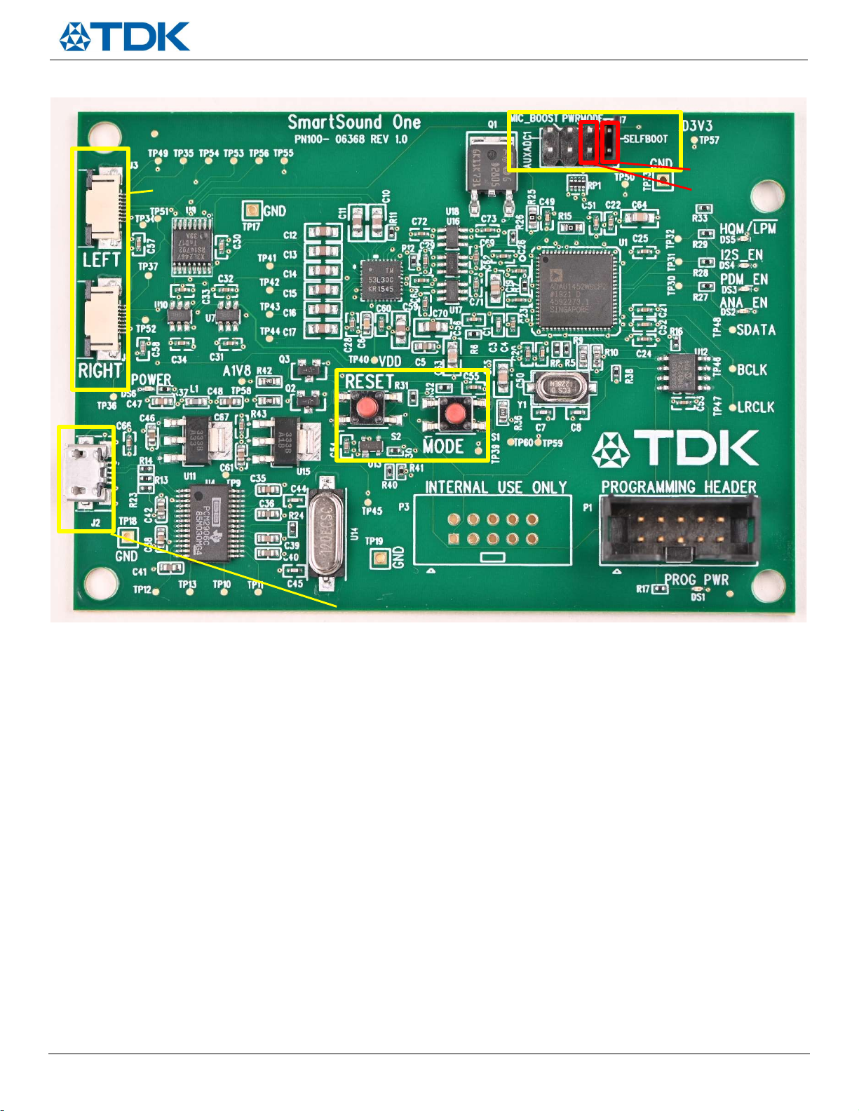
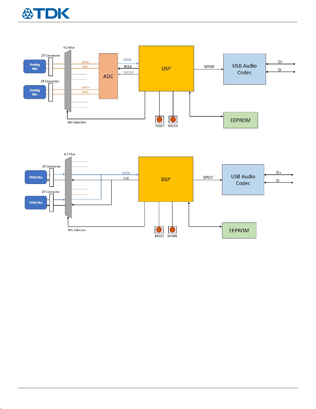
Analog Mode – The ANA_EN LED (DS2) will light up to indicate analog mic connection. The signal from the analog
flex board will be routed to the ADC for conversion to a digital signal which is subsequently routed to the DSP and
USB codec for PC recording/capture
PDM Mode – The PDM_EN LED (DS3) will light up to indicate PDM digital mic connection. The DATA output will be
routed to the DSP and USB codec for PC recording/capture
I2S Mode – The I2S_EN LED (DS4) is disabled on this version of the board
Pressing the mode button will continue to cycle through the modes in the order listed above.
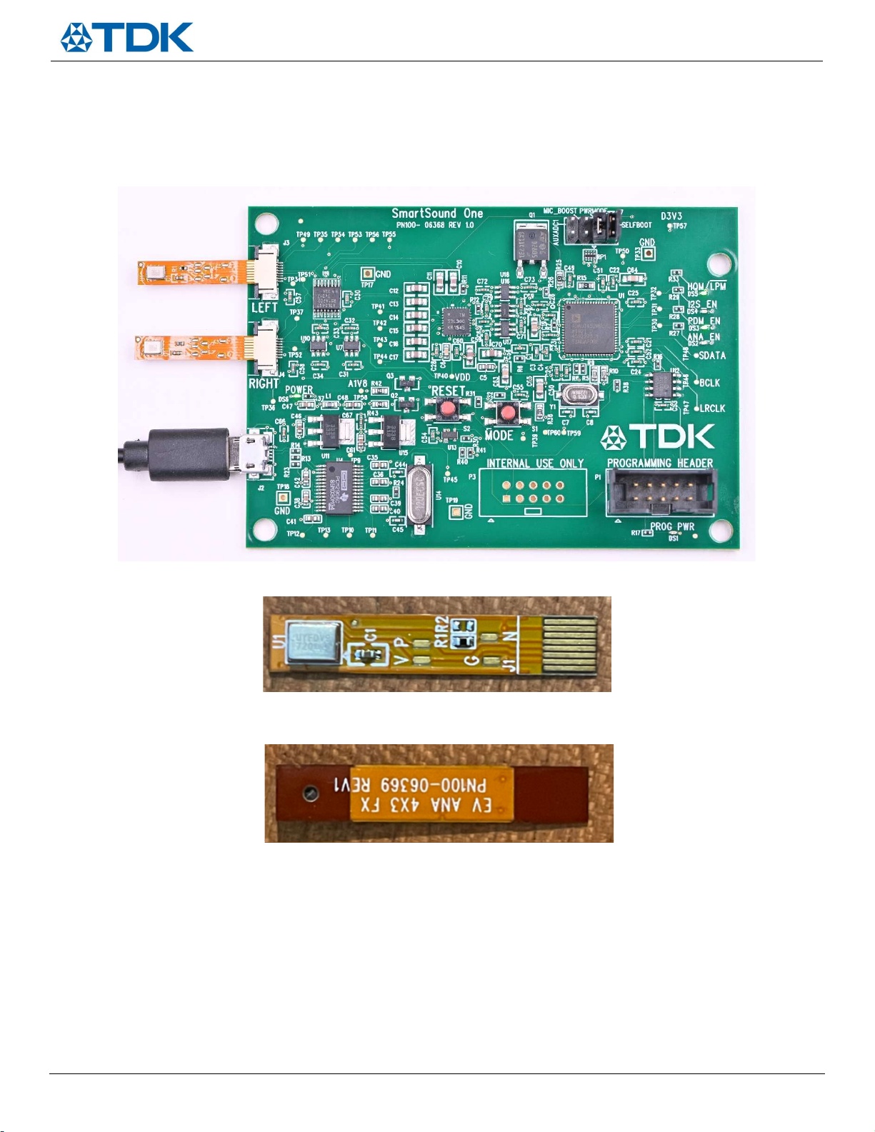
So for example, if the user wants to evaluate a TDK PDM microphone on flex, such as the EV_T5837-FX, then the following steps
should be executed:
1) Power the board up with micro USB cable and verify standby mode (blinking DS5)
2) Press the mode button twice
3) Verify the PDM_EN LED (DS3) is lit
4) Connect EV_T5837-FX flex board to either channel (or into both channels for a stereo input)
5) Record/measure on the host computer
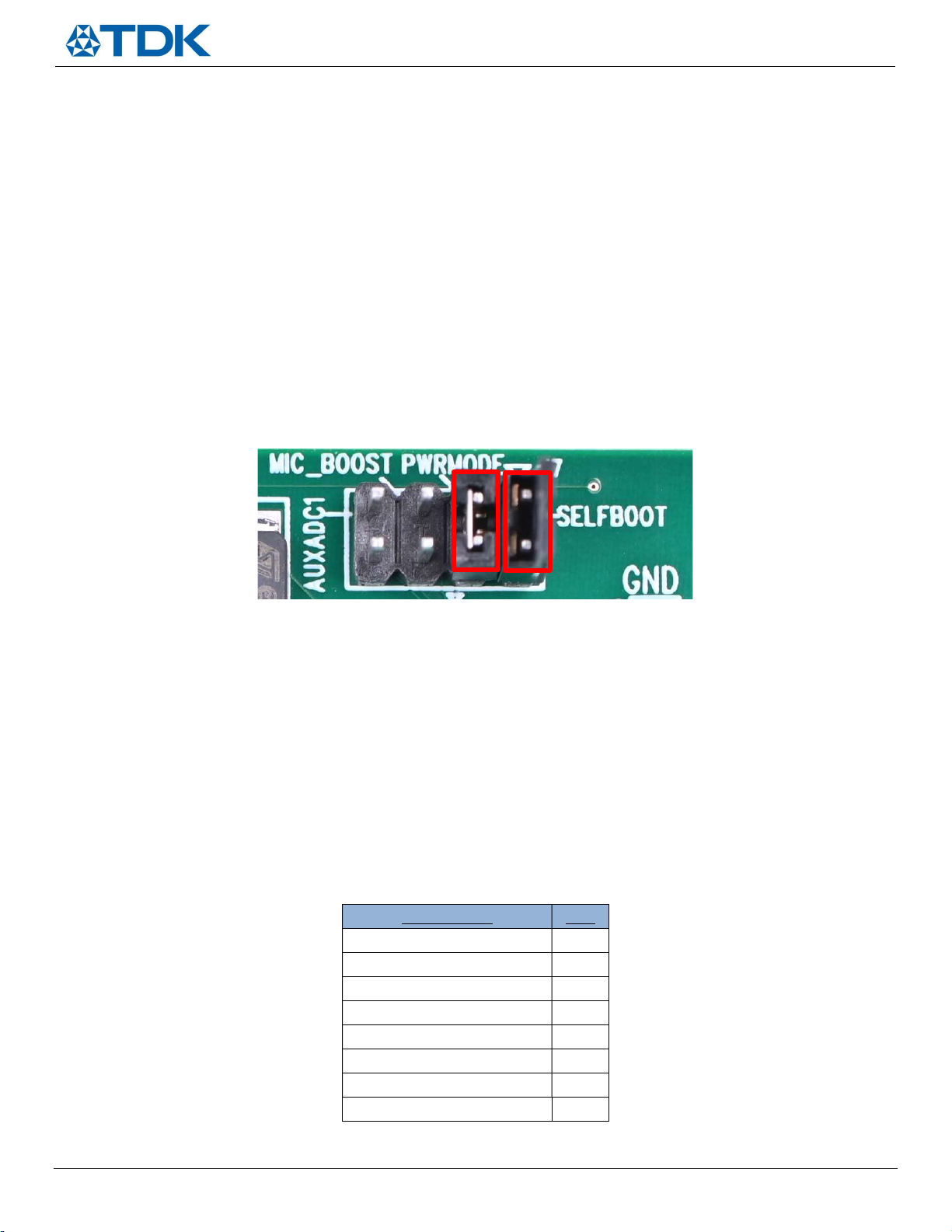
Configuration Header Settings
Figure 9. Configuration header
SmartSound One has four vertical user configurable header pins (reference designator J7) which are shown in Figure 9 and have a
10k pull down resistor by default. Populating the jumper will pull those pins up to 3.3V. The two settings that come pulled up to
3.3V by default are PWRMODE and SELFBOOT, which are highlighted in red in Figure 9. The following provides a description of the
remaining configuration settings (from left to right):
AUXADC1 – Depopulated by default; reserved for future use
MIC_BOOST – Depopulated by default; populating this jumper applies +30dB of digital gain in the DSP for all
microphone signal paths. Users should populate this jumper if they are interested in quick real time monitoring of
the output signal as this will apply the appropriate gain to use and listen as a USB microphone. An external resistor
R can also be populated between these two pins according to the following formula to adjust the digital gain
between 0 and +30dB:
GAIN (dB) = 30*[1-(R/(10K+R))]
Resistor value Gain
0 (populate jumper) +30dB
5k +20dB
10k +15dB
15k +12dB
20k +10dB
40k +6dB
90k +3dB
Open (depopulate jumper) 0dB
Table 1. MIC_BOOST gain settings (typical)