manuals.online logo
Brands
  1. Home
  2. •
  3. Brands
  4. •
  5. TDU
  6. •
  7. Accessories
  8. •
  9. TDU VPS TRAMPOLINE User manual

TDU VPS TRAMPOLINE User manual

1 | P a g e
Thank you for your purchase! We hope
your family Enjoys our products as much as
we do!
Our Patented Ground Level Trampoline
Products have been engineered with safety,
durability, and performance in mind. Please
Read this information thoroughly before
installation, and be sure to visit us online for
more installation tips and videos.
VPS TRAMPOLINE PARTS LIST
•Top Rail Frame Pieces 8
•1 Vented Safety Pad
•1 Jumping mat
•104 springs
•8 Leg extensions
•4 V-shaped Leg Bases
•Leg Screws and Washers (8 each)
•Frame Nuts, bolts, and washers (8 each)
•Spring Tool, screw driver, and wrench
OPTIONAL PARTS LIST:
**if you purchased a TDU Bundle system- you
will also have a lower frame support box with the
following parts included:
•Lower Frame Support Brace (8)
•Nuts, bolts, and washers (16 each)
WARNING: Two adults in good physical condition
are required for the following assembly. For your
safety, you should wear gloves. Failure to follow
these instructions and warnings could result in an
injury.
Installation Instructions
1. Lay out all of the Trampoline parts in
groups, as shown below on a clean, level
installation surface. Please Ensure you have
all necessary components by checking the
parts list.
2. Connect the 8 Top rail frame pieces
together, and secure them with the provided
frame nuts, bolts, and washers. (See figure 3)
2 | P a g e
Figure 3
3. Once the Top Rail Frame Pieces are secured,
insert the Leg Extension Pieces into the top
rail frame neck joints.
**NOTE: Ensure that the Leg Extension pieces are
inserted with the hole for the Leg Screws at the
bottom, facing inside (towards the center of the
Trampoline).
4. Insert the V-shaped Leg bases into the
leg extension poles and secure them with
the Provided Leg Bolts and washers.
**If you purchased the VPS Trampoline to
use above ground –skip to step 9.
If you purchased the in-ground bundle-
proceed to step 5 once all v-shaped leg bases
are secured.
5. Locate the 8 Lower Frame support
braces and lay them out around the
trampoline frame. Place each support
brace between the legs of trampolines-
ensuring the holes line up with the pre-
drilled holes on the v-shaped leg bases.
3 | P a g e
**TIP: The 8 lower frame pieces have different angles on the
clamp section that lines up with the Pilot holes- If the holes aren’t
lining up flip the lower frame brace around or use a different lower
frame piece for that section.
6. With the Entire frame ready to attach the
retaining wall system- un-box the Vented
safety pad, and remove the buckle straps
from the vented pad clips. You will need to
install the receiving end of the buckle clips
onto the frame of the Trampoline prior to
installing the retaining wall system.
**TIP: wrap the strap around the frame to the left of
each leg joint- buckle facing towards the interior of
the trampoline- fed through the buckle section, and
down through the place buckle.
7. At this point refer to the TDU retaining
wall instructions to attach the retaining
wall of the complete bundle system.
**TIP: additional video and installation tips or
images are available online- and additional
instructions are available to download.
8. Once you have completed the TDU retaining
wall installation and backfill- your retaining
wall system should be installed level, and
properly backfilled, and you are now ready
to complete the Trampoline installation.
Installation of the Jumping mat and springs-
9. Start by laying out the jumping mat and
connecting it to the frame of the
Trampoline by installing 1 spring every
5th hole until you have completed the
circle.
4 | P a g e
10. Once you have secured the jumping mat
with a spring spaced out every 5th hole,
start again by placing a spring to the
right of each of the 1st round of springs.
** Continue this process until all springs are
attached.
**TIP: This process is necessary to ensure you do
not overstretch the springs during installation.
11. With the springs installed- you are ready
for the installation of the Vented Safety
pad beginning with step 12.
**Note: If you have purchased our optional
Enclosure Net system- you will at this point begin
installation of the Net base poles onto the frame of
the Trampoline prior to moving on to step 12.
12. Begin by laying out the vented safety
pad on top of the springs of the
Trampoline. Line up the receiving
buckle on the pad with the previously
installed buckle clip on the frame (from
step 6) and lift the pad to locate and
remove a spring that lines up with the
front and center Spring loops- thread the
spring through the loops and re-secure to
the frame.
Complete this process for each pad section.
**Note: There are 8 front loops, and 8 rear loops to
thread springs through.
13. With all the spring loops secured- you
are now ready to finish the installation
by clicking the pad buckle together at all
8 sections.
5 | P a g e
©2017 Trampolines Down Under
VPS TRAMPOLINE INSTRUCTIONS
1584S. 580 E.
American Fork, UT 84003
www.trampolinesdownunder.com
[email protected]

Popular Accessories manuals by other brands

Accutrol ZPS-H quick start guide

Accutrol

Accutrol ZPS-H quick start guide

Siemens SITRANS WS300 operating instructions

Siemens

Siemens SITRANS WS300 operating instructions

Ubiquiti mFi-MSW quick start guide

Ubiquiti

Ubiquiti mFi-MSW quick start guide

Baseus PPCXW10 user manual

Baseus

Baseus PPCXW10 user manual

Novalynx 200-WS-01B user manual

Novalynx

Novalynx 200-WS-01B user manual

Philips HR 2577 user manual

Philips

Philips HR 2577 user manual

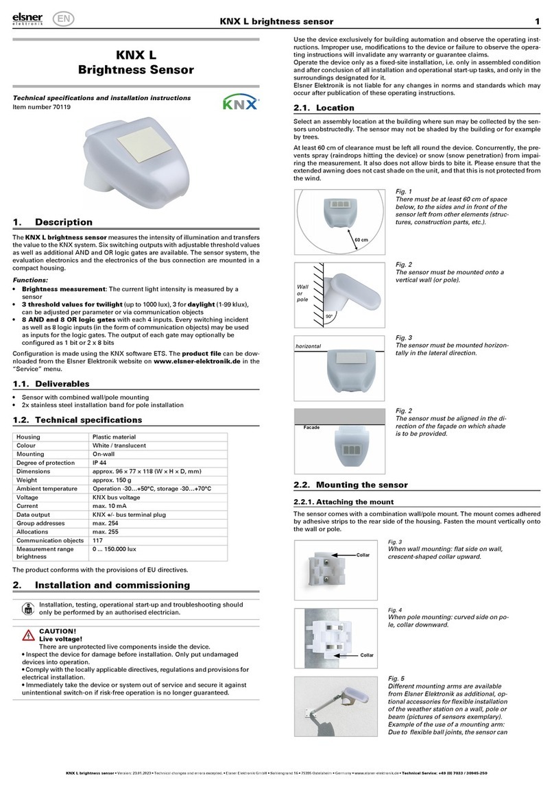
elsner elektronik KNX L Technical specifications and installation instructions

elsner elektronik

elsner elektronik KNX L Technical specifications and installation instructions

DAVIS Vantage Pro2 Updater installation manual

DAVIS

DAVIS Vantage Pro2 Updater installation manual

PCB Piezotronics IMI Sensors CS640B92 Installation and operating manual

PCB Piezotronics

PCB Piezotronics IMI Sensors CS640B92 Installation and operating manual

Xylem YSI ViSolid 700 IQ operating manual

Xylem

Xylem YSI ViSolid 700 IQ operating manual

Lightolier AF2FR specification

Lightolier

Lightolier AF2FR specification

DuroZone MB Series Multi-Blade Damper installation instructions

DuroZone

DuroZone MB Series Multi-Blade Damper installation instructions

EluneVision Luna user manual

EluneVision

EluneVision Luna user manual

CrankShooter Pro Black quick start guide

CrankShooter

CrankShooter Pro Black quick start guide

Waterra WS-2 owner's manual

Waterra

Waterra WS-2 owner's manual

Simon 1B quick start guide

Simon

Simon 1B quick start guide

NeuLog NUL-211 quick start guide

NeuLog

NeuLog NUL-211 quick start guide

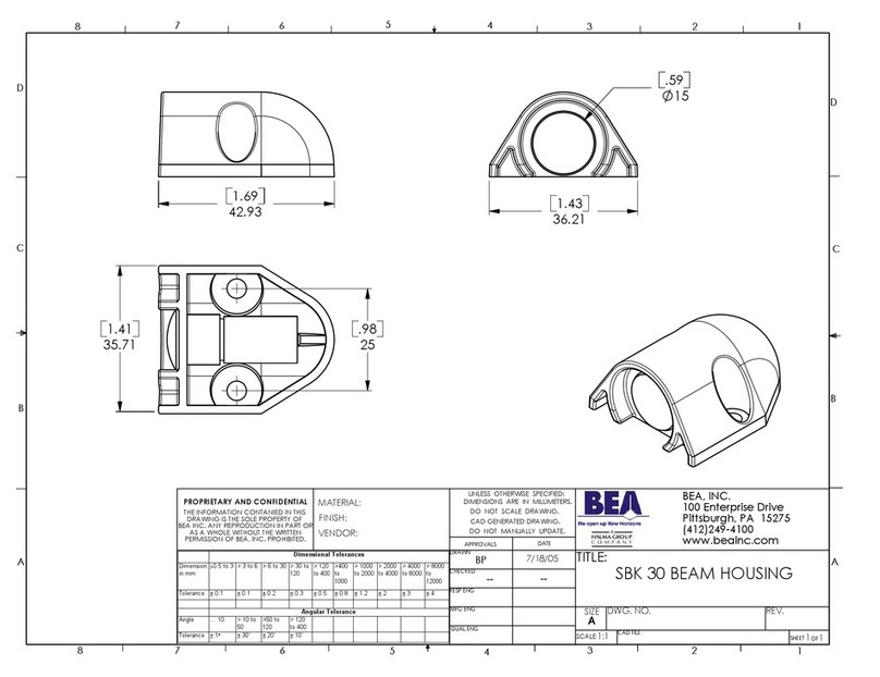
BEA SBK 30 Dimensions

BEA

BEA SBK 30 Dimensions

manuals.online logo
manuals.online logoBrands
  • About & Mission
  • Contact us
  • Privacy Policy
  • Terms and Conditions

Copyright 2025 Manuals.Online. All Rights Reserved.