manuals.online logo
Brands
  1. Home
  2. •
  3. Brands
  4. •
  5. elsner elektronik
  6. •
  7. Accessories
  8. •
  9. elsner elektronik KNX L User manual

elsner elektronik KNX L User manual

KNX L brightness sensor 1
KNX L brightness sensor • Version: 23.01.2023 • Technical changes and errors excepted. • Elsner Elektronik GmbH • Sohlengrund 16 • 75395 Ostelsheim • Germany • www.elsner-elektronik.de • Technical Service: +49 (0) 7033 / 30945-250
EN
KNX L
Brightness Sensor
Technical specifications and installation instructions
Item number 70119
1. Description
The KNX L brightness sensor measures the intensity of illumination and transfers
the value to the KNX system. Six switching outputs with adjustable threshold values
as well as additional AND and OR logic gates are available. The sensor system, the
evaluation electronics and the electronics of the bus connection are mounted in a
compact housing.
Functions:
•Brightness measurement: The current light intensity is measured by a
sensor
•3 threshold values for twilight (up to 1000 lux), 3 for daylight (1-99 klux),
can be adjusted per parameter or via communication objects
•8 AND and 8 OR logic gates with each 4 inputs. Every switching incident
as well as 8 logic inputs (in the form of communication objects) may be used
as inputs for the logic gates. The output of each gate may optionally be
configured as 1 bit or 2 x 8 bits
Configuration is made using the KNX software ETS. The product file can be dow-
nloaded from the Elsner Elektronik website on www.elsner-elektronik.de in the
“Service” menu.
1.1. Deliverables
• Sensor with combined wall/pole mounting
• 2x stainless steel installation band for pole installation
1.2. Technical specifications
The product conforms with the provisions of EU directives.
2. Installation and commissioning
Installation, testing, operational start-up and troubleshooting should
only be performed by an authorised electrician.
CAUTION!
Live voltage!
There are unprotected live components inside the device.
• Inspect the device for damage before installation. Only put undamaged
devices into operation.
• Comply with the locally applicable directives, regulations and provisions for
electrical installation.
• Immediately take the device or system out of service and secure it against
unintentional switch-on if risk-free operation is no longer guaranteed.
Use the device exclusively for building automation and observe the operating inst-
ructions. Improper use, modifications to the device or failure to observe the opera-
ting instructions will invalidate any warranty or guarantee claims.
Operate the device only as a fixed-site installation, i.e. only in assembled condition
and after conclusion of all installation and operational start-up tasks, and only in the
surroundings designated for it.
Elsner Elektronik is not liable for any changes in norms and standards which may
occur after publication of these operating instructions.
2.1. Location
Select an assembly location at the building where sun may be collected by the sen-
sors unobstructedly. The sensor may not be shaded by the building or for example
by trees.
At least 60 cm of clearance must be left all round the device. Concurrently, the pre-
vents spray (raindrops hitting the device) or snow (snow penetration) from impai-
ring the measurement. It also does not allow birds to bite it. Please ensure that the
extended awning does not cast shade on the unit, and that this is not protected from
the wind.
2.2. Mounting the sensor
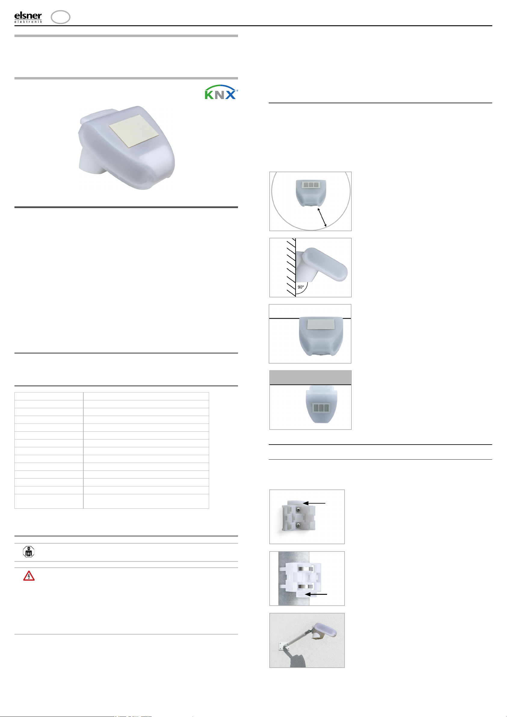
2.2.1. Attaching the mount
The sensor comes with a combination wall/pole mount. The mount comes adhered
by adhesive strips to the rear side of the housing. Fasten the mount vertically onto
the wall or pole.
Housing Plastic material
Colour White / translucent
Mounting On-wall
Degree of protection IP 44
Dimensions approx. 96 × 77 × 118 (W × H × D, mm)
Weight approx. 150 g
Ambient temperature Operation -30…+50°C, storage -30…+70°C
Voltage KNX bus voltage
Current max. 10 mA
Data output KNX +/- bus terminal plug
Group addresses max. 254
Allocations max. 255
Communication objects 117
Measurement range
brightness
0 ... 150.000 lux
Fig. 1
There must be at least 60 cm of space
below, to the sides and in front of the
sensor left from other elements (struc-
tures, construction parts, etc.).
60 cm
Fig. 2
The sensor must be mounted onto a
vertical wall (or pole).
Wall
or
pole
Fig. 3
The sensor must be mounted horizon-
tally in the lateral direction.
horizontal
Fig. 2
The sensor must be aligned in the di-
rection of the façade on which shade
is to be provided.
Facade
Fig. 3
When wall mounting: flat side on wall,
crescent-shaped collar upward.
Collar
Fig. 4
When pole mounting: curved side on po-
le, collar downward.
Collar
Fig. 5
Different mounting arms are available
from Elsner Elektronik as additional, op-
tional accessories for flexible installation
of the weather station on a wall, pole or
beam (pictures of sensors exemplary).
Example of the use of a mounting arm:
Due to flexible ball joints, the sensor can
KNX L brightness sensor 2
KNX L brightness sensor • Version: 23.01.2023 • Technical changes and errors excepted. • Elsner Elektronik GmbH • Sohlengrund 16 • 75395 Ostelsheim • Germany • www.elsner-elektronik.de • Technical Service: +49 (0) 7033 / 30945-250
2.2.2. View of rear side and drill hole plan
2.2.3. Preparing the sensor
The sensor cover snaps in on the left and right along the bottom edge (see Fig.). Re-
move the cover.
Push the bus connection cable through the rubber seal on the bottom of the sensor
and connect bus +/- to the provided clamps.
2.2.4. PCB layout
2.2.5. Mounting the sensor
Close the housing by putting the cover back over the bottom part. The cover must
snap in on the left and right with a definite “click”.
To remove it, the sensor can be simply pulled upwards out of the mount, against the
resistance of the fastening.
2.3. Notes on mounting and commissioning
Do not open the device if water (rain) might ingress: even some drops might dama-
ge the electronic system.
After the bus voltage has been applied, the device will enter an initialisation phase
lasting a few seconds. During this phase no information can be received or sent via
the bus.
3. Addressing of the device at the bus
The device is supplied with the bus address 15.15.255. You can program another ad-
dress into the ETS by overwriting the 15.15.255 address or by teaching via the pro-
gramming key on the circuit board inside the housing.
4. Maintenance
WARNING!
Risk of injury caused by components moved automatically!
The automatic control can start system components and place people in
danger.
• Always isolate the device from the mains for servicing and cleaning.
The device must regularly be checked for dirt twice a year and cleaned if necessary.
In case of severe dirt, the sensor may not work properly anymore.
ATTENTION
The device can be damaged if water penetrates the housing.
• Do not clean with high pressure cleaners or steam jets.
5. Disposal
After use, the device must be disposed of in accordance with the legal regulations.
Do not dispose of it with the household waste!
Fig. 6
Example use of the hinge arm mounting:
With the hinge arm mounting, the weat-
her station projects from beneath the
roof overhang. Sun, wind and precipita-
tion can act upon the sensors without
hindrance.
Fig. 7
Example use of the hinge arm mounting:
Fitting to a pole with worm drive hose
clips
Langloch 7,5 x 5 mm
Fig. 8 a+b
Drill hole plan
Dimensions of rear side
of housing with bra-
cket. Subject to change
for technical enhance-
ment.
Fig. 9
1 Cover Snaps
2 Bottom part of housing
1
2
Unsnap cover and
remove upwards
Fig. 10
1 Slot for KNX clamp +/-
2 Programming LED
3 Programming pushbutton
for the teach-in of the de-
vice
3
2
1
Fig. 11
Make sure the cover and bottom part
are properly snapped together! This
picture is looking at the closed sensor
from underneath.
Fastening
Fig. 12
Push the housing from above into the
fastened mount. The bumps on the
mount must snap into the rails in the
housing.
Fig. 13
After installation, remove the "distan-
ce" sticker on the top of the cover.

Other manuals for KNX L

1

This manual suits for next models

1

Other elsner elektronik Accessories manuals

elsner elektronik KNX LW sl User manual

elsner elektronik

elsner elektronik KNX LW sl User manual

elsner elektronik SO250-UI User manual

elsner elektronik

elsner elektronik SO250-UI User manual

elsner elektronik KNX W sl Guide

elsner elektronik

elsner elektronik KNX W sl Guide

elsner elektronik KNX AQS/TH-B-UP User manual

elsner elektronik

elsner elektronik KNX AQS/TH-B-UP User manual

elsner elektronik KNX AQS TH-B-UP Guide

elsner elektronik

elsner elektronik KNX AQS TH-B-UP Guide

elsner elektronik KNX VOC/TH-UP Touch User manual

elsner elektronik

elsner elektronik KNX VOC/TH-UP Touch User manual

elsner elektronik R 24 V User manual

elsner elektronik

elsner elektronik R 24 V User manual

elsner elektronik KNX RW sl User manual

elsner elektronik

elsner elektronik KNX RW sl User manual

elsner elektronik KNX T-L-Pr-UP Touch Guide

elsner elektronik

elsner elektronik KNX T-L-Pr-UP Touch Guide

elsner elektronik AQS/TH PF User manual

elsner elektronik

elsner elektronik AQS/TH PF User manual

elsner elektronik Sewi KNX L Guide

elsner elektronik

elsner elektronik Sewi KNX L Guide

elsner elektronik KNX VOC/TH-UP Touch CH User manual

elsner elektronik

elsner elektronik KNX VOC/TH-UP Touch CH User manual

elsner elektronik Intra-Sewi KNX T Guide

elsner elektronik

elsner elektronik Intra-Sewi KNX T Guide

elsner elektronik KNX RW User manual

elsner elektronik

elsner elektronik KNX RW User manual

elsner elektronik KNX R Guide

elsner elektronik

elsner elektronik KNX R Guide

elsner elektronik WGTH-UP User manual

elsner elektronik

elsner elektronik WGTH-UP User manual

elsner elektronik KNX B8-TH Guide

elsner elektronik

elsner elektronik KNX B8-TH Guide

elsner elektronik WGTH-UP User manual

elsner elektronik

elsner elektronik WGTH-UP User manual

elsner elektronik WG AQS/TH-UP User manual

elsner elektronik

elsner elektronik WG AQS/TH-UP User manual

elsner elektronik KNX LW 70128 User manual

elsner elektronik

elsner elektronik KNX LW 70128 User manual

elsner elektronik Vari KNX 3L-TH-D GPS User manual

elsner elektronik

elsner elektronik Vari KNX 3L-TH-D GPS User manual

elsner elektronik KNX W Series Guide

elsner elektronik

elsner elektronik KNX W Series Guide

elsner elektronik KNX AQS/TH-B-UP User manual

elsner elektronik

elsner elektronik KNX AQS/TH-B-UP User manual

elsner elektronik WG AQS/TH gl User manual

elsner elektronik

elsner elektronik WG AQS/TH gl User manual

Popular Accessories manuals by other brands

WIKA MH-3 operating instructions

WIKA

WIKA MH-3 operating instructions

Amphenol Temposonics E-Series Operation manual

Amphenol

Amphenol Temposonics E-Series Operation manual

Elko iNELS Air AirCFS-100NB manual

Elko

Elko iNELS Air AirCFS-100NB manual

GEZE GC 342 Installation and operating instructions

GEZE

GEZE GC 342 Installation and operating instructions

CAS CI-502A owner's manual

CAS

CAS CI-502A owner's manual

iB COLUMBO user manual

iB

iB COLUMBO user manual

Eaton Cutler-Hammer iProx Series Technical data

Eaton

Eaton Cutler-Hammer iProx Series Technical data

Eaton CurrentWatch EDC Series Instruction leaflet

Eaton

Eaton CurrentWatch EDC Series Instruction leaflet

Deif WSS 750 user manual

Deif

Deif WSS 750 user manual

Rice Lake IQ plus 210 installation manual

Rice Lake

Rice Lake IQ plus 210 installation manual

Technoton DUT-E A5 installation manual

Technoton

Technoton DUT-E A5 installation manual

IDW G-Series instruction manual

IDW

IDW G-Series instruction manual

Trifo 11 instructions

Trifo

Trifo 11 instructions

Intertek Power Fist user manual

Intertek

Intertek Power Fist user manual

REMOVU P1 user manual

REMOVU

REMOVU P1 user manual

Faudi AFGUARD AFG Series operating instructions

Faudi

Faudi AFGUARD AFG Series operating instructions

Shel lab SCO6AD-2 Installation & operation manual

Shel lab

Shel lab SCO6AD-2 Installation & operation manual

Byron BY112 Installation and operation instruction

Byron

Byron BY112 Installation and operation instruction

manuals.online logo
manuals.online logoBrands
  • About & Mission
  • Contact us
  • Privacy Policy
  • Terms and Conditions

Copyright 2025 Manuals.Online. All Rights Reserved.