Novalynx 200-WS-01B User manual
200-WS-21-A
User Manual
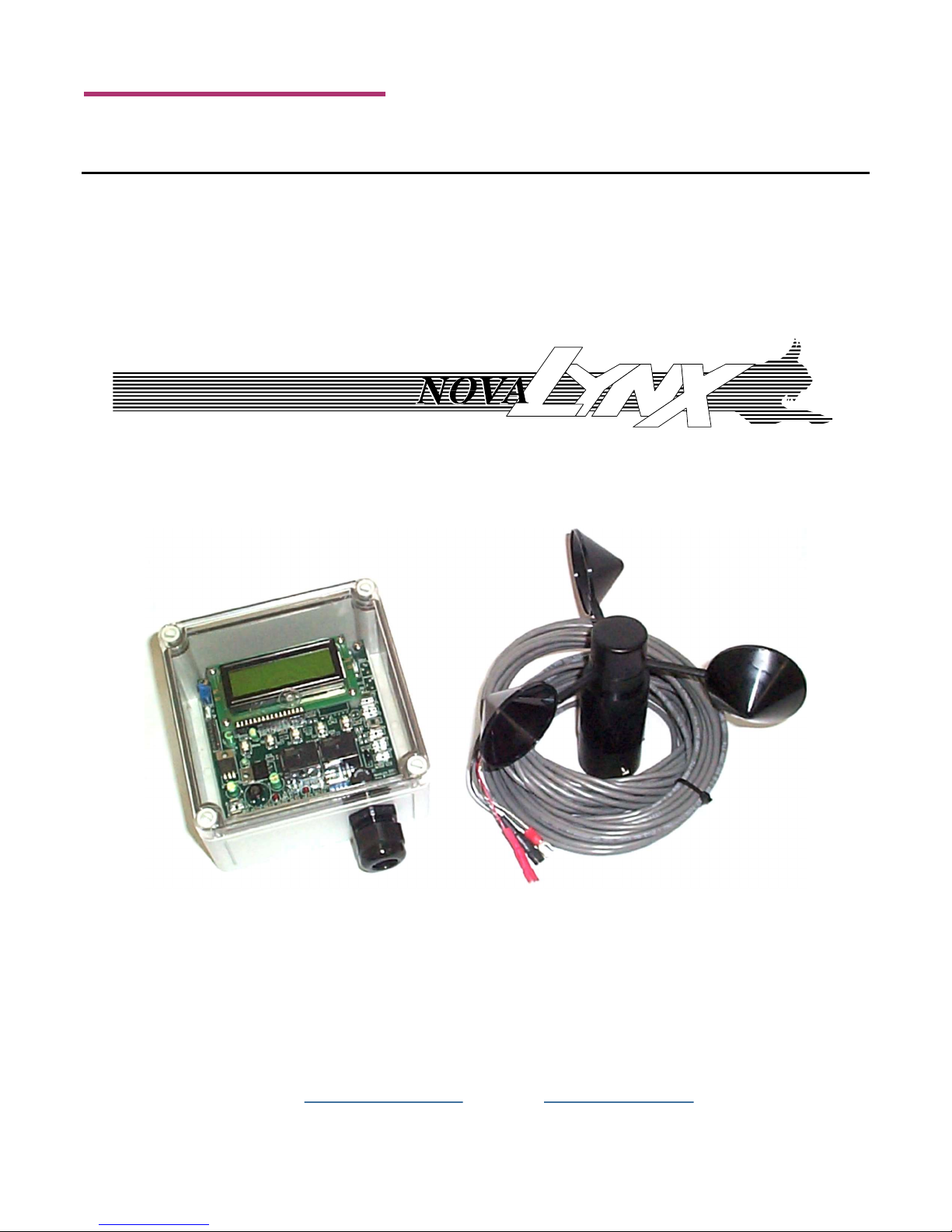
Dual Set Point Wind Alarm
Phone (530) 823-7185 USA Toll Free (800) 321-3577 Fax (530) 823-8997

NovaLynx Corporation________________________________________________________________________________
200-WS-21-A Page 2 November 2018
Receiving and Unpacking
Carefully unpack all components and compare to the packing list. Notify NovaLynx Corporation
immediately concerning any discrepancy. Inspect equipment to detect any damage that may have
occurred during shipment. In the event of damage, any claim for loss must be filed immediately with
the carrier by the consignee. Damages to equipment sent via Parcel Post or UPS require the consignee
to contact NovaLynx Corporation for instructions.
Returns
If equipment is to be returned to the factory for any reason, call NovaLynx between 8:00 a.m. and 4:00
p.m. Pacific Time to request a Return Authorization Number (RA#). Include with the returned
equipment a description of the problem and the name, address, and daytime phone number of the
sender. Carefully pack the equipment to prevent damage or additional damage during the return
shipment. Call NovaLynx for packing instructions in the case of delicate or sensitive items. If packing
facilities are not available take the equipment to the nearest Post Office, UPS, or other freight service
and obtain assistance with the packaging. Please write the RA# on the outside of the box.
Warranty
NovaLynx Corporation warrants that its products are free from defects in material and workmanship
under normal use and service for a period of one year from the date of shipment from the factory.
NovaLynx Corporation's obligations under this warranty are limited to, at NovaLynx's option: (i)
replacing; or (ii) repairing; any product determined to be defective. In no case shall NovaLynx
Corporation's liability exceed product's original purchase price. This warranty does not apply to any
equipment that has been repaired or altered, except by NovaLynx Corporation, or that has been
subjected to misuse, negligence, or accident. It is expressly agreed that this warranty will be in lieu of
all warranties of fitness and in lieu of the warranty of merchantability.
Address
NovaLynx Corporation
431 Crown Point Circle, Suite 120
Grass Valley, CA 95945-9531 USA
Phone: (530) 823-7185
Fax: (530) 823-8997
Email: nova@novalynx.com
Website: www.novalynx.com
Copyright © 1988-2018 by NovaLynx Corporation

NovaLynx Corporation________________________________________________________________________________
200-WS-21-A Page 3 November 2018
CONTENTS
1 FORWARD ....................................................................................................................................................................... 4
2 INTRODUCTION ............................................................................................................................................................... 4
3 TECHNICAL SPECIFICATION ............................................................................................................................................. 4
4 PRE-INSTALLATION CHECKOUT ....................................................................................................................................... 5
4.1 Power Supply Connection ....................................................................................................................................... 6
4.2 Menu Navigation ..................................................................................................................................................... 6
4.2.1 MENU Button .................................................................................................................................................. 6
4.2.2 UP and DOWN Buttons ................................................................................................................................... 6
4.2.3 CLEAR Button .................................................................................................................................................. 7
4.2.4 GO Button ....................................................................................................................................................... 7
4.3 Programming........................................................................................................................................................... 7
4.4 DIP Switch Settings .................................................................................................................................................. 7
5 ANEMOMETER INSTALLATION ........................................................................................................................................ 8
5.1 Anemometer Siting Considerations ........................................................................................................................ 8
5.2 Anemometer Mounting .......................................................................................................................................... 8
5.3 Cable Installation..................................................................................................................................................... 9
5.4 Anemometer Wire Diagram .................................................................................................................................... 9
5.5 Anemometer Maintenance ..................................................................................................................................... 9
6 WIND ALARM CONTROLLER INSTALLATION ................................................................................................................. 10
6.1 Controller Location ............................................................................................................................................... 10
6.2 Controller Mounting ............................................................................................................................................. 10
7 CONNECTIONS ............................................................................................................................................................... 11
7.1 Anemometer Connection ...................................................................................................................................... 11
7.2 Power Connection ................................................................................................................................................. 11
7.3 Relay Connections ................................................................................................................................................. 12
8 Alarm Functions ............................................................................................................................................................ 12
APPENDIX A ........................................................................................................................................................................... 13

NovaLynx Corporation________________________________________________________________________________
200-WS-21-A Page 4 November 2018
1 FORWARD
Thank you for purchasing NovaLynx products. NovaLynx has been designing and manufacturing
weather instruments since 1988. NovaLynx represents several well-known brands of quality
manufacturers, including Gill Instruments, RM Young, Kipp & Zonen, and Vaisala. It is our hope that our
products will meet all your monitoring requirements.
2 INTRODUCTION
The 200-WS-21-A Dual Set Point Wind Alarm includes a rotating cup style anemometer (200-WS-01B)
and internal alarm buzzer. Two independently controlled relays are provided to operate external
equipment such alarm lights or sirens. The Wind Alarm can function as an irrigation or fountain over-
ride controller.
The back-lit LCD display is easily visible through the transparent cover. With the cover removed the
unit is programmed by push-button controls without the need to connect a computer. DIP switch
settings select the units (mph or kph) and enable/disable the buzzer.
Each alarm channel has three programmable settings:
Delay before Alarm 0-99 seconds above threshold before alarm activation (Default 15 sec)
Alarm Set Point Wind speed threshold for the alarm (Default 15 mph)
Delay after Alarm 0-99 seconds below threshold before alarm de-activation (Default 15 sec)
When in alarm mode, a blinking LED indicates which relay(s) are active. Each relay can be connected in
the normally open or the normally closed mode. It is the responsibility of the installer to properly
insulate any connections to the relay terminals, especially if high voltages are present. It is also
important to provide an earth grounding wire to protect the controller from static discharge,
whether or not the relays are connected.
3 TECHNICAL SPECIFICATION
The anemometer is rated for wind speeds up to 125 miles per hour and has a starting threshold of
approximately 1.2 mile per hour. The Wind Alarm LCD can display speeds up to 99.9 mph, but the
control logic continues to operate above this limit.
The controller requires a nominal 12V ac or dc power supply. The 200-WS21P power pack (sold
separately) is suitable in most applications, and comes with the proper terminals for easy connection.

NovaLynx Corporation________________________________________________________________________________
200-WS-21-A Page 5 November 2018
200-WS-21-A Dual Set Point Controller Specification
Display LCD, 2x16 characters, 3x8 mm character size, backlit
Indicators Power: Green LED, Alarms: Red LEDs
Setup DIP switch: WIND/TEMP, MPH/KPH, DEG F/DEG C, BUZZER/DISABLE
Programming Pushbutton: MENU, UP, DOWN, CLEAR, GO
Connections All user connections 1/4" male spade terminals (connectors supplied)
Relay specifications Form "C" (SPDT) N.O. and N.C. Contact rating: 3A @ 24Vdc / 115 VAC
Alarm ON / OFF delay range
0 to 99 seconds
Timing accuracy ± 2%
Measurement range 0 to 99.9
Integration interval 2 seconds
Input Power Nominal 12V AC or DC, 50 mA maximum
Operating temperature -20°C to +50°C
Mounting Knock-outs in back surface for screw mounting to a panel
Dimensions 5.12 x 6.25 x 2.95 inch (13.0 x 15.9 x 7.5 cm)
Weight / Shipping 1 lbs (0.45 kg) / 2 lbs (0.9 kg)
200-WS-01B Anemometer Specification
Measurement Range 125 mph max (55.88 m/s max)
Speed Threshold 1.2 mph (0.5364 m/s)
Speed Constant 1.25 mph = 1 Hz (0.5588 m/s = 1 Hz)
Accuracy 1 mph (0.4470 m/s) or ±3%
Transducer Type Reed switch, magnet activated
Maximum Rating 10 mA @ 50 V (ac or dc)
Turning Radius 4 inch (10.16 cm)
Cable 40 feet (12 m), 2 conductor, 24 AWG, shielded, spade plug connectors
Mounting 1.07 inch diameter by 0.82 inch socket (27 mm dia x 21 mm)
(fits standard 3/4" IPS pipe)
Dimensions 4.5 H x 8.5 W inches (12 x 22 cm)
Weight / Shipping 1 lbs (0.45 kg) / 2 lbs (0.9 kg)
4 PRE-INSTALLATION CHECKOUT
The controller can be operated before installation to become familiar with the menus and programming
features. You will need a power supply and the Wind Alarm controller. The sensor and relays will not be
connected for these tests.
Other manuals for 200-WS-01B
1
This manual suits for next models
2
Table of contents
Other Novalynx Accessories manuals

Novalynx
Novalynx 200-WS-02E User manual

Novalynx
Novalynx 225-HMP60A User manual

Novalynx
Novalynx 260-2520 User manual

Novalynx
Novalynx 225-WS-32THA User manual

Novalynx
Novalynx 200-WS-04 User manual

Novalynx
Novalynx 255-100 User manual

Novalynx
Novalynx 200-WS-01B User manual

Novalynx
Novalynx 230-600C User manual

Novalynx
Novalynx 200-WS-23 User manual

Novalynx
Novalynx 200-WS-03D User manual


