manuals.online logo
Brands
  1. Home
  2. •
  3. Brands
  4. •
  5. TE Connectivity
  6. •
  7. Relay
  8. •
  9. TE Connectivity SRS-2NO User manual

TE Connectivity SRS-2NO User manual

SRS-2NO QUICK START GUIDE
SRS-2NO/QUICK START GUIDE 1/2
A) PACKAGE CONTENTS - CONTENUTO IMBALLO - CONTENU DE L’EMBALLAGE - PACKUNGSINHALT - CONTENIDO DELEMBALAJE
SRS-2NO Safety Relay module / This quick installation guide
SRS-2NO NC Modulo di sicurezza a relè / La presente guida di installazione
SRS-2NO Module Relais de sécurité / Le présent guide d’installation
SRS-2NO Sicherheitsrelais-Modul / Die vorliegende Installationsanleitung
SRS-2NO Módulo de relé de seguridad / La presente guía de instalación
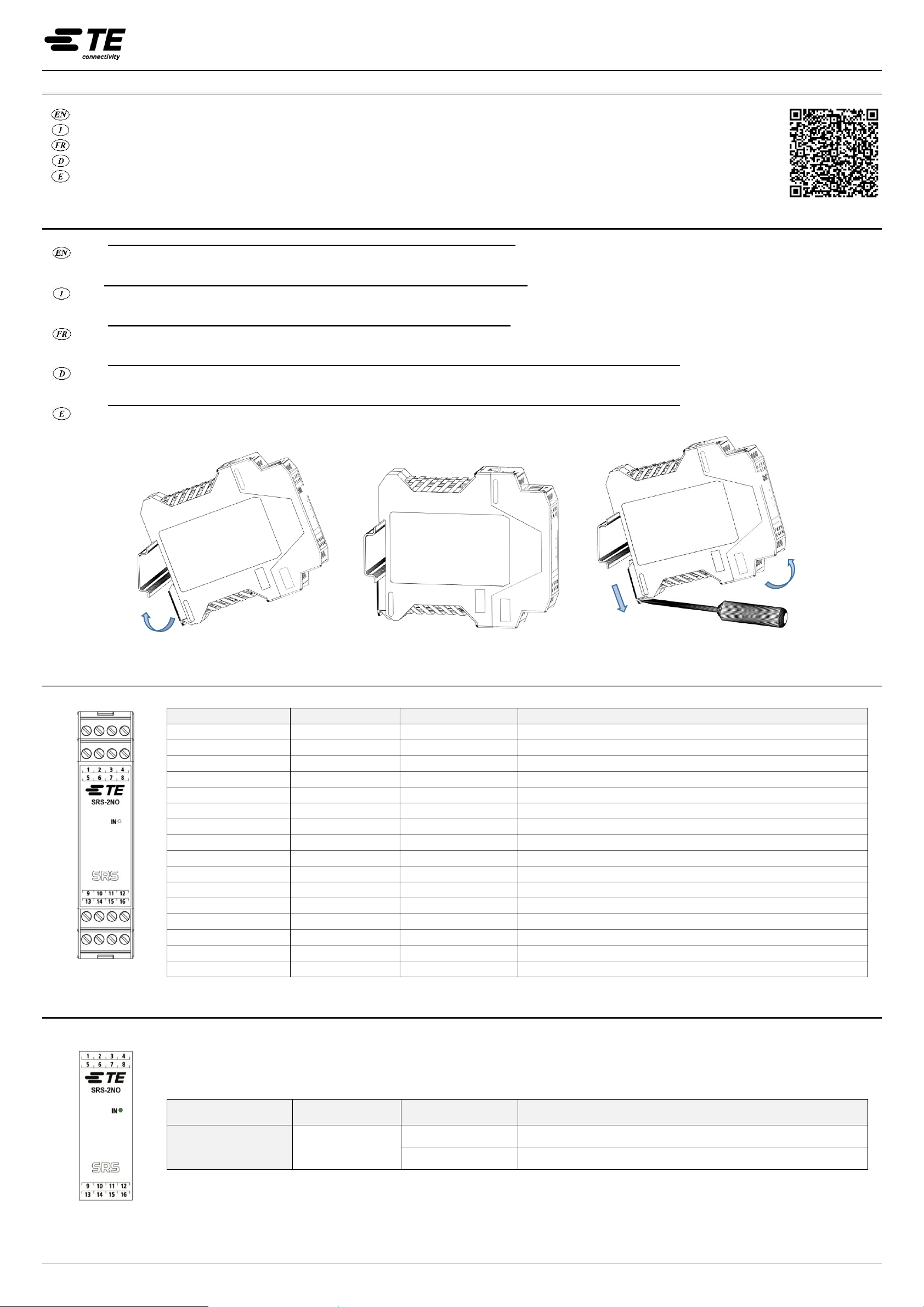
B) MECHANICAL ASSEMBLY - MONTAGGIOMECCANICO - MONTAGE MECANIQUE - BEFESTIGUNG - MONTAJE MECÁNICO
Do not apply power supply before having carried out the following operations.
Fasten the module to the DIN rail. Press the unit gently until you feel it snap into place. To remove the module, use a screwdriver to pull down the locking latch on
the back of the unit; then lift the unit upwards and pull.
Le operazioni che seguono devono essere effettuate in assenza di alimentazione.
Fissare il modulo alla barra DIN premendolo delicatamente fino a sentire lo scatto del bloccaggio. Per rimuovere un modulo è necessario tirare verso il basso
(utilizzando un cacciavite) il gancio di arresto posto sul retro del modulo; sollevare quindi il modulo dal basso e tirare.
Les opérations suivantes doivent être effectuées en l'absence d'alimentation.
Montez le module sur la barre DIN en appuyant doucement sur le module jusqu'à ce que vous entendiez le verrouillage du module. Pour démonter un module,
vous devez tirer vers le bas (à l'aide d'un tournevis) sur le crochet de retenue situé à l'arrière du module, puis soulever le module par le bas et tirer.
Die im Anschluss beschriebenen Vorgänge müssen bei unterbrochener Stromversorgung ausgeführt werden.
Befestigen Sie das Modul auf der DIN-Schiene, indem Sie es vorsichtig nach unten drücken, bis es einrastet. Um ein Modul zu entfernen, müssen Sie
(mit einem Schraubendreher) den Haltehaken auf der Rückseite des Moduls nach unten ziehen, dann das Modul von unten anheben und abziehen.
Die im Anschluss beschriebenen Vorgänge müssen bei unterbrochener Stromversorgung ausgeführt werden.
Enganche el módulo a la barra DIN presionandolo delicadamente hasta que escuche el bloqueo del módulo. Para retirar un módulo debe tirar hacia abajo (con un
destornillador) del gancho de retención en la parte posterior del módulo, luego levante el módulo por la parte inferior y tire.
Figure 1 –Mechanical assembly-disassembly / Montaggio-smontaggio meccanico
C) TERMINAL BLOCKS OFMODULE / MORSETTIERE DEL MODULO / BORNIERS DU MODULE / ANSCHLUSSKLEMMEN DES MODULS / TERMINALES DEL MÓDULO
Figure 2
TERMINAL NUMBER
SIGNAL NAME
TYPE OF SIGNAL
DESCRIPTION
1
-
-
Not used
2
-
-
Not used
3
-
-
Not used
4
0VDC
-
Power Supply 0VDC
5
INPUT1
Input
Safety input 1
6
INPUT2
Input
Safety input 2
7
K1 K2 FBK IN
Input
Feedback K1 K2 Input
8
K1 K2 FBK OUT
Output
Feedback K1 K2 Output
9
-
-
Not used
10
-
-
Not used
11
B NO1
Output
Safety relay B, contact 1 (N.O.)
12
B NO2
Output
Safety relay B, contact 2 (N.O.)
13
-
-
Not used
14
-
-
Not used
15
A NO1
Output
Safety relay A, contact 1 (N.O.)
16
A NO2
Output
Safety relay A, contact 2 (N.O.)
Table 1 –Terminal blocks / Morsettiere
D) STATUS INDICATORS / SEGNALAZIONI / INDICATEURS / STATUSANZEIGEN / INDICADORES DE ESTADO
Figure 3
LED
COLOR
STATUS/COLOR
CONDITION
IN
Green
ON
ON with input activated
OFF
OFF with input not activated
Table 2 –Status Indicators / Segnalazioni
MANUAL
SRS-2NO QUICK START GUIDE
SRS-2NO/QUICK START GUIDE 2/2
E) WIRING DIAGRAMS - SCHEMI DI CONNESSIONE - SCHÉMAS ÉLECTRIQUES - SCHALTPLÄNE - ESQUEMAS DE CONEXIÓN
Example of connection of the SRS-2NO module
with SLC4 safety light curtain in AUTOMATIC operatione mode
Figure 4
For a correct and safe installation and operation of themodule, it is NECESSARY to consult the user manual.
Refer to the manual for details of wiring in the different modes of operation. Other conditions or limitations for use are available in the manual.
➔The safety values and technical data are fully contained in the manual.
Per installare e utilizzarein modo corretto e sicuro il modulo, è NECESSARIOconsultare ilmanuale.
Consultare il manuale per il dettagliodei cablaggi nei diversi modi di funzionamento. Altre condizioni o limitazioni d’uso sono presenti integralmente sul manuale.
➔I valori di sicurezza e i dati tecnici sono contenute integralmente nel manuale.
Pour installer et utiliser correctement et en sécurité le module, il est NECESSAIRE de consulter le manuel d’instruction.
Consultez le manuel pour savoir comment s'effectue le câblage dans les différents modes de fonctionnement. D'autres conditions ou limitations d'utilisation figurent dans le manuel
dans son intégralité.
➔Les valeurs de sécurité et les caractéristiques techniquessont contenues dans le manuel dans son intégralité.
Um das Modul richtig und sicher zu installieren undzuverwenden, MÜSSEN Sie das Handbuch zu Rate ziehen.
EinzelheitenzurVerdrahtungindenverschiedenenBetriebsartenfindenSieimHandbuch.Weitere Bedingungen oder Einschränkungen für die Verwendung finden Sie im Handbuch.
➔Die Sicherheitswerte und technischen Daten sind vollständig im Handbuch enthalten.
Para instalar y utilizar el módulo de forma correcta y segura, DEBEconsultarel manual.
Consulte el manual para los detalles de cableado en los diferentes modos de operación. Otras condiciones o limitaciones de uso se encuentran en el manual en su totalidad.
➔Los valores de seguridad y datos técnicos se encuentran en el manual en su totalidad.

Other TE Connectivity Relay manuals

TE Connectivity SRSE-MA-2NO Installation and operating instructions

TE Connectivity

TE Connectivity SRSE-MA-2NO Installation and operating instructions

TE Connectivity PLL/D-100/120 User manual

TE Connectivity

TE Connectivity PLL/D-100/120 User manual

TE Connectivity SRSE-2NO Installation and operating instructions

TE Connectivity

TE Connectivity SRSE-2NO Installation and operating instructions

TE Connectivity SRS4M-2NO User manual

TE Connectivity

TE Connectivity SRS4M-2NO User manual

TE Connectivity SRS-2NO-1NC User manual

TE Connectivity

TE Connectivity SRS-2NO-1NC User manual

Popular Relay manuals by other brands

Entes MCB-8 quick start guide

Entes

Entes MCB-8 quick start guide

Eaton ESR5-VE3-42 manual

Eaton

Eaton ESR5-VE3-42 manual

Vemer CLIP-485 user manual

Vemer

Vemer CLIP-485 user manual

Vega VEGASWING 66 Safety manual

Vega

Vega VEGASWING 66 Safety manual

Omron SYSMAC-SE2 Practices Guide

Omron

Omron SYSMAC-SE2 Practices Guide

Basler BE1-87G instruction manual

Basler

Basler BE1-87G instruction manual

Ampcontrol ELM user manual

Ampcontrol

Ampcontrol ELM user manual

Mikro MK204A user guide

Mikro

Mikro MK204A user guide

Rockwell Automation Guardmaster MSR57P release note

Rockwell Automation

Rockwell Automation Guardmaster MSR57P release note

Pizzato Elettrica CS AR-08 Series manual

Pizzato Elettrica

Pizzato Elettrica CS AR-08 Series manual

ASO Safety Solutions ISK 74-31 operating instructions

ASO Safety Solutions

ASO Safety Solutions ISK 74-31 operating instructions

Hitachi PN-150BE manual

Hitachi

Hitachi PN-150BE manual

Pilz PNOZ X2.1VP operating manual

Pilz

Pilz PNOZ X2.1VP operating manual

GE IFV51AD instructions

GE

GE IFV51AD instructions

IFM Electronic ecomat 200 Monitor AL-3 operating instructions

IFM Electronic

IFM Electronic ecomat 200 Monitor AL-3 operating instructions

Leviton Z-Max Remote Manual addendum

Leviton

Leviton Z-Max Remote Manual addendum

Leviton EnOcean WSPAS-LV4 installation instructions

Leviton

Leviton EnOcean WSPAS-LV4 installation instructions

socomec ATyS 3S operating instructions

socomec

socomec ATyS 3S operating instructions

manuals.online logo
manuals.online logoBrands
  • About & Mission
  • Contact us
  • Privacy Policy
  • Terms and Conditions

Copyright 2025 Manuals.Online. All Rights Reserved.