Teac DW-224E-V Owner's manual

34 sheets in Total
TEAC DW-224E-R93
CD-RW/DVD-ROM DRIVE
HARDWARE SPECIFICATION
Rev. A
7757a

– i –
TABLE OF CONTENTS
Title Page
1. SCOPE ........................................................................................................................................ 1
2. OUTLINE ..................................................................................................................................... 1
3. CONSTRUCTION ........................................................................................................................ 2
3.1 External Construction ........................................................................................................... 2
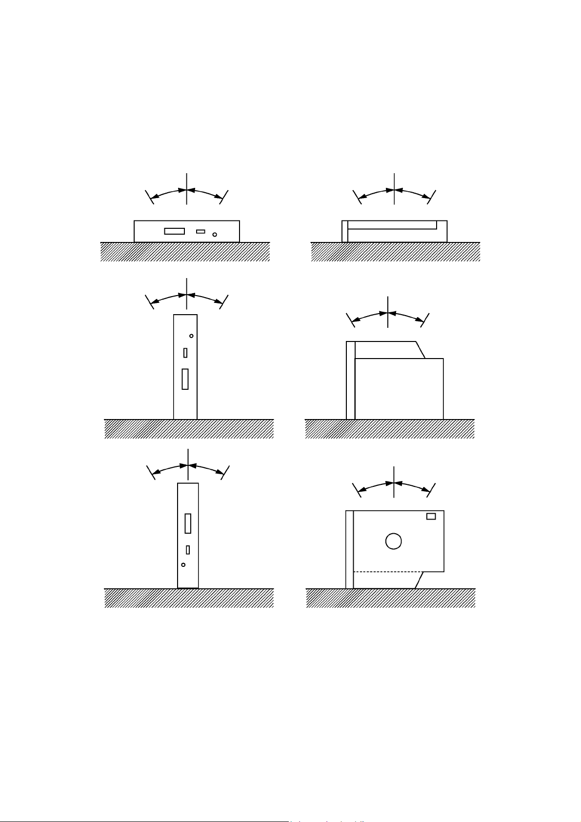
3.2 Installation ............................................................................................................................. 4
4. DISC SPECIFICATION ................................................................................................................ 5
4.1 Applicable Disc Format ........................................................................................................ 5
4.2 Rotational Speed ................................................................................................................... 5
4.3 Data Capacity ........................................................................................................................ 6
4.4 Write methods ....................................................................................................................... 6
4.5 Readable disc ........................................................................................................................ 6
4.6 Recordable Disc (Recording Speed) ................................................................................... 6
5. PERFORMANCE ......................................................................................................................... 7
5.1 Operating Performance ........................................................................................................ 7
5.2 Audio ...................................................................................................................................... 7
5.3 Acoustic Noise ...................................................................................................................... 7
6. ENVIRONMENTAL CONDITIONS .............................................................................................. 8
7. RELIABILITY ............................................................................................................................... 9
8. SAFETY STANDARDS ............................................................................................................... 9
9. FRONT INDICATOR .................................................................................................................... 9
10. DRIVE CONFIGURATION ......................................................................................................... 9
11. INTERFACE CONNECTOR .................................................................................................... 10
12. AUDIO INTERFACE ................................................................................................................ 11
13. POWER INTERFACE .............................................................................................................. 11
14. IDE HARDWARE INTERFACE ............................................................................................... 12
14.1 Outline ................................................................................................................................ 12
14.2 Electrical Characteristics ................................................................................................. 12
14.3 Input/Output Signals ......................................................................................................... 13
14.4 Interface Timing ................................................................................................................ 14
14.5 COMMAND SET ................................................................................................................. 26
14.5.1 ATA COMMAND ........................................................................................................... 26
14.5.2 ATAPI COMMAND ....................................................................................................... 27
15. POWER MANAGEMENT SPECIFICATION ........................................................................... 29
15.1 Power Management Modes .............................................................................................. 29
15.1.1 Transition in power management mode ................................................................... 29
15.2 Active Mode ....................................................................................................................... 30
15.3 Idle Mode ............................................................................................................................ 30
15.4 Standby Mode .................................................................................................................... 31
15.5 Sleep Mode ........................................................................................................................ 31
15.5.1 Tray ejection/insertion in the sleep mode ................................................................. 31
16. OTHERS .................................................................................................................................. 31
16.1 Using the lens cleaner ...................................................................................................... 31
16.2 Safety of Laser Products .................................................................................................. 32

– 1 –
1. SCOPE
This is hardware specification of the TEAC DW-224E-R93 built-in type CD-RW/DVD-ROM drive
(hereinafter referred to as drive). As for the software specification, refer to "DW-224E-C Software
Specification".
2. OUTLINE
The outline of this drive is given in Table 2-1.
(Table 2-1) Outline of the specification
Model name DW-224E-R93
TEAC P/N 1977098-R93
Applicable safety standards UL, CSA, TÜV, CE
Data transfer rate (burst) 33.3MBytes/sec max
Average access time 90msec (CD-ROM)/110msec (DVD-ROM), average by
TEAC standards
Disc speed (24X CAV speed mode) 5,090min-1 (Approx)
Host interface IDE (ATAPI)
Power source +5VDC
Starting time 19sec max
Readable discs CD/CD-ROM (12cm, 8cm)
CD-R (Recorded)
CD-RW (Recorded)
DVD-ROM
DVD-R (Recorded)
DVD-RW (Recorded)
DVD-RAM (Recorded)
DVD+R (Recorded)
DVD+RW (Recorded)
Recordable disc CD-R/RW disc (Refer to item 4.6)
Applicable format CD-DA
CD-ROM Mode 1, Mode 2
CD-ROM XA Mode 2 (Form 1, Form 2)
Photo CD (Single/Multi-session)
Enhanced CD
CD-TEXT
DVD-ROM
DVD-R (General. Authoring)
DVD-Video
DVD-RAM (4.7GB, 2.6GB)
DVD+R/RW (Single/Multi-session, Packet)
Write methods Disc at once, Session at once, Packet write, Track at once
Front bezel Black
Eject button Black
Access indicator Green
Laser class Class 1 laser product

– 2 –
3. CONSTRUCTION
3.1 External Construction
(1) Dimensions
(a) Height : 12.7mm (excluding the front bezel)
(b) Width : 128mm (excluding the front bezel)
(c) Depth : 129.4mm (excluding the eject button)
(2) Mass : 178g or less
(3) Disc clamp system : Ball clamp
(4) Loading : Manual loading using the tray
(5) Ejection
(a) Manual eject using the eject button
(b) Automatically eject using the command
(c) Eject distance : 10mm or more
(6) External view : Refer to Fig. 3.1-1.

– 3 –
(Fig. 3.1-1) External view of the drive
( ± 0.4 )
(Unit : mm)

– 4 –
3.2 Installation
(1) Installation direction : Refer to Fig. 3.2-1
(2) Tilt : Refer to Fig. 3.2-1 below.
(3) Installation method : The fixing holes in the side of the unit are used.
Separate discussions and arrangements are required when the
installation holes are not used.
(Fig. 3.2-1) Tilt of the drive
30° or less 30° or less 30° or less 30° or less
30° or less 30° or less
0° or less 30° or less
30° or less 30° or less
30° or less 0° or less
(a)
(b)
(c)

– 5 –
4. DISC SPECIFICATION
4.1 Applicable Disc Format
• CD-DA
• CD-ROM Mode 1
• CD-ROM XA Mode 2 (Form 1, Form 2)
• Multi-session Photo CD
• CD-I
• Video CD
• Enhanced CD
• CD-TEXT
• DVD-ROM
• DVD-R (General, Authoring)
• DVD-Video
• DVD-RW
• DVD-RAM (4.7GB, 2.6GB)
• DVD+R/RW (Single/Multi-session, Packet)
4.2 Rotational Speed
Refer to Table 4.2-1 for the rotational speed.
(Table 4.2-1) Rotational speed (read mode)
Operation/Disc format Read speed/Disc speed
Idle mode (DVD) 4x CAV 2,297rpm
Idle mode (CD) 10x CAV 2,140rpm
Read (DVD-ROM) 8x CAV 4,594rpm
Read (DVD-Video) 4x CAV 2,297rpm
Read (CD-ROM Model) 24x CAV 5,137rpm
Read (CD-ROM Mode2form2) 20x CAV 4,280rpm
Read (CD-DA) 20x CAV 4,280rpm
Play Audio 4x CLV 856 - 1,984rpm
Mixed (CD-ROM Model and Mode2form2 or CD-DA) 20x CAV 4,280rpm
Mixed (DVD-ROM and DVD-Video) 8x CAV 4,594rpm
CD-RW (Read only operation) 24x CAV 5,137rpm
DVD-R/DVD-RW, DVD+R/DVD+RW 8x CAV 4,594rpm
DVD-RAM (4.7GB) 5x CAV 3,246rpm
DVD-RAM (2.6GB) 2.5x CAV 1,626rpm

– 6 –
4.3 Data Capacity
• 650MB/700MB : CD-ROM Mode 1
: CD-ROM XA Mode 2 Form 1
• 738MB/795MB : CD-ROM XA Mode 2 Form 2
• 74min/79min : CD-DA
• 4.7GB/side : DVD-ROM, DVD-Video, DVD-R, DVD-RW, DVD-RAM,
DVD+R, DVD+RW
• 8.5GB/side : DVD-ROM, DVD-Video (Dual layer)
• 2.6GB/side : DVD-RAM
4.4 Write methods
Disc at once, Track at once, Session at once, and Packet write
4.5 Readable disc
Press CD, Recorded CD-R/RW, Press DVD, Recorded DVD-R, Recorded DVD-RW, Recorded DVD-RAM,
Recorded DVD+R, Recorded DVD+RW
4.6 Recordable Disc (Recording Speed)
Recommended as the recordable disc to be used in this drive is a 79-minute disc for 8x speed manufactured by
Taiyo Yuden Co., Ltd. (TEAC Part No.: T0006613, CD-R80-BULK). The use of other recordable discs is
conditional on mutual understanding between TEAC and specific users.
With the recommended type of discs, the following speeds of recording are available:
4x speed, 10x speed, 16x speed and 24x speed
(Table 4.2-2) Rotational speed (Write mode)
Disc Read speed/ Disc speed
CD-R
24x CAV 5,137rpm
16x CAV 3,425rpm
10x CLV 2,140 - 4,954rpm
4x CLV 856 - 1,984rpm
CD-RW
Multi speed 4x CLV 856 - 1,984rpm
High speed
10x CLV 2,140 - 4,954rpm
10x CAV 2,140rpm
4x CLV 856 - 1,984rpm
Ultra speed 24x CAV 5,137rpm

– 7 –
5. PERFORMANCE
5.1 Operating Performance
(1) Average random access time : 90msec average (CD-ROM, 24x), 110msec average (DVD-ROM, 8x)
(2) Disc speed : Refer to 4.2
(3) Data transfer rate
(a) Read sustained : 1,545 to 3,600kB/sec (CD-ROM model)
4,469 to 10,816kB/sec (DVD-ROM)
(b) Programmed I/O : 16.7MB/sec max (Mode 0 to 4)
(c) Multi-word DMA : 16.7MB/sec max (Mode 0 to 2)
(d) Ultra DMA : 33.3MB/sec max
(4) Starting time
(a) When power is switched on/when disc is loaded
: 19sec max (excluding the multi-session CD)
(b) Return time from the standby mode
: 4sec or less
(5) Data buffer capacity : 2MB
5.2 Audio
(1) Line output
The following specifications apply during audio play.
(a) Number of channels : 2 channels (stereo)
(b) Frequency response : 20 to 20kHz (±3dB)
(c) Dynamic range : 83dB or more (IHF A, 1kHz, LPF 20kHz)
(d) S/N : 85dB or more (IHF A, 1kHz, LPF 20kHz)
(e) Distortion factor : 0.05% or less (1kHz, 20kHz LPF)
(f) Channel separation : 70dB or more (1kHz, 20kHz LPF)
(g) Output level : 0.8Vrms ±3dB (load = 47kΩATT = 0dB)
(h) Muting : each channel independent (using the ATAPI command)
(i) Volume : Software volume using the ATAPI command;
255 steps from volume level 0 to −∞ (infinity) dB; variable for each
channel independently.
5.3 Acoustic Noise
(1) Operating : 45dBA or less (during seek/read/write/Active/Idle, distance 0.5m)
(2) Ejecting : 65dBA or less (distance 0.5m)

– 8 –
6. ENVIRONMENTAL CONDITIONS
The environmental conditions as specified here do not include the environmental conditions of the disc. The
environmental conditions of the disc should follow the specifications of the applicable disc.
(1) Ambient temperature
(a) During operation : 5 to 45°C (Surface temperature on the top cover; 5 to 50°C)
(b) During non-operation : –20 to 60°C
(c) During transportation (packaged)
: –40 to 65°C
(2) Temperature gradient
(a) During operation : 11°C/hour or less (noncondensing)
(b) During non-operation/transportation
: 20°C/hour or less (noncondensing)
(3) Relative humidity
(a) During operation : 8 to 80% (noncondensing)
provided that the maximum wet-bulb temperature is 29.4°C or less.
(b) During non-operation/transportation
: 5 to 95% (noncondensing)
provided that the maximum wet-bulb temperature is 29.4°C or less.
(c) During transportation (packaged)
: 5 to 95% (noncondensing)
provided that the maximum wet-bulb temperature is 29.4°C or less.
(4) Vibrations
(a) During operation:
When installed horizontally: 2.9m/s2(0.3G) or less
When installed vertically : 1.96m/s2(0.2G) or less
provided that the sweep frequency is 5 to 500Hz and sweep rate,
1oct/min.
excepting recording mode.
(b) Transportation (packaged) : 19.6m/s2(2G) or less provided that the sweep frequency is 5 to 500Hz
and sweep rate, 1oct/min.
(5) Shock
(a) During operation (free from malfunction)
When installed horizontally: 68.6m/s2(7G) or less (half-sine shock
pulse; 11msec, intervals; 10sec)
When installed vertically : 49m/s2(5G) or less (half-sine shock pulse;
11msec, intervals; 10sec)
excepting recording mode and CD-DA play mode.
(b) During operation (while the CD-DA is playing)
:19.6m/s
2(2G) or less (half-sine shock pulse; 11msec., intervals; 10sec)
(c) During non-operation/transportation
: 588m/s2(60G) or less (half-sine shock pulse; 11msec)
1,960m/s2(200G) or less (half-sine shock pulse; 2msec)
However, tray ejection is allowed.
(6) Dust : office environment
(7) Cooling : natural air cooling

– 9 –
7. RELIABILITY
(1) Mean time between failures (MTBF)
: 60,000POH or more (the frequency of use should be 10% at normal
temperature and humidity)
(2) Mean time to repair (MTTR) : 30minutes
(3) Loading/ejecting life : 10,000times or more
(4) Power ON/OFF life : 60,000 times or more
(5) Laser diode life : MTTF 9,000 hours (Duty 50% pulse 83mW, 60°C)
(6) Seeking life : 2 × 10⁶ times or more (random access, 25°C, duty; 20% or less)
(7) Error rate
(a) Read error rate
DVD : Once per 1012 bits or less
CD : MODE 1 and MODE 2 (FORM 1) : Once per 1012 bits or less
MODE 2 (FORM 2) and CDDA : Once per 109bits or less
(b) Seek error rate : Once per 106seeks or less
(c) Seek error rate : Once per 106seeks or less
(8) Self-diagnosis
(a) When power is switched ON: Various controllers, ROM, RAM, buffer, ECC circuit, etc.
(b) When disc is inserted : Servo circuit, signal processors, etc.
8. SAFETY STANDARDS
The drive complies with the following safety standards:
(1) UL standard
(2) CSA standard
(3) TÜV standard
(4) CE standard
9. FRONT INDICATOR
(1) Location : Refer to Fig. 3.1-1.
(2) Color : Green
(3) Lighting conditions
(a) Continuous on
• During seek
• Transfer of the read data to the host is under way.
(b) Flashing with a period of 3 second (Duty 50%)
• During write
• While audio is being played
(c) Flashing with a period of 1 second (Duty 50%)
• From POR or tray loading to the end of TOC read (when the disc is present)
• From POR or tray loading to the end of detecting the disc (when the disc is not present). If an error
which is considered to arise from the disc occurs, flashing continues until the disc is ejected. If an error
which seems to rest with the drive’s hardware, flashing continues until the power is switched OFF.
10. DRIVE CONFIGURATION
The setting to master or slave is determined by the −CSEL signal (interface connector 47 pin).
If the −CSEL signal is at low level, the drive is set to the slave, and if it is open or at high level, it is set to the
master.

– 10 –
11. INTERFACE CONNECTOR
(1) Connector on the drive : JAE KX15-50KLDLE or equivalent
(2) Applicable connector on the host : JAE KX14-50K5D1 or equivalent
(3) Pin assignment : Refer to Table 11-1, Fig. 11-1.
(Fig. 11-1) Interface connector assignment
(Table 11-1) Interface connector pin assignment
No. SIGNAL No. SIGNAL
1LOUT2ROUT
3 AGND 4 N.C
5 –RESET 6 DD8
7DD78DD9
9DD610DD10
11 DD5 12 DD11
13 DD4 14 DD12
15 DD3 16 DD13
17 DD2 18 DD14
19 DD1 20 DD15
21 DD0 22 DMARQ
23 GROUND 24 –DIOR (–HDMARDY/HSTROBE)
25 –DIOW (STOP) 26 GROUND
27 IORDY (–DDMARDY/DSTROBE) 28 –DMACK
29 INTRQ 30 –IOCS16
31 DA1 32 –PDIAG (–CBLID)
33DA034DA2
35 –CS0 36 –CS1
37 –DASP 38 +5V
39 +5V 40 +5V
41 +5V 42 +5V
43 GROUND 44 GROUND
45 GROUND 46 GROUND
47 –CSEL 48 GROUND
49 RESERVED 50 RESERVED
Pin No. 1
Pin No. 50

– 11 –
12. AUDIO INTERFACE
(1) LOUT : Line output of the left channel (unbalanced)
(2) ROUT : Line output of the right channel (unbalanced)
(3) AGND : Ground of audio line output.
For the electrical specification of the line output, refer to 5.2.
13. POWER INTERFACE
The following specifications apply to the interface connector terminals of the drive. The power should be
supplied from a power supply unit with reinforced insulation or double insulation.
(1) Allowable supply voltage range
: +5VDC ±5% (4.75 to 5.25V)
There should be no abnormal operations by DC +5V ±10%.
(2) Allowable ripple voltage : 100mVp-p or less, 50 to 20MHz (including the spike noise)
(3) Current consumption : Refer to Table 13-1.
(Table 13-1) Current consumption
Mode Average current max (A) Peak current max (A)
Standby/Sleep 0.025
Write 24x 1.0
Active 0.9
Random access (Duty 100%) 1.2 1.5
During starting/seek 1.5
During eject 1.5
Remarks:
1. The supply voltage should be 5V+5%.
2. For each of the sleep, standby, and active modes, refer to "15. POWER MANAGEMENT
SPECIFICATION".
3. Does not include pulse-like current below 1msec.

– 12 –
14. IDE HARDWARE INTERFACE
14.1 Outline
(1) Applicable standard
ANSI standard : X3T13/1321D (ATA-5)
SFFC : SFF-8020i Rev. 2.6 and SFF-8090v3
14.2 Electrical Characteristics
The following specifications apply to the interface connector terminal for the IDE signal of the drive. The input
signals refer to the signals input to the drive whereas the output signals refer to the signals output from the drive.
(1) Tri-state input/output signals (DD0 to DD15, –PDIAG)
(a) Input signal level
• Low level : 0 to 0.8VDC
• High level : 2.0 to 5.25VDC
• Hysteresis : possessed
• Maximum input current : ±25µA
(b) Output signal level
• Low level : 0 to 0.4VDC (output sink current 12mA)
• High level : 2.7 to 3.3VDC (output source current 1mA)
• Maximum output current at high impedance
: ±25µA
(c) Termination (DD0 to DD15)
• Pull-up resistance : Not equipped
• Series resistance : 33Ω
(d) Termination (–PDIAG)
• Pull-up resistance : 10kΩ
• Series resistance : 0Ω
(2) Open drain input/output signals (–DASP)
(a) Input signal level
• Low level : 0 to 0.8VDC
• High level : 2.0 to 5.25VDC
• Hysteresis : possessed
• Maximum input current : ±25µA (excluding the pull-up resistance)
(b) Output signal level
• Low level : 0 to 0.4VDC (output sink current 12mA)
• Maximum output current at high impedance
: ±25µA
(c) Termination
• Pull-up resistance : 10kΩ
• Series resistance : 0Ω
(3) Tri-state output signals (DMARQ, INTRQ, IORDY)
• Low level : 0 to 0.4VDC (output sink current 12mA)
• High level : 2.7 to 3.3VDC (output source current 1mA)
• Maximum output current at high impedance
: ±25µA
• Series resistance : 22Ω

– 13 –
(4) Open-drain output signals ( –IOCS16)
• Low level : 0 to 0.4VDC (output sink current 12mA)
• Maximum output current at high impedance
: ±25µA
(5) Input signals (–RESET, –DIOW, –DIOR, –CSEL, –DMACK, DA0 to DA2, –CS0, –CS1)
(a) Input signal level
• Low level : 0 to 0.8VDC
• High level : 2.0 to 5.25VDC
• Hysteresis (excluding RESET, –CSEL)
: possessed
• Maximum input current : ±25µA (excluding the pull-up resistance)
• Pull-up resistance
–RESET : 10kΩ
–CSEL : 47kΩ
• Series resistance (–RESET, –DIOW, –DIOR, –DMACK, DA0 to DA2, –CS0, –CS1)
:82Ω
14.3 Input/Output Signals
Refer to Table 14.3-1.
Among the following signals, the input signal refers to the signal input to the CD-RW drive and the output
signal refers to the signal output from the CD-RW drive and the input/output signal refers to the bidirectional
signal.
(Table 14.3-1) IDE Interface signal summary (Sheet 1 of 2)
Signal Description Direction
–CSEL Cable select IN
–CS0 Chip select0 IN
–CS1 Chip select1 IN
DD0 Data bus bit 0 IN/OUT
DD1 Data bus bit 1 IN/OUT
DD2 Data bus bit 2 IN/OUT
DD3 Data bus bit 3 IN/OUT
DD4 Data bus bit 4 IN/OUT
DD5 Data bus bit 5 IN/OUT
DD6 Data bus bit 6 IN/OUT
DD7 Data bus bit 7 IN/OUT
DD8 Data bus bit 8 IN/OUT
DD9 Data bus bit 9 IN/OUT
DD10 Data bus bit 10 IN/OUT
DD11 Data bus bit 11 IN/OUT
DD12 Data bus bit 12 IN/OUT
DD13 Data bus bit 13 IN/OUT
DD14 Data bus bit 14 IN/OUT
DD15 Data bus bit 15 IN/OUT
–DASP Device active/Slave present IN/OUT

– 14 –
14.4 Interface Timing
The following specifications all apply to the signal interface connector terminal of the CD-ROM drive. In
timing description, H indicates high level (false) and L low level (true).
(1) Reset timing (master/slave) : Fig. 14.4-1
(2) Reset timing (slave) : Fig. 14.4-2
(3) PIO write cycle timing : Fig. 14.4-3
(4) PIO read cycle timing : Fig. 14.4-4
(5) DMA single word transfer timing : Fig. 14.4-5
(6) DMA multi word transfer timing : Fig. 14.4-6
(7) Ultra DMA transfer timing (Data in burst) : Fig. 14.4-7
(8) Ultra DMA transfer timing (Data out burst) : Fig. 14.4-8
DA0 Device address bit 0 IN
DA1 Device address bit 1 IN
DA2 Device address bit 2 IN
–DMACK DMA acknowledge IN
DMARQ DMA request OUT
INTRQ Interupt request OUT
–IOCS16 Drive 16 bit I/O OUT
–IOR
–HDMARDY
HSTROBE
I/O read
DMA ready during Ultra DMA data in bursts
Data strobe during Ultra DMA data out bursts
IN
IN
IN
IORDY
–DDMARDY
DSTROBE
I/O ready
DMA ready during Ultra DMA data out bursts
Data strobe during Ultra DMA data in bursts
OUT
OUT
OUT
–DIOW
STOP I/O write
Stop during Ultra DMA data bursts IN
IN
–PDIAG
–CBLID Passed diagnostics
Cable assembly type identifier IN/OUT
–
–RESET Reset IN
(Table 14.3-1) IDE Interface signal summary (Sheet 2 of 2)
Signal Description Direction

– 15 –
(Fig. 14.4-1) Reset timing (master)
(Fig. 14.4-2) Reset timing (slave)
Symbol Item Min Typ Max Unit
t1 –HRST pulse width 25 µs
Symbol Item Min Typ Max Unit
t2 –DASP assert time 70 400 ms
t4 –PDIAG assert start 0.2 30 s
H
L
–RESET
H
L
H
L
–DASP
–PDIAG
t1
H
L
–RESET
H
L
H
L
–DASP
–PDIAG
t2
t4

– 16 –
(Fig. 14.4-3) PIO write cycle timing
Symbol Item Min Max Unit
t5 Address setup time 25 ns
t6 –IOW pulse width 70 ns
t7 Address hold time 10 ns
t8 –IOW interactive pulse width 25 ns
t9 IORDY delay time 35 ns
t10 IORDY pulse width 1,250 ns
t11 Write data setup time 20 ns
t12 Write data hold time 10 ns
t14 Write cycle time 120 ns
H
L
H
L
H
L
H
L
–CS0, CS1
DA0 ~ DA2
–DIOW
IORDY
DD0 ~ DD15
t5 t6 t7 t8
t9 t10
t11 t12
t14

– 17 –
(Fig. 14.4-4) PIO read cycle timing
Symbol Item Min Max Unit
t15 Address setup time 25 ns
t16 –DIOR pulse width 70 ns
t17 Address hold time 10 ns
t18 –DIOR interactive pulse width 25 ns
t19 IORDY delay time 35 ns
t20 IORDY pulse width 90 1,250 ns
t22 Read data hold time 5 ns
t24 Read cycle time 120 ns
H
L
H
L
H
L
H
L
–CS0, CS1
DA0 ~ DA2
–DIOR
IORDY
DD0 ~ DD15
t15 t16 t17 t18
t19 t20
t22
t24

– 18 –
(Fig. 14.4-5) DMA single word transfer timing
Symbol Item Min Max Unit
t26 From –DMACK assert to –DMAREQ negate 80 ns
t27 From –DMACK assert to –DIOW low 0 ns
t28 –DIOW, –DIOR pulse width 120 ns
t30 Write data setup time 35 ns
t31 Write data hold time 20 ns
t32 Read data delay time 60 ns
t33 Read data hold time 5 ns
t34 From –DIOW, –DIOR high to –DMACK negate 0 ns
t36 Cycle time 240 ns
H
L
H
L
H
L
H
L
H
L
DMARQ
–DMACK
–DIOW
DD0 ~ DD15
–DIOR
H
L
DD0 ~ DD15
t26 t34
t27 t28
t36
t30 t31
t32 t33
Other manuals for DW-224E-V
1
This manual suits for next models
1
Table of contents
Other Teac DVD Drive manuals