Team Nisca Nisca PR5300 User manual

D
Di
ir
re
ec
ct
t
C
Ca
ar
rd
d
P
Pr
ri
in
nt
te
er
r
U
Us
se
er
r’
’s
s
G
Gu
ui
id
de
e
Nisca Series
PR5300 •PR5310 • PR5350 •PR5360LE •PR53LE
TEAMNisca, A Division of Kanematsu USA, Inc. 100 Randolph Road, Somerset, NJ 08873
Copyright © 2007, Kanematsu USA, Inc. All rights reserved. Revision date July 10, 2007
TEAMNisca® and the TEAMNisca® logo are a registered trademark of Kanematsu USA, Inc. Microsoft® and
Windows® are U.S. trademarks of Microsoft Corporation. Names of products mentioned herein are used for
identification purposes only and may be trademarks and/or trademarks of their respective companies.


i
Table of Contents
Chapter 1: Introduction
1.2 Welcome! ............................................................................................................................1
1.3 About This User‘s Guide ...................................................................................................1
1.4 General Site Requirements .................................................................................................2
1.5 Important Safety Instructions ..............................................................................................2
1.5.1 Electrical Requirements ............................................................................................3
1.5.2 Physical Requirements ..............................................................................................3
1.5.3 Environmental Requirements ....................................................................................3
Chapter 2: Getting Started
2.1 Printer Features....................................................................................................................4
2.1.1 Front of the Printer ....................................................................................................4
2.1.2 Rear of the Printer .....................................................................................................5
2.1.3 LCD Panel .................................................................................................................6
2.1.4 LCD Operation ..........................................................................................................6
2.1.5 Front Access Panel ....................................................................................................7
2.2 Unpacking the Printer .........................................................................................................7
2.3 Loading the Ribbon .............................................................................................................9
2.4 Connecting the Printer ......................................................................................................12
2.4.1 SCSI Connection .....................................................................................................12
2.4.2 Parallel Connection .................................................................................................13
2.4.3 USB Connection.......................................................................................................14
2.5 Loading Cards ...................................................................................................................15
2.6 Card Thickness Adjustment ..............................................................................................16
2.7 Turning On the Printer ......................................................................................................17
2.8 LCD Modes of Operation .................................................................................................17
2.8.1 Normal Mode Information ......................................................................................17
2.8.2 User Mode Information ...........................................................................................17
2.8.3 Functions of the User Mode ....................................................................................18
Chapter 3: Maintenance
3.1 Basic Automated Cleaning ...............................................................................................20
3.2 Manual Cleaning ...............................................................................................................22
3.3 Cleaning the Takeup Roller ..............................................................................................22
3.4 Cleaning the Input Rollers ................................................................................................22
3.5 Cleaning the Flip/Turn Transport Rollers .........................................................................24
3.6 Cleaning the Print Unit Rollers .........................................................................................24
3.7 Cleaning the Print Head ....................................................................................................25
3.8 Updating the Firmware .....................................................................................................27
Chapter 4: Troubleshooting
4.1 Interpreting LCD Display Messages .................................................................................30
4.2 Interpreting LCD Jam Messages .......................................................................................31
4.3 Card Appearance Issues ....................................................................................................33
4.4 General Troubleshooting Suggestions ..............................................................................34
4.5 Where to Get Additional Help ..........................................................................................35
4.6 PR53xx Series Block Diagram .........................................................................................36

ii
Appendix A: PR53xx Printer Specifications ............................................................ 37
Appendix B: Printer Configuration .......................................................................... 39
Appendix C: User Mode Menu Map
C-1 PR5300/PR5310 User Mode Menu Map .........................................................................41
C-2 PR5350 User Mode Menu Map........................................................................................43
C-3 PR53LE User Mode Menu Map ......................................................................................45
Appendix D: Parts Replacement
D-1 Replacing the Input Rollers .............................................................................................47
D-2 Replacing the Print Head .................................................................................................48
D-3 Replacing the Fan Filter ...................................................................................................50
Appendix E: Parts Replacement
E-1 Warranty and Service Information.....................................................................51

1
C H A P T E R
1.
Introduction
1.2 Welcome!
Congratulations on your purchase of the Nisca PR53xx Series Direct Card Printer. The printer
gives you brilliant images using these features:
Full color edge to edge
300 dpi dye sublimation printing technology
Industry leading 24-bit continuous tone printing
256 Grayscale printing
High speed printing
Dual sided printing (excluding the PR53LE)
Full Windows®-based application compatibility
This printer produces cards ideal for driver‘s licenses, printing bureaus, access control badges,
and standard corporate identification.
1.3 About This User’s Guide
This User‘s Guide contains important safety information, along with detailed instructions on how
to install, use and maintain the printer.
This guide uses the following conventions:
Warning This warning symbol means danger. You are in a situation that could cause
bodily injury. Information presented must be followed carefully to avoid
harm.
Caution This caution symbol means reader be careful. In this situation, the user might do
something that could result in equipment damage.

2
Note This note symbol means reader take note. Notes contain important information
and helpful suggestions about your printer.
1.4 General Site Requirements
When choosing a site for the PR53xx series printer, consider the following recommendations:
Select a site that is out of direct sunlight to prevent deformation of the plastic housing and
discoloration of the cards.
Placement should be on a sturdy platform and off the floor.
Platform should be free from vibration.
Environment should be free from high humidity and dust.
Environment should have a relatively stable temperature.
Provide enough space to allow adequate ventilation.
Place it in a location that allows easy access to all sides.
1.5 Important Safety Instructions
Before using your printer, read the following safety instructions to make sure you use the printer
safely and effectively:
Turn off and unplug the printer before cleaning.
Do not spill liquids on the printer.
Always prevent debris from entering the printer.
Do not place heavy objects on the printer.
Use only a power source indicated in the Electrical Requirements section.
Do not place the printer on an unstable surface.
Do not place the printer near a radiator or a heating vent.
Do not place the printer near sources of heat or electromagnetic interference.
Except as specifically indicated and explained in this User‘s Guide, do not attempt to
service the printer yourself.
When moving the equipment, always be sure to turn off the power prior to moving.
Do not let the power cord become damaged or frayed.
Do not block the air vents or fan on the printer. Do not touch any part inside the printer
except as directed by this User‘s Guide.
Do not use the printer for purposes other than its intended use.
Unplug the printer and refer servicing to qualified service personnel in the event that any
of the conditions exist:
The power cord or plug is damaged.
Any liquid or solid object falls into the printer.
The printer has been dropped or the case has been damaged.

3
The printer does not operate normally or exhibits a distinct change in
performance.
1.5.1 Electrical Requirements
The PR53xx series printer requires the following electrical specifications for optimal
performance:
100-240 VAC at 50/60 Hz. The printer is auto-switching to power within this range.
Single phase, 3-wire grounded receptacle.
If you use an extension cord with the printer, verify it‘s rated for a minimum of 125
VAC, 10 Amps.
Warning Never operate the printer in a location where the operator, computer, or
printer can get wet. Personal injury could result. The printer must be
connected to a grounded electrical power supply and properly protected
against electrical surges and grounding faults.
1.5.2 Physical Requirements
The PR53xx series printer requires a sturdy platform that can accommodate its weight and
physical dimensions. The printer weighs 26.6 pounds (13 kilograms). The dimensions are:
Height: 16.57‖ (421 mm)
Width: 10.66‖ (271 mm)
Depth: 10.03‖ (331 mm)
1.5.3 Environmental Requirements
The PR53xx series printer requires the following environmental conditions for optimal operation:
Operating temperature range of 50° –95°F (10° –35° C). To ensure best performance,
temperatures should be in the range of 68° –77° F (20° –25° C).
Operating relative humidity range of 35% –80% non-condensing.

4
C H A P T E R
2.
Getting Started
Note This user‘s guide explains the operation of the PR5300, PR5310, PR5350 and
PR53LE. Where necessary, the areas that apply only to certain printer models
will be specified.
2.1 Printer Features
2.1.1 Front of the Printer
A. Front Access Panel
Opens to allow access to the inside of the printer.
B. Front Access Panel Release Button
Button that allows the front access panel to open.
C. Card Output Stacker
Used to store printed cards.
D. Card Input Feeder
Used to load blank cards for printing.
A
G
F
E
D
B
C
Figure 2-1: Printer features
5
E. LCD Panel
Display‘s the current status of the printer.
F. Rejected Card Exit
Used to eject a card that encounters a problem.
G. On/Off Switch
Turns the printer power on and off.
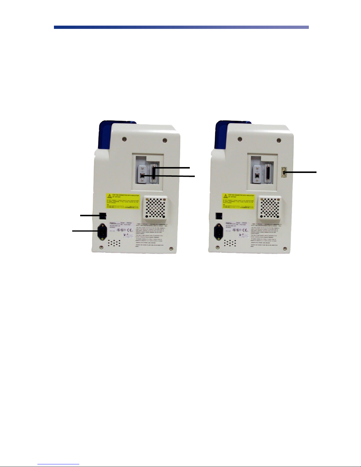
2.1.2 Rear of the Printer
A. Circuit Breaker
Protection device that stops current if there is a direct short or excessive heat.
B. Interface Connection
Available Interface Connection: Refer to Appendix A.
C. Options Connector Port
The printer supports the attachment of an optional card lamination module.
Options connector port not available on PR53LE.
D. Power Receptacle
Supplies power to the printer.
E. RS232C Interface
Interface for RFID encoding and reading modules. Connect using a D-Sub 9 pin
female (DB-9) to a D-Sub 9 pin female. Cable not included. Interface is only
available on models PR5310 and PR5350.
A
B
C
D
E
Figure 2-2: Rear of printer

6
2.1.3 LCD Panel
2.1.4 LCD Operation
ITEM
DESCRIPTION
MODE
FUNCTION
A
LCD Panel
Normal
User
Displays the printer‘s status.
Displays the selected menu or values.
B
Ready LED
Green light indicates printer is ready and
will accept data.
C
Error LED
Indicates an error has occurred.
D
Power LED
Indicates the power is on.
E
Ribbon Change / Menu Button
Normal
User
Press this button to change the ribbon. Press
and hold this button enter User‘s Mode.
Use this button for menu selections.
F
Clear Button
Normal
User
Used for clearing or resetting errors. It is
also used to stop continuous printing.
In some cases, it is used to set values.
G
EXE Button
Normal
User
Not used.
Used to execute the displayed item or to
change the setting.
A
B
C
F
G
D
E
Figure 2-3: Printer LCD panel

7
2.1.5 Front Access Panel
A. Input Roller Module
Removes dust particles from the top and bottom of the card as it feeds into the
printer.
B. Green Retaining Lever
Prevents the ribbon cartridge from being removed.
C. Manual Rotation Knob
Manually advance the rollers.
D. Ribbon Cartridge
Print sharp, colorful images onto various types of cards.
2.2 Unpacking the Printer
Follow these steps to unpack the printer. Be sure to select a location that meets the general
requirements as stated above.
Caution IMPORTANT! The printer must be placed on a level surface, in a dust free
environment. It is essential to be able to access the printer from all sides for its
installation. It is also recommended that you have one or more persons to assist
with unpacking the printer.
1. Place the shipping carton on a firm level surface. While unpacking, inspect the carton to
ensure no damage occurred during shipping.
2. Remove the printer and carton components from the packing box.
3. Open the accessory box and verify the following items are included:
User‘s Guide
Power Supply Cord
Empty Bobbin for Ribbon
A
B
C
D
Figure 2-4: Front access panel

8
Card Weight
Eject Card Box
Ribbon (Refer to Chapter 2.3: Loading The Ribbon)
Ribbon Cartridge
Printer Driver CD
Warranty Registration Card
If any items are missing, please contact your authorized reseller.
Note Keep all packing material in case you need to move or re-ship the printer.
4. Remove all packing tape.
5. Open the front access panel by depressing the release button and lift the green retaining
lever. Gently remove the ribbon cartridge by sliding it toward the front of the printer.
Figure 2-5: Remove tape
Figure 2-6: Front access panel

9
6. Remove the print head packing material from the ribbon cartridge.
2.3 Loading The Ribbon
The PR53xx series printers can accept various ribbon types. Depending on your model, the
following are available ribbon types:
Ribbon Type
PR5300
PR5310
PR5350
PR53LE
K
•
•
•
•
KO
•
•
•
•
YMC
•
•
•
YMCK
•
•
•
YMCK02
•
•
YMCK03(3BP)
•
•
YMCK0K2
•
•
•
Note IMPORTANT! Nisca card printers require special ribbons to function properly.
For this reason, use only genuine Nisca ribbons from Nisca authorized resellers.
Use of non Nisca ribbons may void the warranty and reduce the print quality and
durability.
Figure 2-7: Remove print head packing
10
Caution IMPORTANT! To prevent damage to the print head, you must press the
Ribbon Change button BEFORE removing the ribbon cartridge. Refer to figure
2-3: Printer LCD panel.
Initially, the print head has been retracted at the factory for shipment so you do not have to press
the Ribbon Change button for initial setup. To load the ribbon, follow these steps:
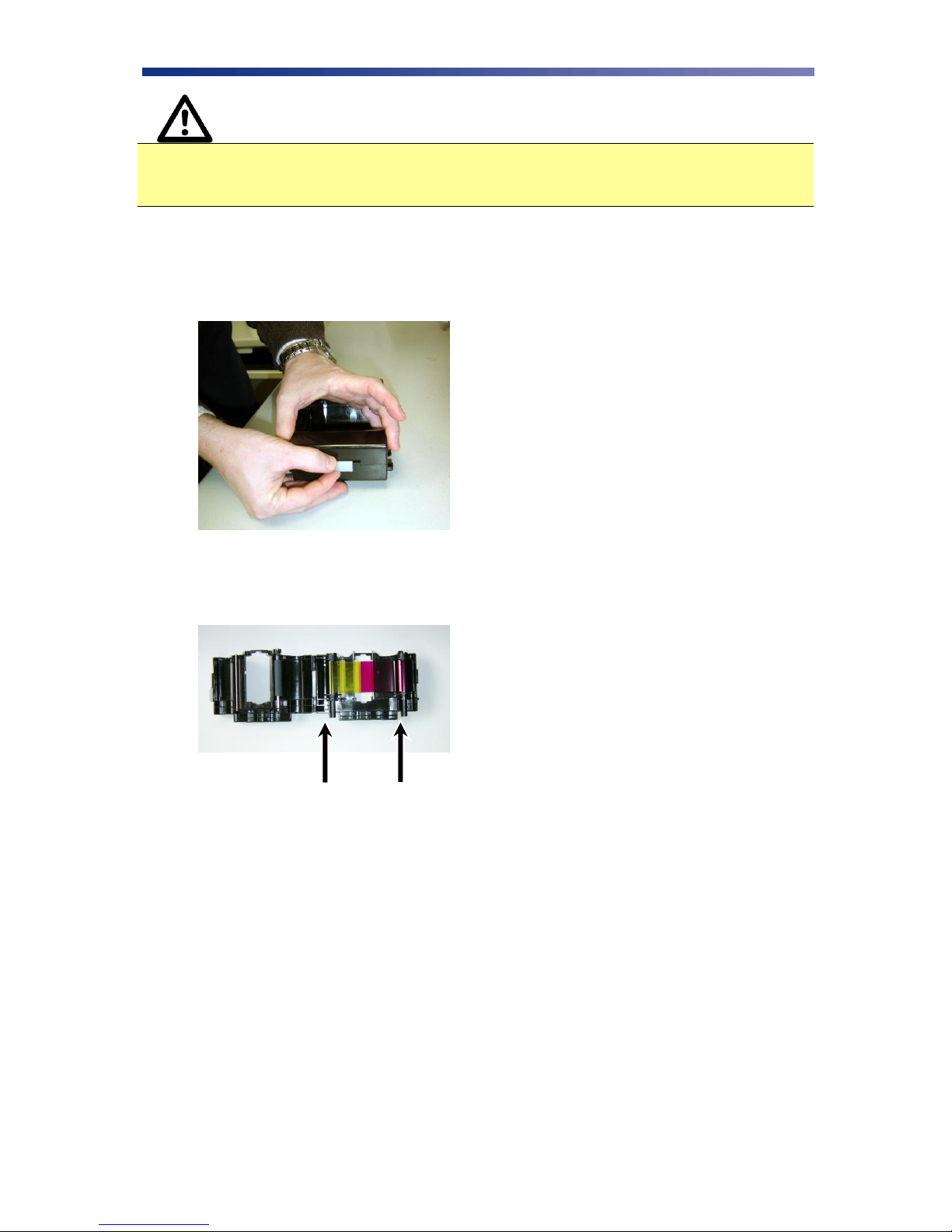
1. Open the ribbon cartridge by sliding the release lever to the left.
2. Remove new ribbon from its packaging and place on the supply side of the ribbon
cartridge.
3. Locate the empty ribbon bobbin packaged with the printer accessories and place on the
take up side of the ribbon cartridge.
Supply Side
Take up Side
Figure 2-8: Open ribbon cartridge
Figure 2-9: Load new ribbon

11
4. Remove the tape and pull the released ribbon towards the take up bobbin. Attach the tape
to the bobbin making sure the ribbon is centered on the bobbin.
5. Advance the takeup bobbin 2-3 turns to verify that the ribbon is properly seated on the
bobbin and all slack has been removed from the ribbon.
6. Close the ribbon cartridge and slide the release lever to the right ensuring the cartridge is
securely locked.
7. Slide the ribbon back into the printer and lower the green retaining lever to lock the
ribbon cartridge in place.
8. Close front access panel.
Note Store ribbons in a cold, dark place. Maximum storage period is 6 months after
delivery if they are kept in an environment of 25º C (77º F), 50% RH. Beyond
this time frame, print quality may be affected.
Figure 2-10: Remove tape
Figure 2-11: Advance bobbin
12
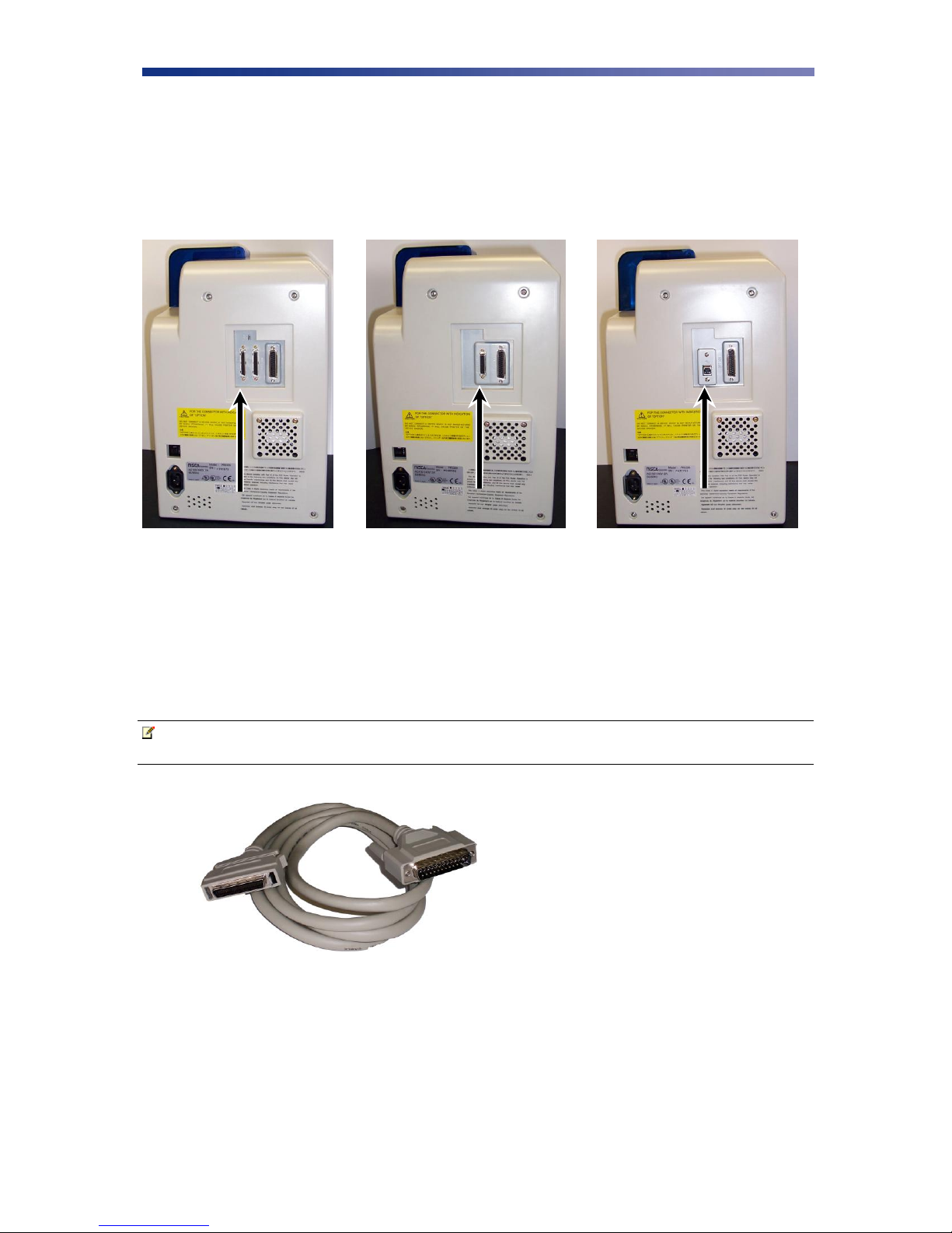
2.4 Connecting The Printer
This section describes how to connect the printer to a power source and to a PC that runs the
printer driver. Depending on the model you purchased, it can be connected either by SCSI,
Parallel, or USB:
To connect the printer to your computer, follow the instructions based on your connectivity.
2.4.1 SCSI Connection
If you are connecting your printer via a SCSI connection, obtain the appropriate interface cable.
Note Use only an external DB25 to 50-pin high density, half pitched Amphenol
connector. TEAMNisca recommends an Adaptec ACK-D2H-1M-ICE.
1. Make sure the computer and printer are turned off.
2. Each SCSI device to be connected in the SCSI chain must be identified with an
individual ID number. There are 7 potential SCSI ID numbers to specify and each SCSI
device must be assigned its own unique ID number. The default SCSI ID number for the
printer is 4.
SCSI
Parallel
USB
Figure 2-12: Printer connection types
Figure 2-13: SCSI cable

13
3. You can set the ID number in the printer by accessing the User Mode Menu. Press and
hold the Menu button on the LCD panel until it displays ―User Mode‖.
4. Press the EXE button several times until the SCSI ID sub menu is displayed. Press the
Menu button to enter this menu and select the appropriate ID number using the EXE
button. The numbers can be between 0-7.
5. Select ―Return to Normal Mode‖ with the MENU button and press the EXE button to
return to the ―Ready to Print‖ display.
6. Depending where your printer exists on the SCSI chain will determine the selection of the
terminating switch. If the printer is in the middle of the chain, the terminating switch
should be in the ―Off‖ position. If the printer is at the end of the chain, then the
terminating switch should be set to ―On‖.
7. Insert the power cord into the power receptacle on the rear of the printer. Plug the other
end into an available wall outlet.
Note The SCSI ID cannot be the same as any other device in your system. SCSI ID 0
is reserved for boot devices and is therefore not recommended for use. The SCSI
interface allows for very high-speed data transmissions. To ensure error free data
transmissions, use the shortest cable possible.
2.4.2 Parallel Connection
To connect the printer to your computer, obtain the appropriate interface cable. A printer to PC
interface cable is a non standard accessory.
Note Use only a shielded, Type C, IEEE 1284 parallel port cable up to a maximum of
6.5 feet long.
1. Make sure the printer and computer are turned off.
Figure 2-14: Parallel cable
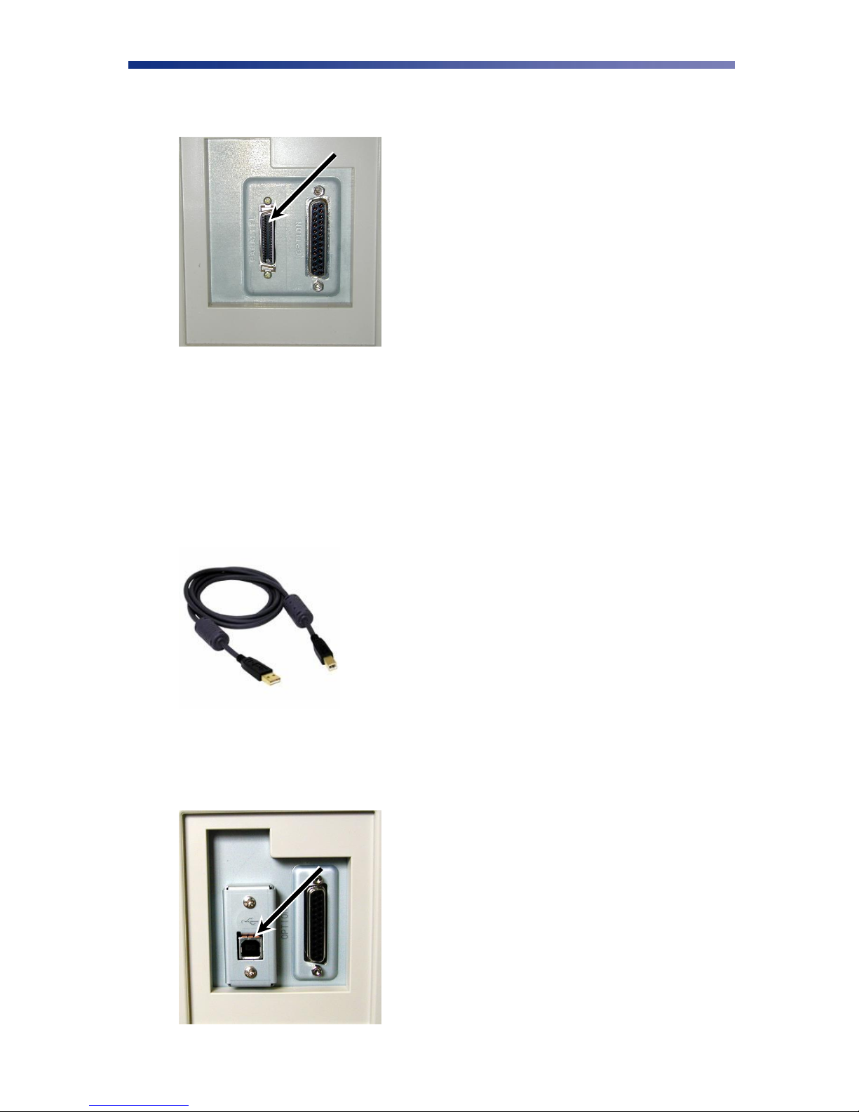
14
2. Connect the micro centronics connector to the printer‘s parallel port, and snap the
fastening clips into place.
3. Connect the other side of the cable to the parallel connector on the back of the computer.
4. Insert the power cord into the power receptacle on the rear of the printer. Plug the other
end into an available wall outlet.
2.4.3 USB Connection
To connect the printer to your computer, obtain the appropriate USB 2.0 cable.
1. Make sure the printer and computer are turned off.
2. Plug the USB 2.0 cable into the printer.
Figure 2-15: Parallel port
Figure 2-16: USB cable
Figure 2-17: USB port

15
3. Plug the other end of the USB cable into the computer.
4. Insert the power cord into the power receptacle on the rear of the printer. Plug the other
end into an available wall outlet.
2.5 Loading Cards
Before you begin printing, you must load blank cards into the printer‘s card feeder. You may
load cards while the printer‘s power is either on or off. You may also load cards while the printer
is printing. The printer is factory configured to feed and print standard size CR-80 card stock at
30 mil. To adjust the card thickness, see Chapter 2.6: Card Thickness Adjustment. To load
cards, follow these steps:
1. Lift the card feeder door and remove the card weight.
2. Remove a new stack of cards from their packaging. Shuffle the cards but be cautious not to
touch the card surface as dirt from your hands could impair the print quality.
3. Holding the stack of cards by their edges, place the cards into the card feeder between the
guides.
4. Always load cards with the primary print side facing up. If inserting cards with a magnetic
stripe, ensure the magnetic stripe is positioned on the bottom and towards the back.
Incorrect positioning will result in encoder write errors.
5. Once the cards are loaded, place the card weight on top of the card stack with the raised
bevel handle facing away from the printer. The card weight increases feeding reliability
primarily when only a few cards are in the card feeder.
6. Close the card feeder door. The cards will automatically feed from the bottom first.
Note Stack the cards evenly to prevent the printer from reporting a ―pick up error‖.
Always store your card stock in its original packing or in a clean, dust-free
container. Ideally, use cards as soon as possible.
Figure 2-18: Stack cards

16
2.6 Card Thickness Adjustment
When loading cards that vary from the standard size, it is necessary to make a simple adjustment
to the printer. To adjust the card size, follow these steps:
1. Open the card feeder door and remove cards.
2. Loosen the two phillips head screws on the adjustable gate.
3. Insert a card into the card feeder just under the gate.
4. Lower the gate until it slightly touches the card.
5. Raise the gate one half the thickness of the card and tighten the screws.
6. Test the new adjustment by attempting to slide two cards under the gate. If two cards
slide under the gate, the gap width is incorrect and return to step 3. You should not be
able to slide two cards into the gap.
Figure 2-19: Adjustable gate
Figure 2-20: Lower gate
Other manuals for Nisca PR5300
1
This manual suits for next models
4
Table of contents
Other Team Nisca Printer manuals


