TEAM WELDER MIG drive Synergic puls User manual

Operating instructions
EN
Wire feed unit
MIG-DRIVE SYNERGIC PULS
299-031000-TWD01
18.10.2016
Observe additional system documents!

General instructions
WARNING
Read the operating instructions!
The operating instructions provide an introduction to the safe use of the products.
•Read and observe the operating instructions for all system components, especially the
safety instructions and warning notices!
•Observe the accident prevention regulations and any regional regulations!
•The operating instructions must be kept at the location where the machine is operated.
•Safety and warning labels on the machine indicate any possible risks.
Keep these labels clean and legible at all times.
•The machine has been constructed to state-of-the-art standards in line with any applicable
regulations and industrial standards. Only trained personnel may operate, service and
repair the machine.
•Technical changes due to further development in machine technology may lead to a
differing welding behaviour.
In the event of queries on installation, commissioning, operation or special conditions at the
installation site, or on usage, please contact your sales partner or our customer service
department on +49 2623 9276400.
A list of authorised sales partners can be found at www.teamwelder.com.
Liability relating to the operation of this equipment is restricted solely to the function of the
equipment. No other form of liability, regardless of type, shall be accepted. This exclusion of
liability shall be deemed accepted by the user on commissioning the equipment.
The manufacturer is unable to monitor whether or not these instructions or the conditions and
methods are observed during installation, operation, usage and maintenance of the equipment.
An incorrectly performed installation can result in material damage and injure persons as a
result. For this reason, we do not accept any responsibility or liability for losses, damages or
costs arising from incorrect installation, improper operation or incorrect usage and maintenance
or any actions connected to this in any way.
TEAMWELDER Germany GmbH
Sälzerstraße 20a
D-56235 Ransbach-Baumbach
Deutschland / Germany
The copyright to this document remains the property of the manufacturer.
Reprinting, including extracts, only permitted with written approval.
The content of this document has been prepared and reviewed with all reasonable care. The information
provided is subject to change; errors excepted.

Contents
Notes on the use of these operating instructions
299-031000-TWD01
18.10.2016
3
1 Contents
1Contents..................................................................................................................................................3
2For your safety .......................................................................................................................................6
2.1 Notes on the use of these operating instructions ..........................................................................6
2.2 Explanation of icons.......................................................................................................................7
2.3 Part of the complete documentation..............................................................................................8
2.4 Safety instructions..........................................................................................................................9
2.5 Transport and installation ............................................................................................................13
3Intended use.........................................................................................................................................14
3.1 Applications..................................................................................................................................14
3.2 Use and operation solely with the following machines ................................................................14
3.3 Documents which also apply .......................................................................................................15
3.3.1 Warranty.......................................................................................................................15
3.3.2 Declaration of Conformity.............................................................................................15
3.3.3 Service documents (spare parts and circuit diagrams)................................................15
3.3.4 Calibration/Validation....................................................................................................15
4Machine description –quick overview ..............................................................................................16
4.1 Front view ....................................................................................................................................16
4.2 Rear view.....................................................................................................................................17
4.3 Inside view ...................................................................................................................................18
4.4 Machine control –Operating elements........................................................................................19
5Design and function.............................................................................................................................21
5.1 Transport and installation ............................................................................................................21
5.1.1 Ambient conditions .......................................................................................................21
5.1.1.1 In operation ...................................................................................................21
5.1.1.2 Transport and storage...................................................................................21
5.1.2 Notes on the installation of welding current leads........................................................22
5.1.2.1 Stray welding currents...................................................................................23
5.1.3 Intermediate hose package connection........................................................................24
5.1.4 Intermediate hose package strain relief .......................................................................25
5.1.5 Shielding gas supply (shielding gas cylinder for welding machine) .............................26
5.1.5.1 Pressure regulator connection......................................................................26
5.1.5.2 Shielding gas volume settings ......................................................................27
5.1.5.3 Gas test.........................................................................................................27
5.1.5.4 Purge hose package.....................................................................................27
5.1.6 Welding torch cooling system.......................................................................................28
5.1.6.1 Approved coolants overview.........................................................................28
5.1.6.2 Maximal hose package length ......................................................................28
5.2 Welding data display....................................................................................................................29
5.2.1 Polarity setting..............................................................................................................29
5.3 MIG/MAG welding........................................................................................................................30
5.3.1 Welding torch connection.............................................................................................30
5.3.2 Wire feed......................................................................................................................32
5.3.2.1 Open the protective flap of the wire feeder...................................................32
5.3.2.2 Inserting the wire spool.................................................................................33
5.3.2.3 Changing the wire feed rollers ......................................................................34
5.3.2.4 Inching the wire electrode.............................................................................34
5.3.2.5 Spool brake setting .......................................................................................36
5.3.3 Definition of MIG/MAG welding tasks...........................................................................37
5.3.4 Welding task selection..................................................................................................38
5.3.4.1 Choke effect / dynamics................................................................................39
5.3.5 MIG/MAG operating point.............................................................................................40
5.3.5.1 Selecting the welding parameter display mode ............................................40
5.3.5.2 Operating point setting using material thickness ..........................................40
5.3.5.3 Arc length correction setting .........................................................................40

Contents
Notes on the use of these operating instructions
4
299-031000-TWD01
18.10.2016
5.3.6 Further welding parameters..........................................................................................41
5.3.7 MIG/MAG functional sequences / operating modes.....................................................42
5.3.7.1 Explanation of signs and functions................................................................42
5.3.8 Conventional MIG/MAG Welding (GMAW non synergic).............................................45
5.3.8.1 Setting the operating point (welding output)..................................................46
5.3.9 MIG/MAG automatic cut-out.........................................................................................46
5.4 TIG welding..................................................................................................................................47
5.4.1 Welding torch connection .............................................................................................47
5.4.2 Welding task selection..................................................................................................48
5.4.2.1 Welding current setting..................................................................................48
5.4.3 Further welding parameters..........................................................................................49
5.4.4 TIG arc ignition .............................................................................................................50
5.4.4.1 Liftarc.............................................................................................................50
5.4.5 Function sequences/operating modes..........................................................................51
5.4.5.1 Legend...........................................................................................................51
5.4.6 TIG automatic cut-out...................................................................................................53
5.5 MMA welding................................................................................................................................54
5.5.1 Welding task selection..................................................................................................54
5.5.1.1 Welding current setting..................................................................................55
5.5.2 Arcforce.........................................................................................................................55
5.5.3 Hotstart .........................................................................................................................55
5.5.3.1 Hotstart settings ............................................................................................56
5.5.4 Antistick.........................................................................................................................56
5.6 Remote control.............................................................................................................................57
5.7 Special parameters (advanced settings)......................................................................................58
5.7.1 Selecting, changing and saving parameters.................................................................59
5.7.1.1 Reset to factory settings................................................................................60
5.7.1.2 Special parameters in detail..........................................................................61
5.8 Machine configuration menu........................................................................................................62
5.8.1 Selecting, changing and saving parameters.................................................................62
5.8.2 Power-saving mode (Standby) .....................................................................................62
6Maintenance, care and disposal .........................................................................................................63
6.1 General.........................................................................................................................................63
6.2 Cleaning.......................................................................................................................................63
6.3 Maintenance work, intervals.........................................................................................................64
6.3.1 Daily maintenance tasks...............................................................................................64
6.3.1.1 Visual inspection ...........................................................................................64
6.3.1.2 Functional test...............................................................................................64
6.3.2Monthly maintenance tasks..........................................................................................64
6.3.2.1 Visual inspection ...........................................................................................64
6.3.2.2 Functional test...............................................................................................64
6.3.3Annual test (inspection and testing during operation) ..................................................65
6.4 Disposing of equipment................................................................................................................65
6.4.1 Manufacturer's declaration to the end user ..................................................................65
6.5 Meeting the requirements of RoHS..............................................................................................65
7Rectifying faults....................................................................................................................................66
7.1 Checklist for rectifying faults ........................................................................................................66
7.2 Error messages............................................................................................................................67
7.3 Resetting JOBs (welding tasks) to the factory settings................................................................69
7.3.1 Resetting a single JOB.................................................................................................69
7.3.2 Resetting all JOBs ........................................................................................................69
7.4 Display machine control software version....................................................................................69
7.5 Vent coolant circuit.......................................................................................................................70
8Technical data.......................................................................................................................................71
8.1 MIG-DRIVE SYNERGIC PULS....................................................................................................71
9Accessories ..........................................................................................................................................72
9.1 Internet.........................................................................................................................................72

Contents
Notes on the use of these operating instructions
299-031000-TWD01
18.10.2016
5
10 Replaceable parts ................................................................................................................................73
10.1 Wire feed rollers...........................................................................................................................73
10.1.1 Wire feed rollers for steel wire......................................................................................73
10.1.2 Wire feed rollers for aluminium wire.............................................................................73
10.1.3 Wire feed rollers for cored wire ....................................................................................73
10.1.4 Conversion kit...............................................................................................................74
11 Appendix A ...........................................................................................................................................75
11.1 JOB-List .......................................................................................................................................75
12 Appendix B ...........................................................................................................................................76
12.1 Parameter overview –setting information ...................................................................................76

For your safety
Notes on the use of these operating instructions
6
299-031000-TWD01
18.10.2016
2 For your safety
2.1 Notes on the use of these operating instructions
DANGER
Working or operating procedures which must be closely observed to prevent imminent
serious and even fatal injuries.
•Safety notes include the "DANGER" keyword in the heading with a general warning symbol.
•The hazard is also highlighted using a symbol on the edge of the page.
WARNING
Working or operating procedures which must be closely observed to prevent serious
and even fatal injuries.
•Safety notes include the "WARNING" keyword in the heading with a general warning
symbol.
•The hazard is also highlighted using a symbol in the page margin.
CAUTION
Working or operating procedures which must be closely observed to prevent possible
minor personal injury.
•The safety information includes the "CAUTION" keyword in its heading with a general
warning symbol.
•The risk is explained using a symbol on the edge of the page.
Special technical points which users must observe.
Instructions and lists detailing step-by-step actions for given situations can be recognised via bullet
points, e.g.:
•Insert the welding current lead socket into the relevant socket and lock.
For your safety
Explanation of icons
299-031000-TWD01
18.10.2016
7
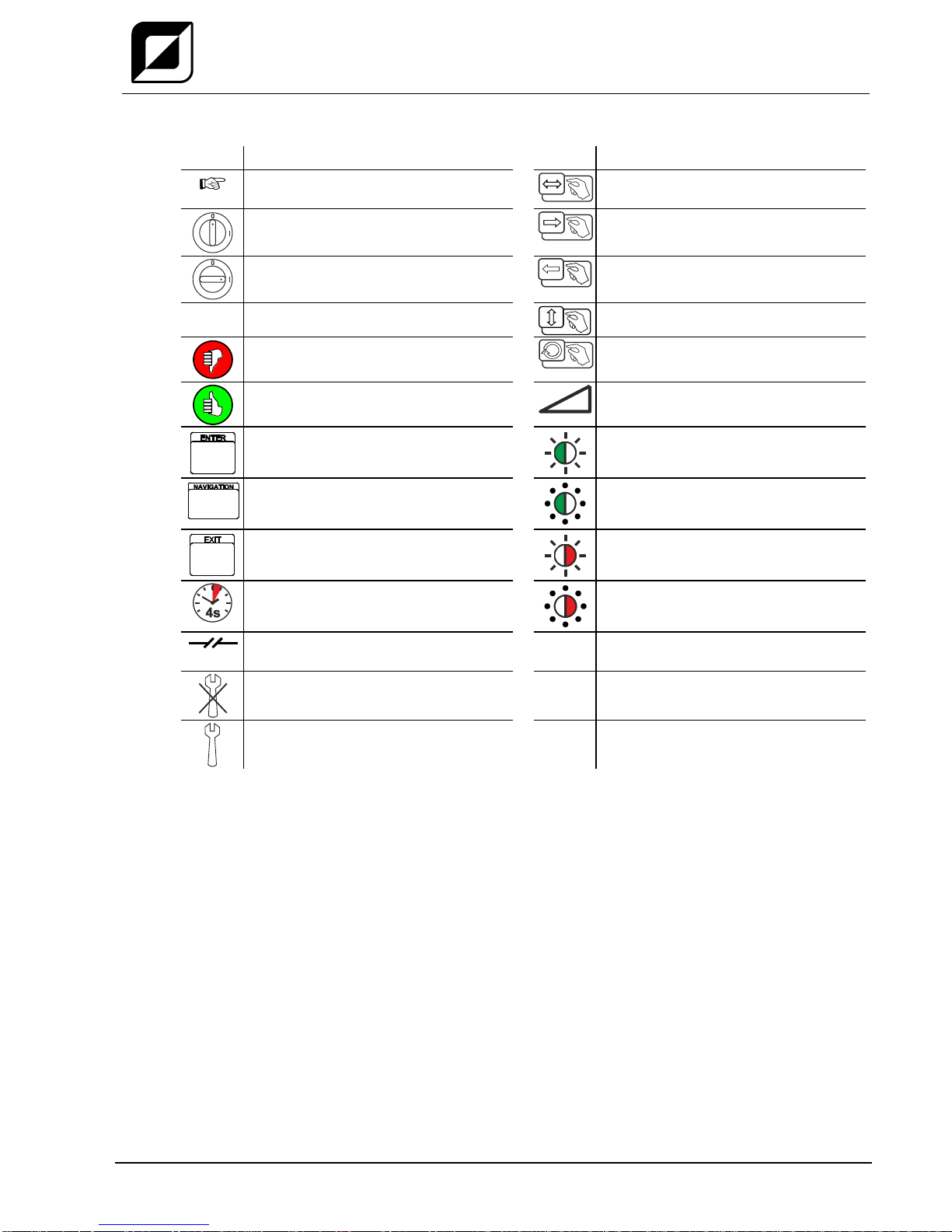
2.2 Explanation of icons
Symbol
Description
Symbol
Description
Indicates technical aspects which the
user must observe.
Activate and release/tap/tip
Switch off machine
Release
Switch on machine
Press and keep pressed
Switch
Wrong
Turn
Correct
Numerical value –adjustable
Menu entry
Signal light lights up in green
Navigating the menu
Signal light flashes green
Exit menu
Signal light lights up in red
Time representation (e.g.: wait
4 s/activate)
Signal light flashes red
Interruption in the menu display (other
setting options possible)
Tool not required/do not use
Tool required/use
For your safety
Part of the complete documentation
8
299-031000-TWD01
18.10.2016
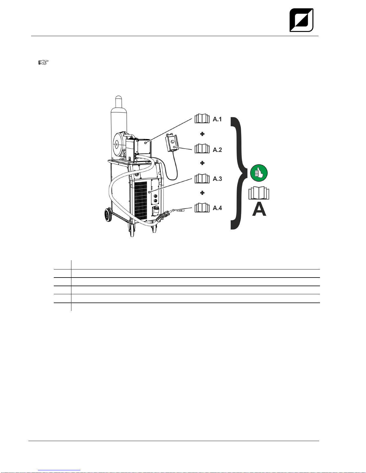
2.3 Part of the complete documentation
These operating instructions are part of the complete documentation and valid only in
combination with all other parts of these instructions! Read and observe the operating
instructions for all system components, especially the safety instructions!
The illustration shows a general example of a welding system.
Figure 2-1
The illustration shows a general example of a welding system.
Item
Documentation
A.1
Wire feeder
A.2
Remote control
A.3
Power source
A.4
Welding torch
A
Complete documentation
For your safety
Safety instructions
299-031000-TWD01
18.10.2016
9
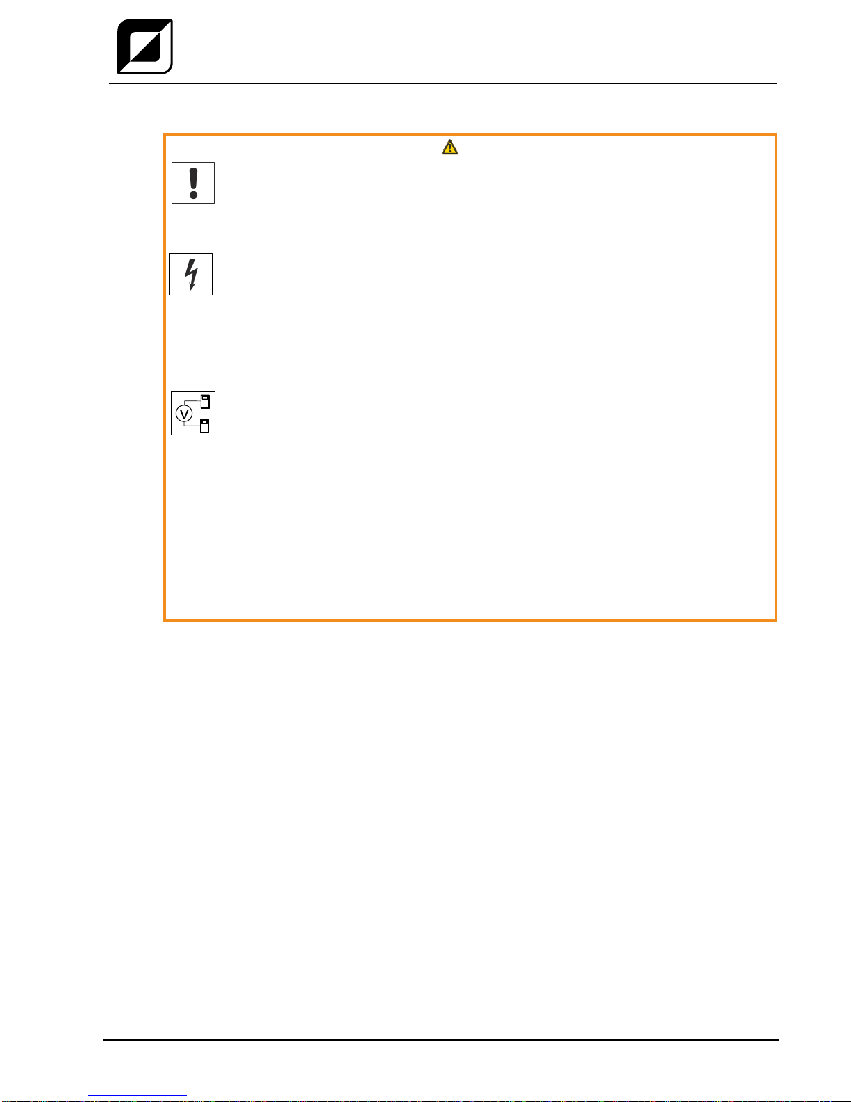
2.4 Safety instructions
WARNING
Risk of accidents due to non-compliance with the safety instructions!
Non-compliance with the safety instructions can be fatal!
•Carefully read the safety instructions in this manual!
•Observe the accident prevention regulations and any regional regulations!
•Inform persons in the working area that they must comply with the regulations!
Risk of injury from electrical voltage!
Voltages can cause potentially fatal electric shocks and burns on contact. Even low
voltages can cause a shock and lead to accidents.
•Never touch live components such as welding current sockets or stick, tungsten or wire
electrodes!
•Always place torches and electrode holders on an insulated surface!
•Wear the full personal protective equipment (depending on the application)!
•The machine may only be opened by qualified personnel!
Hazard when interconnecting multiple power sources!
If a number of power sources are to be connected in parallel or in series, only a
technical specialist may interconnect the sources as per standard IEC 60974-9:2010:
Installation and use and German Accident Prevention Regulation BVG D1 (formerly VBG
15) or country-specific regulations.
Before commencing arc welding, a test must verify that the equipment cannot exceed
the maximum permitted open circuit voltage.
•Only qualified personnel may connect the machine.
•When taking individual power sources out of operation, all mains and welding current leads
must be safely disconnected from the welding system as a whole. (Hazard due to reverse
polarity voltage!)
•Do not interconnect welding machines with pole reversing switch (PWS series) or machines
for AC welding since a minor error in operation can cause the welding voltages to be
combined, which is not permitted.
For your safety
Safety instructions
10
299-031000-TWD01
18.10.2016
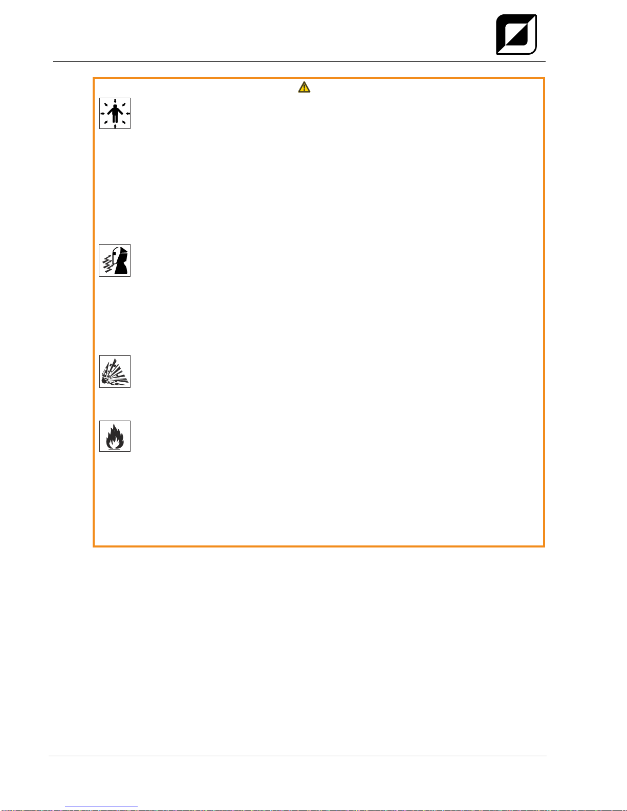
WARNING
Risk of injury due to improper clothing!
During arc welding, radiation, heat and voltage are sources of risk that cannot be
avoided. The user has to be equipped with the complete personal protective equipment
at all times. The protective equipment has to include:
•Respiratory protection against hazardous substances and mixtures (fumes and vapours);
otherwise implement suitable measures such as extraction facilities.
•Welding helmet with proper protection against ionizing radiation (IR and UV radiation) and
heat.
•Dry welding clothing (shoes, gloves and body protection) to protect against warm
environments with conditions comparable to ambient temperatures of 100 °C or higher and
arcing and work on live components.
•Hearing protection against harming noise.
Risk of injury due to radiation or heat!
Arc radiation results in injury to skin and eyes.
Contact with hot workpieces and sparks results in burns.
•Use welding shield or welding helmet with the appropriate safety level (depending on the
application)!
•Wear dry protective clothing (e.g. welding shield, gloves, etc.) according to the relevant
regulations in the country in question!
•Protect persons not involved in the work against arc beams and the risk of glare using
safety curtains!
Explosion risk!
Apparently harmless substances in closed containers may generate excessive pressure
when heated.
•Move containers with inflammable or explosive liquids away from the working area!
•Never heat explosive liquids, dusts or gases by welding or cutting!
Fire hazard!
Due to the high temperatures, sparks, glowing parts and hot slag that occur during
welding, there is a risk of flames.
•Be watchful of potential sources of fire in the working area!
•Do not carry any easily inflammable objects, e.g. matches or lighters.
•Ensure suitable fire extinguishers are available in the working area!
•Thoroughly remove any residue of flammable materials from the workpiece prior to starting
to weld.
•Only further process workpieces after they have cooled down. Do not allow them to contact
any flammable materials!
For your safety
Safety instructions
299-031000-TWD01
18.10.2016
11
CAUTION
Smoke and gases!
Smoke and gases can lead to breathing difficulties and poisoning. In addition, solvent
vapour (chlorinated hydrocarbon) may be converted into poisonous phosgene due to
the ultraviolet radiation of the arc!
•Ensure that there is sufficient fresh air!
•Keep solvent vapour away from the arc beam field!
•Wear suitable breathing apparatus if appropriate!
Noise exposure!
Noise exceeding 70 dBA can cause permanent hearing damage!
•Wear suitable ear protection!
•Persons located within the working area must wear suitable ear protection!
Obligations of the operator!
The respective national directives and laws must be complied with when operating the machine!
•Implementation of national legislation relating to framework directive 89/391/EEC on the
introduction of measures to encourage improvements in the safety and health of workers at
work and associated individual guidelines.
•In particular, directive 89/655/EEC concerning the minimum safety and health requirements for
the use of work equipment by workers at work.
•The regulations applicable to occupational safety and accident prevention in the country
concerned.
•Setting up and operating the machine as per IEC 60974.-9.
•Brief the user on safety-conscious work practices on a regular basis.
•Regularly inspect the machine as per IEC 60974.-4.
The manufacturer's warranty becomes void if non-genuine parts are used!
•Only use system components and options (power sources, welding torches, electrode
holders, remote controls, spare parts and replacement parts, etc.) from our range of products!
•Only insert and lock accessory components into the relevant connection socket when the
machine is switched off.
Requirements for connection to the public mains network
High-performance machines can influence the mains quality by taking current from the mains
network. For some types of machines, connection restrictions or requirements relating to the
maximum possible line impedance or the necessary minimum supply capacity at the interface
with the public network (Point of Common Coupling, PCC) can therefore apply. In this respect,
attention is also drawn to the machines' technical data. In this case, it is the responsibility of the
operator, where necessary in consultation with the mains network operator, to ensure that the
machine can be connected.
For your safety
Safety instructions
12
299-031000-TWD01
18.10.2016
CAUTION
Electromagnetic fields!
The power source may cause electrical or electromagnetic fields to be produced which
could affect the correct functioning of electronic equipment such as IT or CNC devices,
telecommunication lines, power cables, signal lines and pacemakers.
•Observe the maintenance instructions > see 6.3 chapter!
•Unwind welding leads completely!
•Shield devices or equipment sensitive to radiation accordingly!
•The correct functioning of pacemakers may be affected (obtain advice from a doctor if
necessary).
According to IEC 60974-10, welding machines are divided into two classes of
electromagnetic compatibility (the EMC class can be found in the Technical
data) > see 8 chapter:
Class A machines are not intended for use in residential areas where the power supply comes
from the low-voltage public mains network. When ensuring the electromagnetic compatibility of
class A machines, difficulties can arise in these areas due to interference not only in the supply
lines but also in the form of radiated interference.
Class B machines fulfil the EMC requirements in industrial as well as residential areas,
including residential areas connected to the low-voltage public mains network.
Setting up and operating
When operating arc welding systems, in some cases, electro-magnetic interference can occur
although all of the welding machines comply with the emission limits specified in the standard.
The user is responsible for any interference caused by welding.
In order to evaluate any possible problems with electromagnetic compatibility in the
surrounding area, the user must consider the following: (see also EN 60974-10 Appendix A)
•Mains, control, signal and telecommunication lines
•Radios and televisions
•Computers and other control systems
•Safety equipment
•The health of neighbouring persons, especially if they have a pacemaker or wear a hearing
aid
•Calibration and measuring equipment
•The immunity to interference of other equipment in the surrounding area
•The time of day at which the welding work must be carried out
Recommendations for reducing interference emission
•Mains connection, e.g. additional mains filter or shielding with a metal tube
•Maintenance of the arc welding system
•Welding leads should be as short as possible and run closely together along the ground
•Potential equalization
•Earthing of the workpiece. In cases where it is not possible to earth the workpiece directly,
it should be connected by means of suitable capacitors.
•Shielding from other equipment in the surrounding area or the entire welding system
For your safety
Transport and installation
299-031000-TWD01
18.10.2016
13
2.5 Transport and installation
WARNING
Risk of injury due to improper handling of shielding gas cylinders!
Improper handling and insufficient securing of shielding gas cylinders can cause
serious injuries!
•Observe the instructions from the gas manufacturer and any relevant regulations
concerning the use of compressed air!
•Do not attach any element to the shielding gas cylinder valve!
•Prevent the shielding gas cylinder from heating up.
CAUTION
Risk of accidents due to supply lines!
During transport, attached supply lines (mains leads, control cables, etc.) can cause
risks, e.g. by causing connected machines to tip over and injure persons!
•Disconnect all supply lines before transport!
Risk of tipping!
There is a risk of the machine tipping over and injuring persons or being damaged itself
during movement and set up. Tilt resistance is guaranteed up to an angle of 10°
(according to IEC 60974-1).
•Set up and transport the machine on level, solid ground.
•Secure add-on parts using suitable equipment.
The units are designed for operation in an upright position!
Operation in non-permissible positions can cause equipment damage.
•Only transport and operate in an upright position!
Accessory components and the power source itself can be damaged by incorrect connection!
•Only insert and lock accessory components into the relevant connection socket when the
machine is switched off.
•Comprehensive descriptions can be found in the operating instructions for the relevant
accessory components.
•Accessory components are detected automatically after the power source is switched on.
Protective dust caps protect the connection sockets and therefore the machine against dirt and
damage.
•The protective dust cap must be fitted if there is no accessory component being operated on
that connection.
•The cap must be replaced if faulty or if lost!

Intended use
Applications
14
299-031000-TWD01
18.10.2016
3 Intended use
WARNING
Hazards due to improper usage!
The machine has been constructed to the state of the art and any regulations and
standards applicable for use in industry and trade. It may only be used for the welding
procedures indicated at the rating plate. Hazards may arise for persons, animals and
material objects if the equipment is not used correctly. No liability is accepted for any
damages arising from improper usage!
•The equipment must only be used in line with its designated purpose and by trained or
expert personnel!
•Do not improperly modify or convert the equipment!
3.1 Applications
Wire feeder to feed wire electrodes for gas-shielded metal-arc welding.
3.2 Use and operation solely with the following machines
A suitable power source (system component) is required in order to operate the wire feed unit!
•MIG 400 SYNERGIC DG
•MIG 400 SYNERGIC DW
•MIG 400 SYNERGIC PULS DG
•MIG 400 SYNERGIC PULS DW
Intended use
Documents which also apply
299-031000-TWD01
18.10.2016
15
3.3 Documents which also apply
3.3.1 Warranty
For more information on the warranty topic refer to the included CD-ROM or the website:
www.teamwelder.com.
3.3.2 Declaration of Conformity
The labelled machine complies with EC directives in terms of its design and
construction:
•EC Low Voltage Directive (2006/95/EC)
•EC EMC Directive (2004/108/EC)
In case of unauthorised changes, improper repairs, non-compliance with specified deadlines for "Arc
Welding Equipment –Inspection and Testing during Operation", and/or prohibited modifications which
have not been explicitly authorised by TEAMWELDER, this declaration shall be voided. An original
document of the specific declaration of conformity is included with every product.
3.3.3 Service documents (spare parts and circuit diagrams)
WARNING
Do not carry out any unauthorised repairs or modifications!
To avoid injury and equipment damage, the unit must only be repaired or modified by
specialist, skilled persons!
The warranty becomes null and void in the event of unauthorised interference.
•Appoint only skilled persons for repair work (trained service personnel)!
Original copies of the circuit diagrams are enclosed with the unit.
To obtain spare parts, please refer to the included CD-ROM or contact your local authorised dealer.
3.3.4 Calibration/Validation
We hereby confirm that this machine has been tested using calibrated measuring equipment, as
stipulated in IEC/EN 60974, ISO/EN 17662, EN 50504, and complies with the admissible tolerances.
Recommended calibration interval: 12 months
Machine description –quick overview
Front view
16
299-031000-TWD01
18.10.2016
4 Machine description – quick overview
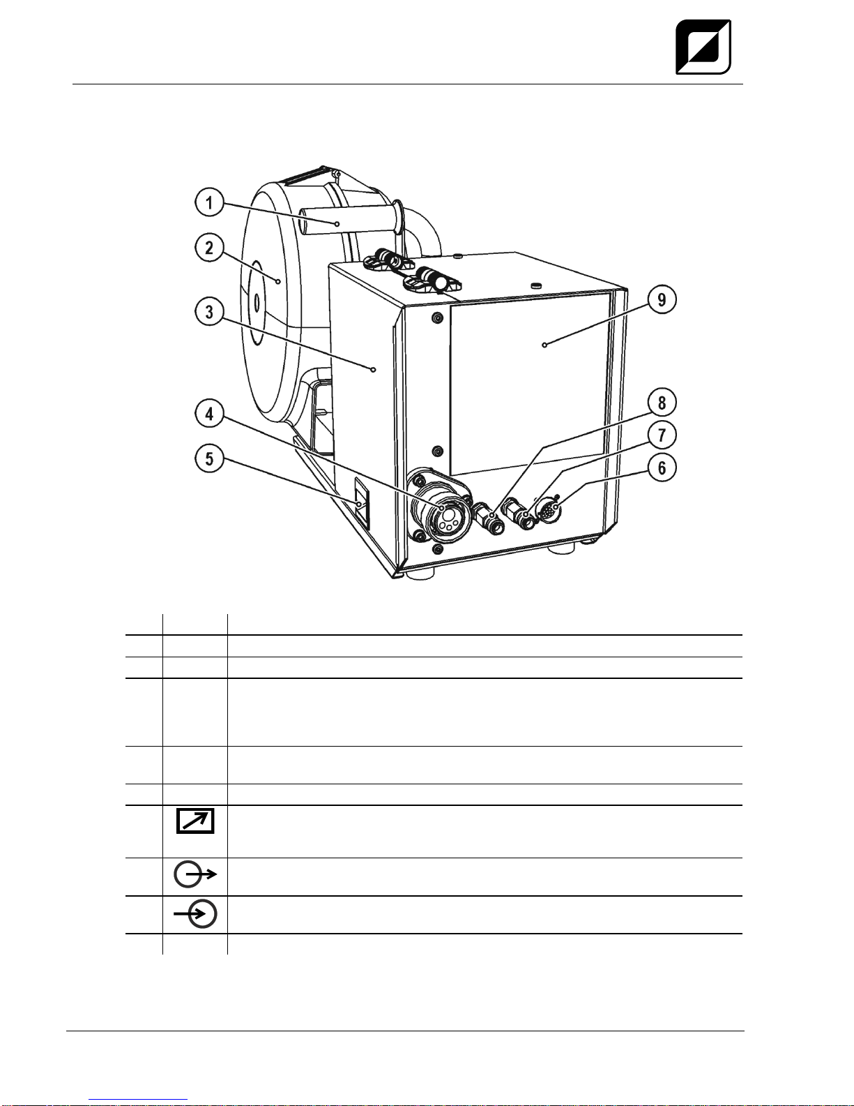
4.1 Front view
Figure 4-1
Item
Symbol
Description 0
1
Carrying handle
2
Wire spool casing
3
Protective cap
Cover for the wire feed mechanism and other operating elements.
Depending on the machine series, additional stickers with information on the
replacement parts and JOB lists will be located on the inside.
4
Welding torch connection (Euro or Dinse torch connector)
Welding current, shielding gas and torch trigger integrated
5
Slide latch, lock for the protective cap
6
19-pole connection socket (analogue)
For connecting analogue accessory components (remote control, welding torch control
lead, etc.)
7
Quick connect coupling (blue)
coolant supply
8
Quick connect coupling (red)
coolant return
9
Machine control > see 4.4 chapter
Machine description –quick overview
Rear view
299-031000-TWD01
18.10.2016
17
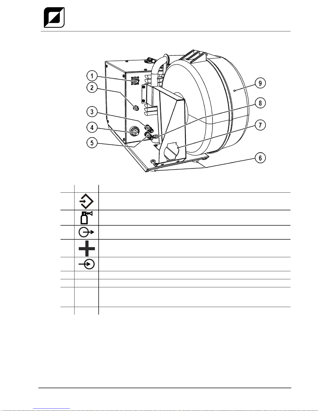
4.2 Rear view
Figure 4-2
Item
Symbol
Description 0
1
7-pole connection socket (digital)
•Control lead for wire feed unit
2
Connecting nipple G¼, shielding gas connection
3
Quick connect coupling (red)
coolant return
4
Connector plug, welding current "+"
Welding current connection on wire feed unit
5
Quick connect coupling (blue)
coolant supply
6
Machine feet
7
Intermediate hose package strain relief > see 5.1.4 chapter
8
Turning mandrel support
The wire feeder is placed onto the power source turning mandrel using this support to
enable horizontal pivoting of the machine.
9
Wire spool casing
Machine description –quick overview
Inside view
18
299-031000-TWD01
18.10.2016
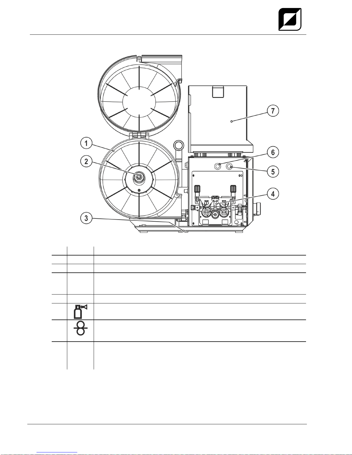
4.3 Inside view
Figure 4-3
Item
Symbol
Description 0
1
Wire spool casing
2
Wire spool holder
3
Turning mandrel support
The wire feeder is placed onto the power source turning mandrel using this support to
enable horizontal pivoting of the machine.
4
Wire feed unit
5
Push-button gas test / rinse hose package > see 5.1.5.3 chapter
6
Wire inching push-button
For potential- and gas-free inching of the wire electrode through the hose package to
the welding torch.
7
Protective cap
Cover for the wire feed mechanism and other operating elements.
Depending on the machine series, additional stickers with information on the
replacement parts and JOB lists will be located on the inside.
Machine description –quick overview
Machine control –Operating elements
299-031000-TWD01
18.10.2016
19
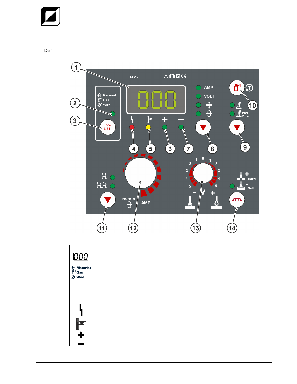
4.4 Machine control –Operating elements
The setting ranges for the parameter values are summarised in the Parameter overview
section > see 12.1 chapter.
Figure 4-4
Item
Symbol
Description 0
1
Welding data display (3-digit)
Displays the welding parameters and the corresponding values > see 5.2 chapter
2
Signal light, JOB-List
Illuminates upon display or selection of the JOB number
3
JOB-
LIST
Welding task push-button (JOB)
Select the welding task from the welding task list (JOB-LIST). The list can be found
inside the protective cap on the wire feeder and in the appendix to these operating
instructions.
4
“Collective interference” signal light
5
“Excess temperature” signal light
6
Signal light polarity setting
7
Signal light polarity setting
Machine description –quick overview
Machine control –Operating elements
20
299-031000-TWD01
18.10.2016
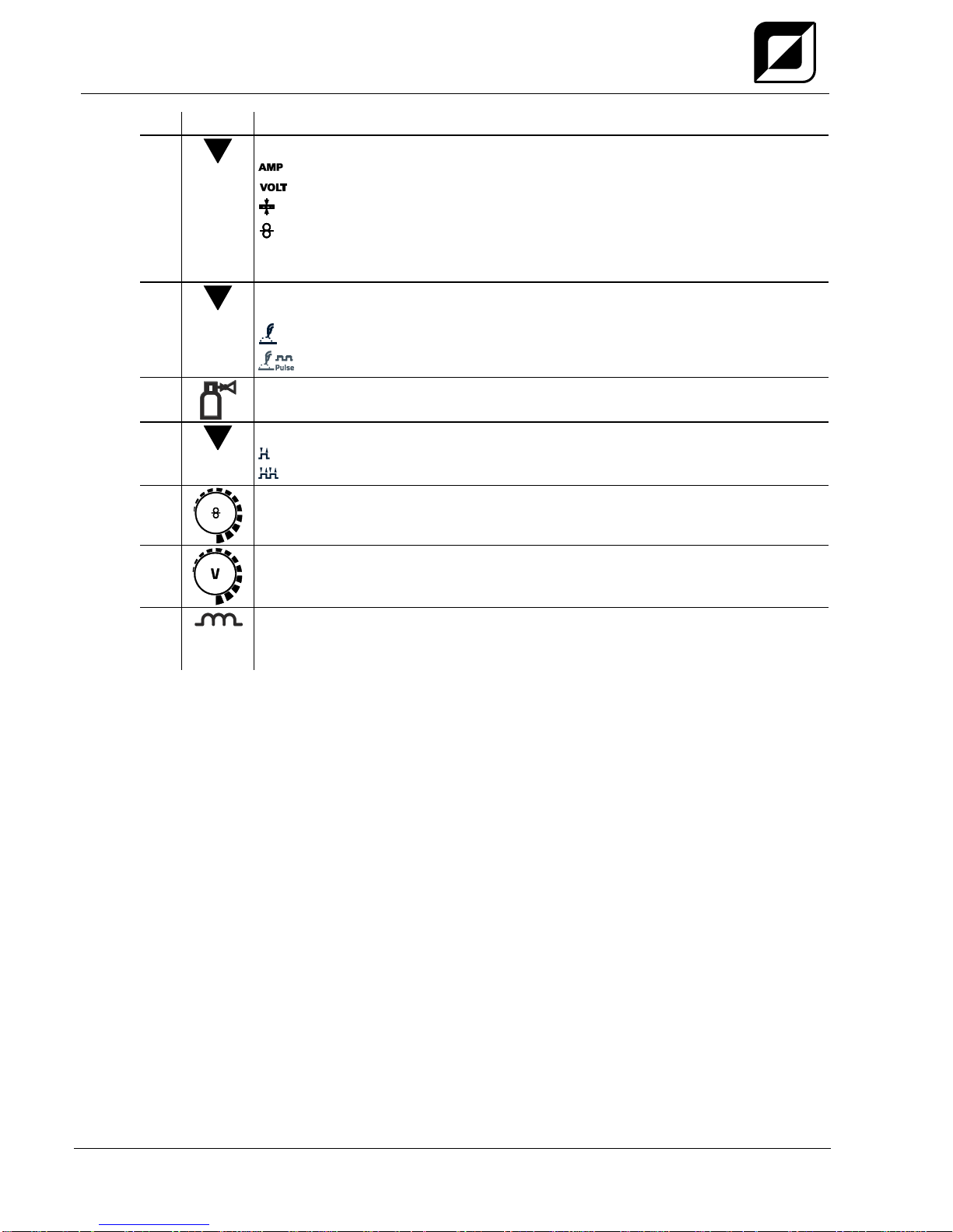
Item
Symbol
Description 0
8
Welding parameter display mode/power-saving mode push-button
------ Welding current
----- Welding voltage
-------- Material thickness
-------- Wire feed speed
Press for 2 s to put the machine into power-saving mode.
To reactivate, activate one of the operating elements > see 5.8.2 chapter.
9
"Welding type" push-button (for machine versions with pulsed arc welding
procedures only)
------- standard MIG/MAG welding
---- pulsed MIG/MAG welding
10
Push-button gas test / rinse hose package > see 5.1.5.3 chapter
11
Select operating mode button
--------- Non-latched
------- Latched
12
Welding parameter setting dial
For setting the welding performance, for selecting the JOB (welding task) and for
setting other welding parameters.
13
Arc length correction rotary dial
14
Choke effect/Arcforce push-button
MIG/MAG Choke effect (arc dynamics) > see 5.3.4 chapter
MMA ---- Arcforce > see 5.5.1 chapter
Table of contents
Other TEAM WELDER Welding System manuals

TEAM WELDER
TEAM WELDER MMA 160 User manual

TEAM WELDER
TEAM WELDER MIG 302 S SYNERGIC User manual

TEAM WELDER
TEAM WELDER TIG 180 DC User manual

TEAM WELDER
TEAM WELDER TIG 180 AC/DC puls User manual

TEAM WELDER
TEAM WELDER Plasma CUT 65 User manual

TEAM WELDER
TEAM WELDER MIG 250 S User manual

TEAM WELDER
TEAM WELDER TIG 180 AC/DC User manual
Popular Welding System manuals by other brands

WARPP
WARPP INTIG 401 Operator's manual

ESAB
ESAB A6 TFD1 Simplified service manual

HERKULES
HERKULES ES 150 Turbo instruction manual

SPT Plasmateknik AB
SPT Plasmateknik AB UNIFIRE 31PFC Instructions for use

Hobart Welding Products
Hobart Welding Products LX 160 DC Specification sheet

Thermal Dynamics
Thermal Dynamics C-20A Cutskill Service manual


