Shop Iron 41199 User manual

30 Amp Plasma Cutter
# 41199
Please read and understand this instruction manual carefully before the installation and
operation of this equipment.
BUILT TO GET THE JOB DONE
ONE YEAR LIMITED WARRANTY
Star Asia-USA, LLC (hereinafter “seller”) warrants to the original purchaser only, that this product will be free from defects in
material or workmanship for a period of one year from date of purchase.
Warranty Performance
Warranty coverage is conditioned upon purchaser furnishing seller or its authorized service center with adequate written
proof of the original purchase date. Products returned, freight prepaid and insured, to our factory or to an Authorized Service
Center will be inspected and repaired or replaced, at seller’s option, free of charge if found to be defective and subject to
warranty. Defective parts not subject to normal wear and tear will be repaired or replaced, at our option during the above
stated warranty periods. In any event, reimbursement is limited to the purchase price paid. Other than the postage and
insurance requirement, no charge will be made for repairs or replacements covered by this warranty. Under no circumstances
shall the manufacturer bear any responsibility for loss of the unit, loss of time or rental, inconvenience, commercial loss or
consequential damages. There are no warranties which extend beyond the description of the face hereof.
Exclusions
This warranty does not cover parts damaged due to normal wear, abnormal conditions, misapplication, misuse, abuse,
accidents, operation at other than recommended pressures or temperatures, improper storage or freight damage. Parts
damaged or worn by operation in dusty environments are not warranted. Failure to follow recommended operating and
maintenance procedures also voids warranty.
Additional items not covered under this warranty: product failure caused by rain, excessive humidity, corrosive environments
or other contaminants; cosmetic defects that do not interfere with product’s functionality.
This warranty shall not apply when: the product has been used for commercial or rental purposes; defects in materials
or workmanship or damages result from repairs or alterations which have been made or attempted by others or the
unauthorized use of nonconforming parts; this damage is due to abuse, improper maintenance, neglect or accident; or the
damage is due to use of the product after partial failure or use with improper accessories.
Seller will not be liable for: labor charges, loss or damage resulting from improper operation, maintenance or repairs made by
persons other than a Star Asia-USA, LLC Authorized Service Center.
The use of other than genuine Star Asia-USA, LLC Repair Parts will void warranty.
Warranty Disclaimers
NO WARRANTY, ORAL OR WRITTEN, OTHER THAN THE ABOVE WARRANTY IS MADE WITH REGARD TO THIS
PRODUCT, ANY IMPLIED WARRANTIES OF SELLER REGARDING THIS PRODUCT INCLUDING BUT NOT LIMITED TO,
THE IMPLIED WARRANTIES OF MERCHANTABILITY OR FITNESS FOR A PARTICULAR PURPOSE, ARE EXCLUDED.
BUYER’S OR USER’S REMEDIES ARE SOLELY AND EXCLUSIVELY AS STATED ABOVE. STAR ASIA-USA, LLC
SHALL IN NO EVENT BE LIABLE FOR INCIDENTAL, CONSEQUENTIAL, INDIRECT, OR SPECIAL DAMAGES. IN NO
EVENT, WHETHER AS A RESULT OF A BREACH OF CONTRACT, WARRANTY, TORT (INCLUDING NEGLIGENCE) OR
OTHERWISE, SHALL SELLER’S LIABILITY EXCEED THE PRICE OF THE PRODUCT WHICH HAS GIVEN RISE TO THE
CLAIM OR LIABILITY. ANY LIABILITY CONNECTED WITH THE USE OF THIS PRODUCT SHALL TERMINATE UPON THE
EXPIRATION OF THE WARRANTY PERIODS SPECIFIED ABOVE.
Limitations on Warranty Disclaimers
Any implied warranties shall be limited in duration to one year from the date of purchase. In some states of the U.S.A. and
in some provinces of Canada there is no limitation for how long an implied warranty is valid, so the aforementioned limitation
may not apply to you.
In no event shall seller be liable for any incidental or consequential damages (including but not limited to liability for loss
exclusion or limitation of incidental or consequential damages is not allowed, so the aformentioned limitation or exclusion
may not apply to you.
U.S.A., Canada and the Commonwealth of Puerto Rico. For warranty coverage within other countries, contact your local Star
Asia-USA, LLC dealer or importer.
Distributed by Star Asia-USA, LLC
P.O. Box 58399, Renton, WA 98058
Consumer Service: 800-386-0191
e-mail: [email protected]
©2016 Star Asia-USA, LLC

NOTES
1 14
PAGE
2-5
7-8
9
10-12
13
CONTENTS
Introduction / Safety - Cautions
Air Plasma Cutting Technology Technical Data,
Features and Specications
Set Up and Operating Procedure Plasma Cutting
Procedure &
Replacement Parts
Techniques
14
15
Notes
Warranty
BUILT TO GET THE JOB DONE

2
Thank you for your purchase of your SHOP IRON Plasma Cutting Machine.
We are proud of our range of welding equipment that has a proven track record of innovation, performance and
reliability. Our product range represents the latest developments in Inverter technology put together by our
professional team of highly skilled engineers. The expertise gained from our long involvement with inverter tech-
nology has proven to be invaluable towards the evolution and future development of our equipment range. This
experience gives us the inside knowledge on what the arc characteristics, performance and interface between
man and machine should be. Within our team are specialist welders that have a proven history of welding knowl-
edge and expertise, giving vital input towards ensuring that our machines deliver control and performance to the
utmost professional level. We employ an expert team of professional sales, marketing and technical personnel
that provide us with market trends, market feedback and customer comments and requirements. Secondly they
they will be well satised both now and in the future.
SHOP IRON Plasma Cutting Machines are manufactured and compliant with - CAN/CSA E60974-1 &
ANSI/IEC 60974-1, guaranteeing you electrical safety and performance.
California Proposition 65
WARNING: This product contains or produces a chemical known to the State of California to cause cancer and birth
defects (or other reproductive harm) (California Health and Safety Code Section 25249.5 et seq.)
WARNING: This product, when used for welding or cutting, produces fumes or gases which contain chemicals
known to the State of California to cause birth defects and, in some cases, cancer (California Health and Safety
Code Section 25249.5 et seq.).
INFORMATION SOURCES
• California Health and Safety Code, Section 25249.4 through 25249.13.
95814; telephone 916-445-6900.
• California Proposition 65 website: www.oehha.ca.gov/prop65.html.
• American National Standards Institute (ANSI). Product Safety Signs And Labels (ANSI Z535.4), available
from ANSI, 25 West 43rd Street, New York, NY 10036; telephone: 212-642-4900; web site: www.ansi.org.
SAFETY
IMPORTANT: BEFORE INSTALLING, OPERATING OR CARRYING OUT
MAINTENANCE ON THE PLASMA CUTTER, READ THE CONTENTS OF THIS MANUAL CAREFUL-
LY, WHICH MUST BE STORED IN A PLACE FAMILIAR TO ALL USERS FOR THE ENTIRE OPERATIVE
LIFE-SPAN OF THE MACHINE.
PAY PARTICULAR ATTENTION TO THE SAFETY RULES.
THIS EQUIPMENT MUST BE USED SOLELY FOR PLASMA CUTTING.
MACHINE OPERATING SAFETY
Plasma cutting equipment can be dangerous to both the operator and people in or near the surrounding working
area, if the equipment is not correctly operated. Equipment must only be used under the strict and comprehen-
sive observance of all relevant safety regulations. Read and understand this instruction manual carefully before the
installation and operation of this equipment.
13
BUILT TO GET THE JOB DONE
30 AMP PLASMA CUTTER
Replacement Parts
Torch Model
Part Number Description EAN CODE
1 Ft TRF Plasma Cutting Torch
Cutting Nozzles
Part # Description QTY EAN CODE
EAN CODE
EAN CODE
EAN CODE
EAN CODE
EAN CODE
EAN CODE
EAN CODE
PLRWPD01168
PLJVPC30LT12
Cutting Nozzle 5/Pack 0680474943876
Cutting Electrodes
Part # Description QTY
PLRWPR0110 Cutting Electrodes 5/Pack 0680474943883
Retaining Cap
Part # Description QTY
PLRWPC0116 Nozzle Retaining Cap 1 0680474943906
PLRWPE0106 Swirl Ring 1 0680474943890
Part# Description QTY
PLRWSC2551 Buggy 1 0680474943913
Swirl Ring
Part# Description QTY
Buggy
Part# Description QTY
PLRWSC2540 10680474945528
Extended cutting nozzle
Part# Description QTY
PLRWPD1039 Extended Drag Nozzle 5/Pack 0680474945504
Extended cutting Electrode
Part# Description QTY
PLRWPR106 Extended Cutting Electrode 5/Pack 0680474945511
(NOT USED WITH EXTENDED
ELECTRODES OR NOZZLES)
PLRWPR0110
or
PLRWPR106
PLRWPD01168
or
PLRWPD1039
PLRWSC2540

3
Electric shock: It can kill. Touching live electrical parts can cause fatal shocks or severe burns. The
plasma nozzle and work circuit is electrically live whenever the output is on.
The input power circuit and internal machine circuits are also live when power is on.
Do not touch live electrical parts or electrodes with bare skin, gloves or wet clothing.
Incorrectly installed or improperly grounded equipment is dangerous.
• Connect the primary input cable according to American standards and regulations. ANSI Z49.1.
• Disconnect power source before performing any service or repairs.
• Avoid all contact with live electrical parts of the welding circuit, torch nozzle and work piece with bare
hands. The operator must wear dry welding gloves while he/she performs the plasma cutting task.
• Isolate yourselves from both the earth and the work piece.
• Keep cords dry, free of oil and grease, and protected from hot metal and sparks.
• Frequently inspect input power cable for wear and tear, replace the cable immediately if damaged,
bare wiring is dangerous and can kill.
• Do not use damaged, under sized, or badly joined cables.
• Do not drape cables over your body.
• We recommend (RCD) safety switch is used with this equipment to detect any leakage of current to earth.
Fumes and gases are dangerous. Plasma cutting produces fumes and gases. Harmful fumes and
metallic powders are produced during the cutting operation. Metals which are painted or coated or
which contain mercury, zinc, lead and graphite may produce harmful concentrations of toxic fumes
during cutting. Breathing these fumes and gases can be
hazardous to your health.
• Do not breathe the smoke and gas generated whilst welding or cutting, keep your head out of the fumes
• Keep the working area well ventilated, use fume extraction or ventilation to remove welding fumes and
gases.
•
Cutting fumes and gases can displace air and lower the oxygen level causing injury or death.
Be sure the breathing air is safe.
• Do not cut in locations near de-greasing, cleaning, or spraying operations. The heat and rays of the arc
can react with vapours to form highly toxic and irritating gases.
•
fumes when cuttung. Do not cut these materials unless the area is very well ventilated, and or wearing
an air supplied respirator.
• Always read the Material Safety Data Sheets (MSDS) that should be supplied with the material you are
using.These MSDSs will give you the information regarding the kind and amount of fumes and gases that
may be dangerous to your health.
SAFETY (Continued)
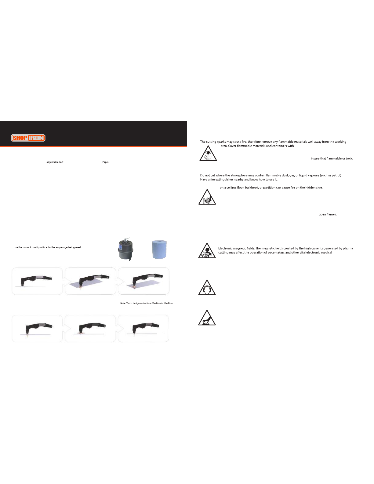
Fire hazard. Plasma cutting on closed containers, such as tanks,drums, or pipes, can cause them to explode. Flying
before doing any cutting.
Arc rays: harmful to people’s eyes and skin. Arc rays from the plasma cutting process produce in-
tense visible and invisible ultraviolet and infrared rays that can burn eyes and skin. Protect your eyes
safety garments. Protect others by installing adequate shields or
curtains.
•
welding gloves, appron, leg and foot protection whilst the plasma cutting operation is performed.
• Measures should be taken to protect people in or near the surrounding working area. Use protective
12
BUILT TO GET THE JOB DONE
Hold the torch at an angle to the work piece,
pull the trigger to start the arc and slowly
rotate it to an upright position.
When sparks are exiting from the bottom of
the work piece, the arc has pierced through the
material.
When the pierce is complete, proceed with
cutting.
This superheated air must be
treated with extreme caution.
● Piercing
4
SAFETY (Continued)
•
approved covers if unable to be moved from the welding area.
• Do not Plasma Cut closed containers such as tanks, drums, or pipes, unless they are
properly prepared according to the required Safety Standards to
vapors and substances are totally removed, these can cause an explosion even though the vessel
has been “cleaned”. Vent hollow castings or containers before heating, cutting or welding.
They may explode.
•
• Be alert that cutting sparks and hot materials
from cutting can easily go through small cracks and openings to adjacent areas. Be aware that cutting
Gas Cylinders. Do not cut in the vicinity of pressurised gas cylinders or in the presence of explosive
dust, gases or fumes. Gas cylinders contain gas under high pressure. If damaged, a cylinder can
explode. Because gas cylinders are normally part of the welding process, be sure to treat them
carefully. CYLINDERS can explode if damaged.
• Protect gas cylinders from excessive heat, mechanical shocks, physical damage, slag,
sparks, and arcs.
• Insure cylinders are held secure and upright to prevent tipping or falling over.
• Never allow the plasma nozzle or earth clamp to touch the gas cylinder, do not drape welding cables
over the cylinder.
• Never plasma cut on a pressurised gas cylinder, it will explode and kill you.
• Open the cylinder valve slowly and turn your face away from the cylinder outlet valve and gas regulator.
equipment.
• Wearers of Pacemakers and other Implanted Medical Devices should keep away.
• Implanted Medical Device wearers should consult their doctor and the device manufacturer before going
near any electric welding, cutting or heating operation.
Noise can damage hearing. Noise from some processes or equipment can damage hearing.
This machine does not directly produce noise exceeding 80dB. The plasma cutting/welding proce-
dure may produce noise levels beyond said limit; users must therefore implement all precautions
required by law. Wear approved ear protection if noise level is high.
Hot parts. Items being plasma cut generate and hold high heat and can cause severe burns.
Do not touch hot parts with bare hands. Allow a cooling period before working on the plasma
torch. Use insulated welding gloves and clothing to handle hot parts and prevent burns.
11
BUILT TO GET THE JOB DONE
● Air pressure and volume
Air pressure, ow rate and air quality are critical to quality plasma cutting and consumable life span.
The required air pressure and volume can vary from model to model and the manufacturer will provide the specs. The Shop Iron plasma
cutting machine air pressure is requires a minimum of 6CFM and The volume capacity of your compressor is
important, if you have a small compressor with exactly the same rating as the plasma, then the compressor will run continuously when you
are plasma cutting, a compressor with a l/min rating slightly higher than the plasma would be more adequate. If you are doing a lot of
cutting, cutting thick plate (same air consumption but slower cut speeds = longer cut time) then choose a compressor at 1.5 to 2 times the
plasma system requirement.
● Technique Tips
● Starting a cut
● Hand torch cutting technique
Good air quality is essential to quality plasma cutting and consumable life span.
Compressors take in air at atmospheric pressure and increase the pressure and store it in a tank. Humidity in the air is condensed in the tank
and in the airlines producing water, more so in humid environments. Moisture that forms in air lines has a tendency to condense into larger
drops when the air pressure decreases as it is entering the plasma torch. When these droplets enter into the high temperatures (as much as
19832°f) in the plenum of the torch, they immediately break down into oxygen and hydrogen, which alters the normal chemical content of
air in the torch. These elements will then dramatically change the plasma arc which causes the torch consumable parts to wear very quickly,
alters the shape of the nozzle orice, dramatically aecting cut quality in terms of edge squareness, dross formation, and edge smoothness.
Minimising the moisture in the air supply is absolutely critical to quality plasma cuts and longevity of consumable parts. As a minimum be
sure to drain the receiver (tank) on the air compressor at least daily. Most air plasma systems from reputable manufacturers have an on
board particulate lter and or a coalescing lter with an auto drain that will remove some moisture from the air supply. For home workshop
and light industrial users the on board air lter is adequate. Most situations however will require additional ltration to prevent moisture
from aecting the quality of the plasma cutter and in most cases it is recommended to install a sub micronic particulate lter that is
designed to trap water through absorption. This style of lter has a replaceable lter cartridge that absorbs water and must be changed
after it is near saturation, it should be installed close as possible to the air intake of the plasma cutter.
• It is easier to pull the torch through the cut than to push it.
• To cut thin material reduce the amperage until you get the best quality cut.
•
• For Straight cuts use a straight edge or cutting buggy as a guide. For circles,
use a template or circle cutting attachment.
• Check that the front end consumable parts of the plasma cutting torch
are in good condition.
Sub Micronic Filter example
Filter Element example
Hold the torch vertical at the edge of the work
piece
Pull the trigger to start the pilot arc.
The cutting arc will initiate when the torch tip
is close enough to the work piece. Start cutting
on the edge until the arc has cut completely
through.
Then, proceed with the cut.
When cutting make sure that sparks are exiting
from the bottom of the work piece.
If sparks are spraying up from the work piece,
you are moving the torch too fast, or you don't
have enough amps set.
Hold the torch vertical and watch the arc as it
cuts along the line.
Note: The dryer the air, the longer your consumable life!!

5
TROUBLE SHOOTING
For your safety and to avoid Electrical Shock, please observe all safety notes and precautions
detailed in this manual.
Note:
• Our equipment as described in this manual conforms to all applicable rules and regulations of the
‘LowVoltage Directive’ (European Council Directive 73/23/EEC) as set out and amended by Council
Directive 93/68/EEC) and to the National legislation for the enforcement of this Directive.
• Our equipment as described in this manual conforms to all applicable rules and regulations of the
European Council Directive 89/336/EEC, (EMC Directive) and to the National legislation for he
enforcement of this Directive.
CAUTION
1. Working Environment.
1.1 The environment in which this welding equipment is installed must be free of grinding dust, corrosive
ials etc, and at no more than maximum of 80% humidity.
1.2 When using the machine outdoors protect the machine from direct sun light, rain water and snow etc;
the temperature of working environment should be maintained within -14°F to +104°F..
1.3 Keep this equipment 1ft distant from the wall.
1.4 Ensure the working environment is well ventilated.
2. Safety Tips.
2.1 Ventilation
This equipment is small-sized, compact in structure, and of excellent performance in amperage output.
The fan is used to dissipate heat generated by this equipment during the welding operation.
Important: Maintain good ventilation of the louvers of this equipment. The minimum distance between
this equipment and any other objects in or near the working area should be 1ft. Good ventilation is
of critical importance for the normal performance and service life of this equipment.
2.2 Thermal Overload protection.
Should the machine be used to an excessive level, or in high temperature environment, poorly
ventilated area or if the fan malfunctions the Thermal Overload Switch will be activated and the
machine will cease to operate. Under this circumstance, leave the machine switched on to keep the
built-in fan working to bring down the temperature inside the equipment. The machine will be ready for
use again when the internal temperature reaches safe level.
2.3 Over-Voltage Supply
Regarding the power supply voltage range of the machine, please refer to “Main parameter” table.
This equipment is of automatic voltage compensation, which enables the maintaining of the voltage
range within the given range. In case that the voltage of input power supply amperage exceeds the
stipulated value, it is possible to cause damage to the components of this equipment. Please ensure
your primary power supply is correct.
2.4 Do not come into contact with the output terminals while the machine is in operation. An electric shock
may possibly occur.
MAINTENANCE
Exposure to extremely dusty, damp, or corrosive air is damaging to the welding machine. In order to
prevent any possible failure or fault of this welding equipment, clean the dust at regular intervals with clean and
dry compressed air of required pressure.
Please note that: lack of maintenance can result in the cancellation of the guarantee; the guarantee of this welding
made sealing of the machine without the consent of an authorized representative of the manufacturer.
10
BUILT TO GET THE JOB DONE
Standard rule of thumb is the thicker the material the more amperage required.
On thick material, set the machine to full output and vary your travel speed. On thinner material, you need to turn down the amperage and
change to a lower-amperage tip to maintain a narrow kerf. The kerf is the width of the cut material that is removed during cutting.
Amperage and speed are critical to producing a good quality cut. The faster you move (especially on aluminium), the cleaner your cut will
be. To determine if you're going too fast or too slow, visually follow the arc that is coming from the bottom of the cut. The arc should exit
the material at a slight angle away from the direction of travel. If it's going straight down, that means you're going too slow, and you'll have
an unnecessary buildup of dross or slag. If you go too fast, it will start spraying back onto the surface of the material without cutting all the
way through. Because the arc trails at an angle, at the end of a cut, slow your cutting speed and angle the torch in to cut through the last bit
of metal.
-
easiest way to reduce bevel is by cutting at the proper speed and height for the material and amperage that is being cut.
Correct torch height and square
to the material.
Minimum bevel & equal bevel
Longest consumable life
Torch angled to the material.
Unequal bevel, one side may be
excessively beveled.
Torch height too high.
Excessive bevel, plasma stream
may not cut all the way through
the material
Torch height too low.
Reverse bevel. Tip may
contact the work and short out
or damage the tip.
-
which maintains a narrow plasma stream at lower settings for use on thin-gauge material. Using a 25 amp tip at an 60 amp setting will blow
Electrons arc across the gap, ionizing and super
heating the air creating the plasma stream. The electrode contains an insert in the end made of a highly conductive material called hafnium.
This insert erodes with use and develops a pit in the end of the electrode, when the pit becomes too much poor quality cuts will result and
necessitate replacement of the electrode.
New Tip Worn Tip
New Electrode Worn electrode
● Amperage
● Speed
● Direction
● Torch tip height & position
● Tip size and condition
● Electrode condition
69
Plasma cutters work by passing an electric arc through a gas that is passing through a constricted opening. The gas can be air, ni-
trogen, argon, oxygen. etc. The electric arc elevates the temperature of the gas to the point that it enters a 4th state of matter. We
part of the circuit, the electrical conductivity of the plasma causes the arc to transfer to the work. The restricted opening (nozzle)
the gas passes through causes it to squeeze by at a high speed, like air passing through a venturi in a carburettor. This high speed
gas cuts through the molten metal.
Plasma cutting was invented as the result of trying to develop a better welding process. Many improvements then led to making
How a plasma cutter works:
Basic plasma cutters use electricity to superheat air into plasma (the 4th state of matter), which is then blown through the metal
to be cut. Plasma cutters require a compressed air supply and AC power to operate.
Operation:
electrode and through the hole of the cutting nozzle.
maintain aconstant current through the joint.) Electrons arc across the gap, ionizing and super heating the air
creating a plasma stream.
Notes:
The nozzle and electrode require periodic replacement. The electrode has an insert of tough high conductive material such as
longer life of electrodes and nozzles, in short clean dry air gives longer parts life, the cleaner and dryer the better. We recommend
use of a Plasma Air Filter.
What kinds of materials can the plasma cut?
Virtually any metal can be plasma cut including steel, stainless steel, aluminium, brass, copper, etc. Any thickness from 30 gauge
through 13/16"can be cut, depending on the power of the plasma cutter used.
How Does Plasma Cutting Compare to Oxy-fuel (gas) cutting?
Plasma cutting can be performed on any type of conductive metal - mild steel, aluminium and stainless are some
examples. With mild steel, operators will experience faster, thicker cuts than with alloys. Oxy-fuel cuts by burning, or
oxidizing the metal it is severing. It is therefore limited to steel and other ferrous metals which support the oxidizing
process. Metals like aluminium and stainless steel form an oxide that inhibits further oxidization, making conventional
oxy-fuel cutting impossible. Plasma cutting however does not rely on oxidation to work and thus it can cut aluminium, stainless
for the plasma gas. In most shops, compressed air is readily available, and thus plasma does not require fuel gas and compressed
oxygen for operation. Plasma cutting is typically easier for the novice to master, and on thinner materials, plasma cutting is much
faster than oxy-fuel cutting. However, for heavy sections of steel (1" and greater), oxy-fuel is still preferred since oxy-fuel is typi-
cally faster and, for heavier plate applications high powered plasma machines are required for plasma cutting applications.
What are the limitations to Plasma Cutting? Where is Oxyfuel preferred?
The plasma cutting machines are typically more expensive than oxy/acetylene. Also, oxy/acetylene does not require
access to electrical power or compressed air which may make it a more convenient method for some users. Oxyfuel can generally
cut thicker sections (>63/64 inch) of steel more quickly than plasma
Electrode
Nozzle
Plasma Stream
Electrode Insert
Shield Cup
AIR PLASMA CUTTING TECHNOLOGY
BUILT TO GET THE JOB DONE
5) Correct amperage and travel speed are
important and relevant to material thickness
and are correct when sparks are exiting from
the work piece.
If sparks are spraying up from the work piece
travel speed is too fast.
6)
seconds to cool the torch head.
2) Connect the Earth Clamp securely to the
work piece or the work bench.
3) Place and hold the torch vertical at the
edge of the plate
4) Pull the trigger to energise the pilot arc.
The cutting arc will start when the nozzle is
moved closer to the edge of the work piece.
When the cutting arc has cut through the
edge of the plate start moving evenly in the
direction you wish to cut,
1) Wear your safety gear. Generally you want the same
type of protective gear as when welding. Plasma has
high arc voltage if the job or bench is wet and you place
your hand or arm on it you can become part of the cir-
cuit and receive a shock, be sure you are wearing leather
gloves, Full lenght pants and covered shoes, Wear eye
protection a #5 shade is the minimum eye protection
with other shades required depending on amperage. A
face shield is also recommended,
especially suitable if your hands are unsteady, or if you wish to use a straight edge guide or
pattern guide. It also helps extend tip life.
Cut Quality
A clean cut depends on several factors:
●amperage
●travel speed
●tip height & position
●tip and electrode quality
●air pressure and quality
●technique
The best quality cut will be produced when all these variables are set correctly for the material thickness and type
of material being cut.
Poor quality cut
Good quality cut
Please note: Torch handle and shape varies from Machine to
Machine.

1
6
78
910
11
5
4
2
3
7 8
FEATURES AND SPECIFICATIONS (continued)
SETUP
Mild steel: 1/4"
Sever: 1/2"
Power Supply / Phases (V-Ph) 115/230V - 1 +/- 15%
Rated input Power (KVA) 5.5-230V
Rated Output Current 20-30A
Duty Cycle @ 104ºF 35% @30A - 230V
Efficiency 85%
Open Circuit Voltage 96V
Protection Class IP21S
Cutting Capacity*
Rated: 1/4" (6.4 mm)
Sever: 1/2" (12.7 mm)
Air Supply: Clean, dry, oil-free
compressed air
Recommended Input 6.0 SCFM @ 75 PSI
Pressure/Flow
Size (Inches) 20" x 12" x 16"
Weight (Pounds) 20.25
Compliant to CAN/CSA E60974-1
*mild steel
TECHNICAL DATAFEATURES
CUTTING CAPACITY
• POWERFUL AND RELIABLE IGBT INVERTER
TECHNOLOGY DELIVERS 30 AMPS AT A 35%
DUTY CYCLE
• DUAL VOLTAGE-SENSING TECHNOLOGY (115V
OR 230V) LETS YOU PLUG INTO ANY COMMON
POWER SUPPLY WITH INCLUDED ADAPTER
• CUTS MILD STEEL, STAINLESS, BRASS,
ALUMINUM AND OTHER CONDUCTIVE
MATERIALS
• LOW FREQUENCY, PILOT ARC SYSTEM FOR
INSTANT STARTS AND EASE OF USE WHEN
CUTTING RUSTY MATERIAL AND WILL
NOT INTERFERE WITH OTHER ELECTRICAL
SYSTEMS INCLUDING TELEPHONE OR
COMPUTER
• SELF-RESETTING THERMAL OVERLOAD
PROTECTION WITH INDICATOR LIGHT
AUTOMATICALLY SHUTS OFF TO AVOID
OVERHEATING
• ADJUSTABLE AIR FILTER/ PRESSURE
REGULATOR
• LIGHTWEIGHT AND PORTABLE LESS THAN
21 POUNDS!
• FAN COOLED
BUILT TO GET THE JOB DONE
1. 12 ft. TRF45 Plasma Torch
(Direct Connect)
2. 115/230V Power Adapter
3. Work Clamp
4. Work Clamp Connection
5. Air Pressure Gauge
6. Current Adjustment
7. Power Light
8. Overload Light
9. Cutting Operation Light
10. Trigger Latch Operation
11. Cutting Mode Switch
12. Air Regulator
13. Control PCB
14. Magnetic Valve
15. Power Switch
16. Input Power Cable
12
14
13 15
16
FEATURES AND SPECIFICATIONS
BUILT TO GET THE JOB DONE
(1) Connect the earth lead to the output terminal of the machine and tighten.
(2) Connect the air supply to the air connection located at the rear of the machine.
Turn on the air supply
(3)
located at the rear of the machine.
(4) Select 2T / 4T operation
Operating procedure using the 2T / 4T Function with Plasma torch.
Set torch operation 2T / 4T.
• When 2T operation is selected press trigger Arc starts, release trigger Arc stops.
• When 4T operation is selected press and release trigger Arc starts,
press and release trigger Arc stops.
(5) Set amperage dial.
(3) Connect the machine to the
correct power supply and switch on
located at the rear of the machine..
(2) Connect the air supply to the air
connection located at the rear of the
machine. Turn on the air supply.
(4) select 2T or 4T torch control .
(1) Connect the earth lead to the
output terminal of the machine and
tighten.
(5) Set the amperage dial
Table of contents
Popular Welding System manuals by other brands


Hobart Welding Products
Hobart Welding Products AirForce 375 owner's manual

GF
GF MSA 330 instruction manual

Hakko Electronics
Hakko Electronics FX-888D instruction manual

Abicor Binzel
Abicor Binzel ABIPLAS WELD 100 W operating instructions

EWM
EWM Taurus 355 Basic TDM operating instructions

Thermal Dynamics
Thermal Dynamics PakMaster 100 XL plus operating manual


