TEAM WELDER MIG 250 S User manual

Operating instructions
EN
Welding machine
MIG 250 S
MIG 300 S
299-030200-TWD01
25.09.2015

General information
CAUTION
Read the operating instructions!
The operating instructions provide an introduction to the safe use of the products.
•Read the operating instructions for all system components.
•Observe the applicable accident prevention regulations.
•Observe all country-specific statutory provisions.
•Have confirmed by signature if necessary.
In the event of queries on installation, commissioning, operation or special conditions at the
installation site, or on usage, please contact your sales partner or our
customer service department on +49 2623 9276400.
A list of authorised sales partners can be found at www.teamwelder.com.
Liability in conjunction with the operation of this system is explicitly limited to the functioning of
the system. Any further liability, regardless of which type, is explicitly excluded. This liability
disclaimer is regarded as having been accepted by the user when the system is commissioned.
The manufacturer can neither monitor the compliance with these instructions nor the conditions
and methods employed during the installation, operation, use and maintenance of the machine.
An incorrectly performed installation can lead to material damage and injure persons as a result.
Therefore, we assume no responsibility or liability for losses, damages or costs arising from
erroneous installation, improper operation or incorrect use and maintenance, or any
consequences in conjunction thereof.
TEAMWELDER Germany GmbH
Sälzerstraße 20a
D-56235 Ransbach-Baumbach
Deutschland / Germany
The copyright to this document remains the property of the manufacturer.
Reprinting, including extracts, only permitted with written approval.
The content of this document has been prepared and reviewed with all reasonable care. The information
provided is subject to change; errors excepted.

Contents
Notes on the use of these operating instructions
299-030200-TWD01
25.09.2015
3
1 Contents
1Contents..................................................................................................................................................3
2Safety instructions.................................................................................................................................5
2.1 Notes on the use of these operating instructions ..........................................................................5
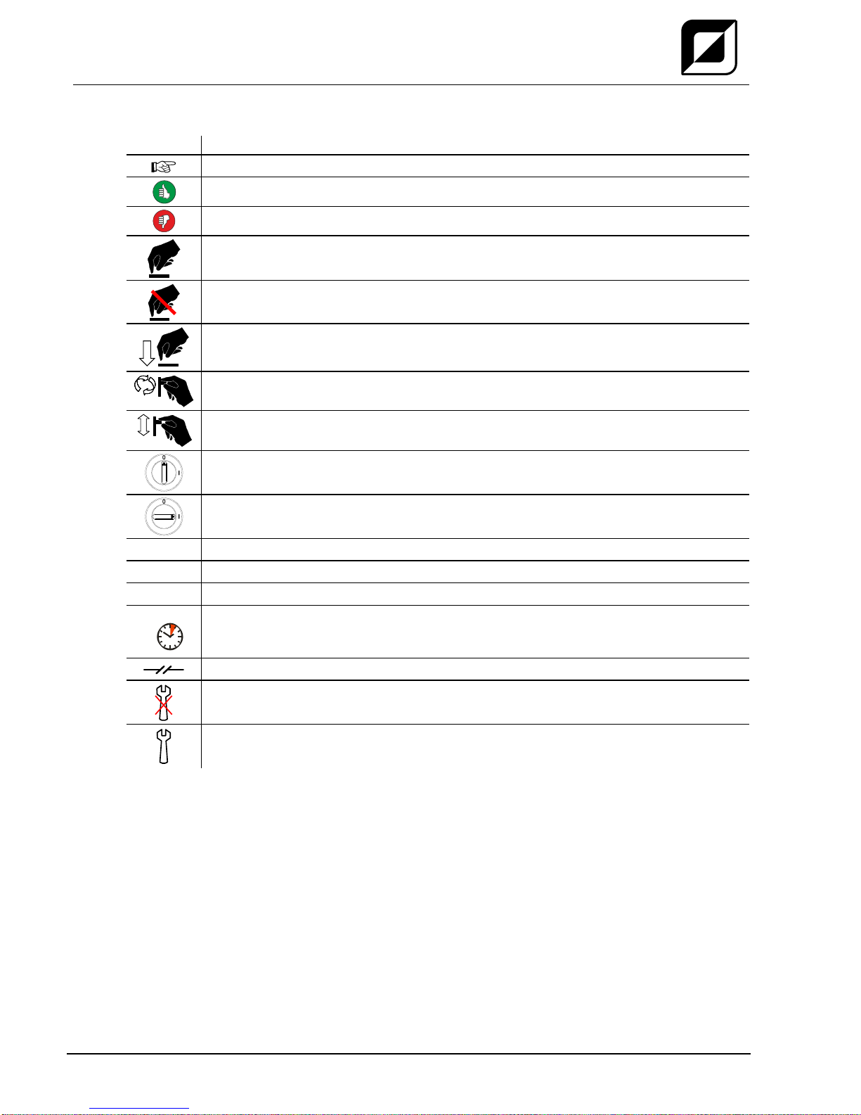
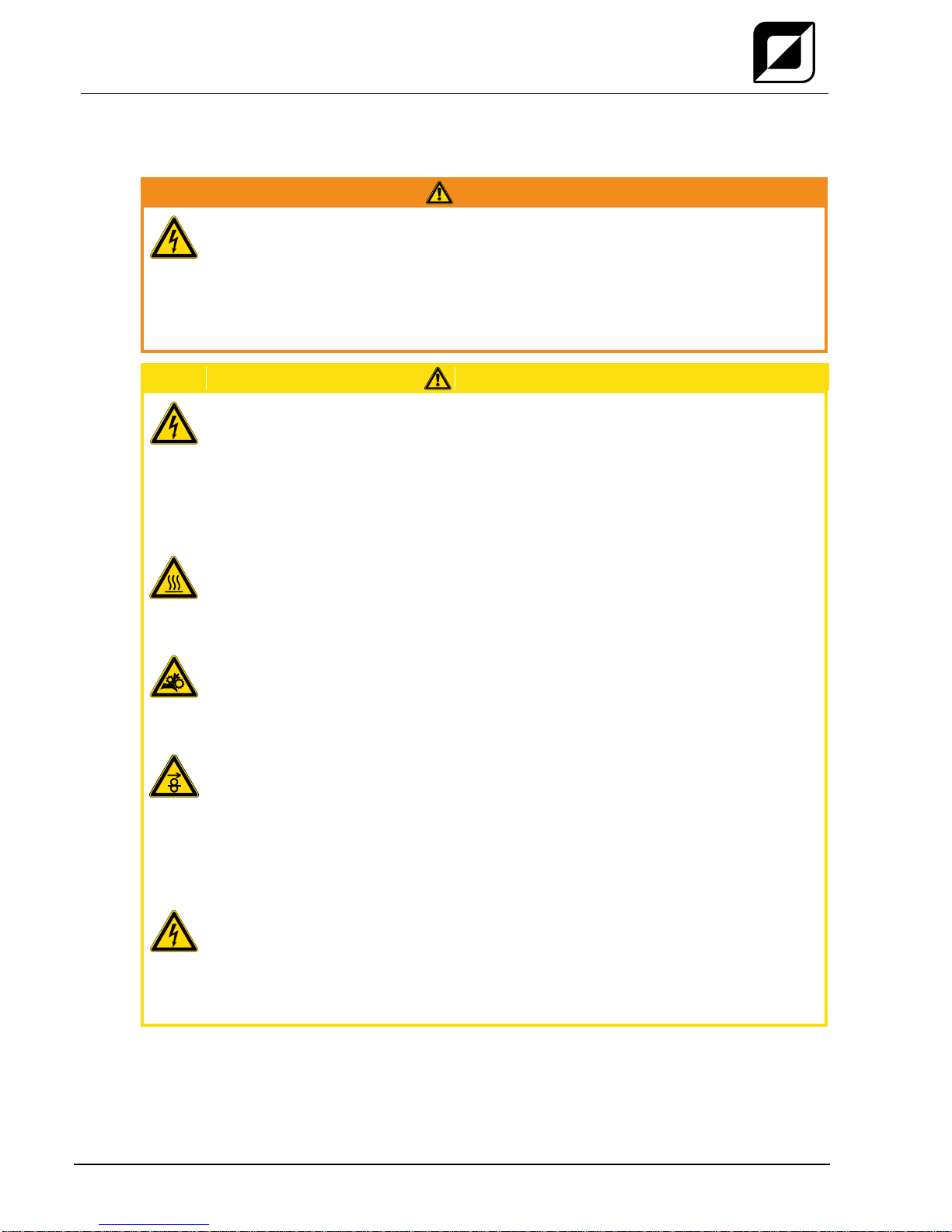
2.2 Explanation of icons.......................................................................................................................6
2.3 General ..........................................................................................................................................7
2.4 Transport and installation ............................................................................................................11
2.4.1 Ambient conditions .......................................................................................................12
2.4.1.1 In operation ...................................................................................................12
2.4.1.2 Transport and storage...................................................................................12
3Intended use.........................................................................................................................................13
3.1 Applications..................................................................................................................................13
3.1.1 MIG/MAG standard welding .........................................................................................13
3.2 Documents which also apply .......................................................................................................14
3.2.1 Warranty.......................................................................................................................14
3.2.2 Declaration of Conformity.............................................................................................14
3.2.3 Welding in environments with increased electrical hazards.........................................14
3.2.4 Service documents (spare parts and circuit diagrams)................................................14
3.2.5 Calibration/Validation....................................................................................................14
4Machine description –quick overview ..............................................................................................15
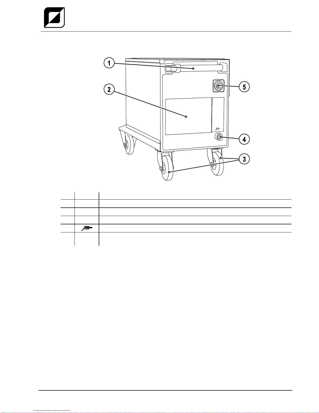
4.1 Front view ....................................................................................................................................15
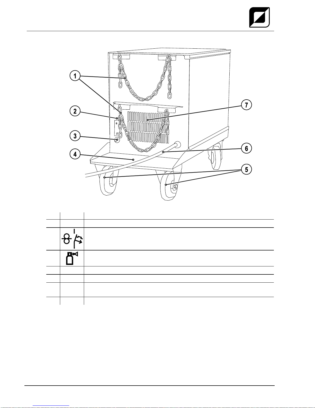
4.2 Rear view.....................................................................................................................................16
4.3 Inside view ...................................................................................................................................17
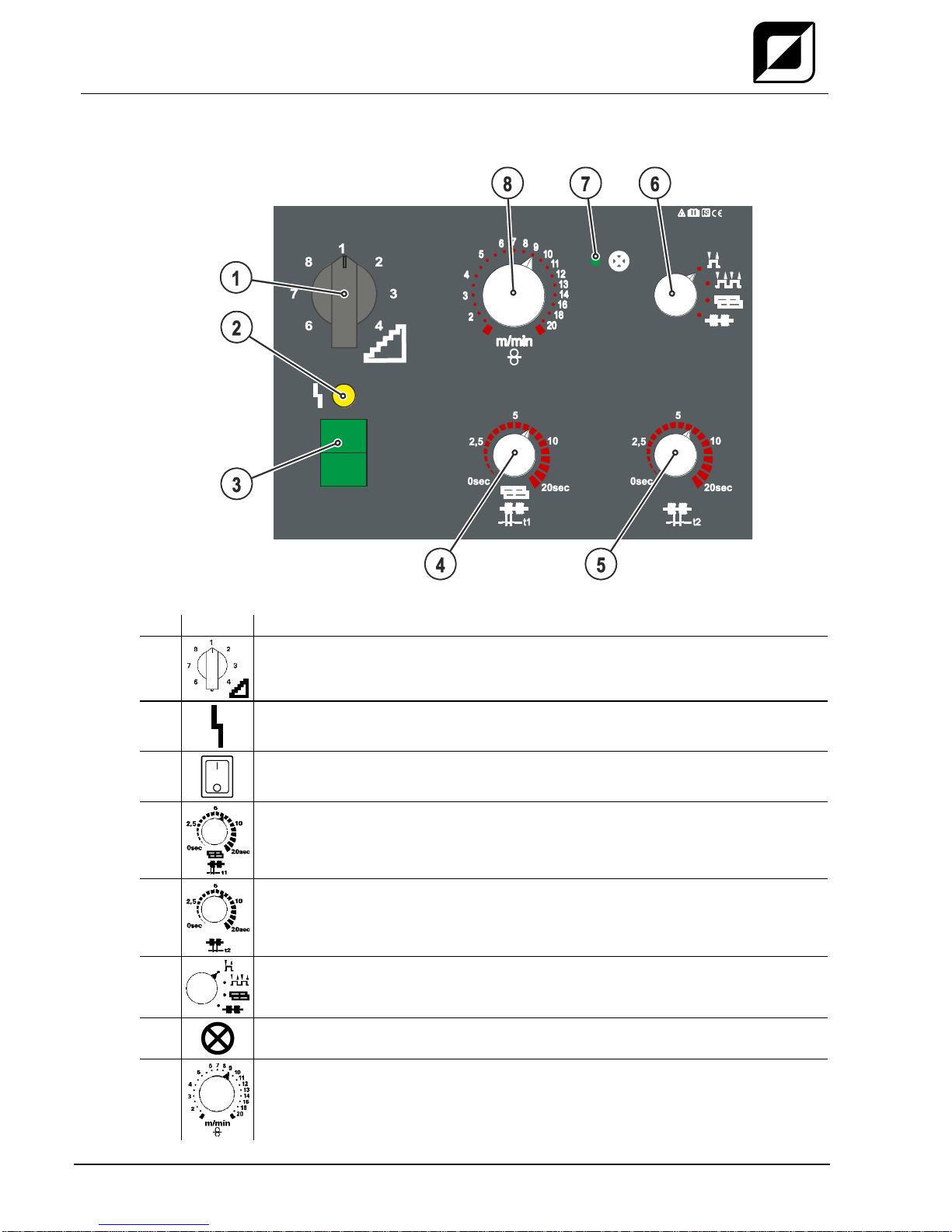
4.4 Machine control –Operating elements........................................................................................18
4.4.1 MIG 250 S ....................................................................................................................18
4.4.2 MIG 300 S ....................................................................................................................19
5Design and function.............................................................................................................................20
5.1 General ........................................................................................................................................20
5.2 Installation....................................................................................................................................22
5.3 Machine cooling...........................................................................................................................22
5.4 Workpiece lead, general..............................................................................................................22
5.5 Mains connection.........................................................................................................................23
5.5.1 Mains configuration ......................................................................................................23
5.6 Welding torch and workpiece line connection .............................................................................24
5.7 Shielding gas supply (shielding gas cylinder for welding machine).............................................26
5.7.1 Connection ...................................................................................................................27
5.7.2 Setting the shielding gas quantity.................................................................................28
5.8 Wire feed......................................................................................................................................29
5.8.1 Open the protective flap of the wire feeder ..................................................................29
5.8.2 Inserting the wire spool.................................................................................................29
5.8.3 Changing the wire feed rollers......................................................................................30
5.8.4 Inching the wire electrode ............................................................................................32
5.8.5 Spool brake setting.......................................................................................................33
5.9 MIG/MAG operating point............................................................................................................34
5.10 MIG/MAG functional sequences / operating modes....................................................................34
5.10.1 Explanation of signs and functions...............................................................................34
6Maintenance, care and disposal.........................................................................................................38
6.1 General ........................................................................................................................................38
6.2 Maintenance work, intervals ........................................................................................................38
6.2.1 Daily maintenance tasks...............................................................................................38
6.2.1.1 Visual inspection...........................................................................................38
6.2.1.2 Functional test...............................................................................................38
6.2.2 Monthly maintenance tasks..........................................................................................38
6.2.2.1 Visual inspection...........................................................................................38
6.2.2.2 Functional test...............................................................................................38
6.2.3 Annual test (inspection and testing during operation)..................................................39

Contents
Notes on the use of these operating instructions
4
299-030200-TWD01
25.09.2015
6.3 Disposing of equipment................................................................................................................39
6.3.1 Manufacturer's declaration to the end user ..................................................................39
6.4 Meeting the requirements of RoHS..............................................................................................39
7Rectifying faults....................................................................................................................................40
7.1 Checklist for rectifying faults ........................................................................................................40
8Technical data.......................................................................................................................................41
8.1 MIG 250 S, 300 S.........................................................................................................................41
9Accessories ..........................................................................................................................................42
9.1 Internet.........................................................................................................................................42
10 Replaceable parts.................................................................................................................................43
10.1 Wire feed rollers...........................................................................................................................43
10.1.1 Wire feed rollers for steel wire......................................................................................43
10.1.2 Wire feed rollers for aluminium wire .............................................................................43

Safety instructions
Notes on the use of these operating instructions
299-030200-TWD01
25.09.2015
5
2 Safety instructions
2.1 Notes on the use of these operating instructions
DANGER
Working or operating procedures which must be closely observed to prevent imminent
serious and even fatal injuries.
•Safety notes include the "DANGER" keyword in the heading with a general warning symbol.
•The hazard is also highlighted using a symbol on the edge of the page.
WARNING
Working or operating procedures which must be closely observed to prevent serious
and even fatal injuries.
•Safety notes include the "WARNING" keyword in the heading with a general warning
symbol.
•The hazard is also highlighted using a symbol in the page margin.
CAUTION
Working or operating procedures which must be closely observed to prevent possible
minor personal injury.
•The safety information includes the "CAUTION" keyword in its heading with a general
warning symbol.
•The risk is explained using a symbol on the edge of the page.
CAUTION
Working and operating procedures which must be followed precisely to avoid damaging
or destroying the product.
•The safety information includes the "CAUTION" keyword in its heading without a general
warning symbol.
•The hazard is explained using a symbol at the edge of the page.
Special technical points which users must observe.
Instructions and lists detailing step-by-step actions for given situations can be recognised via bullet
points, e.g.:
•Insert the welding current lead socket into the relevant socket and lock.

Safety instructions
Explanation of icons
6
299-030200-TWD01
25.09.2015
2.2 Explanation of icons
Symbol
Description
Special technical points which users must observe.
Correct
Wrong
Press
Do not press
Press and keep pressed
Turn
Switch
Switch off machine
Switch on machine
ENTER
enter the menu
NAVIGATION
Navigating in the menu
EXIT
Exit the menu
4 s
Time display (example: wait 4s/press)
Interruption in the menu display (other setting options possible)
Tool not required/do not use
Tool required/use

Safety instructions
General
299-030200-TWD01
25.09.2015
7
2.3 General
DANGER
Electromagnetic fields!
The power source may cause electrical or electromagnetic fields to be produced which
could affect the correct functioning of electronic equipment such as IT or CNC devices,
telecommunication lines, power cables, signal lines and pacemakers.
•Observe the maintenance instructions - See 6 Maintenance, care and disposal chapter!
•Unwind welding leads completely!
•Shield devices or equipment sensitive to radiation accordingly!
•The correct functioning of pacemakers may be affected (obtain advice from a doctor if
necessary).
Do not carry out any unauthorised repairs or modifications!
To avoid injury and equipment damage, the unit must only be repaired or modified by
specialist, skilled persons!
The warranty becomes null and void in the event of unauthorised interference.
•Appoint only skilled persons for repair work (trained service personnel)!
Electric shock!
Welding machines use high voltages which can result in potentially fatal electric shocks
and burns on contact. Even low voltages can cause you to get a shock and lead to
accidents.
•Do not touch any live parts in or on the machine!
•Connection cables and leads must be free of faults!
•Switching off alone is not sufficient!
•Place welding torch and stick electrode holder on an insulated surface!
•The unit should only be opened by specialist staff after the mains plug has been
unplugged!
•Only wear dry protective clothing!
•Wait for 4 minutes until the capacitors have discharged!
WARNING
Risk of injury due to radiation or heat!
Arc radiation results in injury to skin and eyes.
Contact with hot workpieces and sparks results in burns.
•Use welding shield or welding helmet with the appropriate safety level (depending on the
application)!
•Wear dry protective clothing (e.g. welding shield, gloves, etc.) according to the relevant
regulations in the country in question!
•Protect persons not involved in the work against arc beams and the risk of glare using
safety curtains!
Explosion risk!
Apparently harmless substances in closed containers may generate excessive pressure
when heated.
•Move containers with inflammable or explosive liquids away from the working area!
•Never heat explosive liquids, dusts or gases by welding or cutting!

Safety instructions
General
8
299-030200-TWD01
25.09.2015
WARNING
Smoke and gases!
Smoke and gases can lead to breathing difficulties and poisoning. In addition, solvent
vapour (chlorinated hydrocarbon) may be converted into poisonous phosgene due to
the ultraviolet radiation of the arc!
•Ensure that there is sufficient fresh air!
•Keep solvent vapour away from the arc beam field!
•Wear suitable breathing apparatus if appropriate!
Fire hazard!
Flames may arise as a result of the high temperatures, stray sparks, glowing-hot parts
and hot slag produced during the welding process.
Stray welding currents can also result in flames forming!
•Check for fire hazards in the working area!
•Do not carry any easily flammable objects such as matches or lighters.
•Keep appropriate fire extinguishing equipment to hand in the working area!
•Thoroughly remove any residue of flammable substances from the workpiece before
starting welding.
•Only continue work on welded workpieces once they have cooled down.
Do not allow to come into contact with flammable material!
•Connect welding leads correctly!
Risk of accidents if these safety instructions are not observed!
Non-observance of these safety instructions is potentially fatal!
•Carefully read the safety information in this manual!
•Observe the accident prevention regulations in your country.
•Inform persons in the working area that they must observe the regulations!
Danger when coupling multiple power sources!
Coupling multiple power sources in parallel or in series has to be carried out by
qualified personnel and in accordance with the manufacturer's guidelines. Before
bringing the power sources into service for arc welding operations, a test has to verify
that they cannot exceed the maximum allowed open circuit voltage.
•Connection of the machine may be carried out by qualified personnel only!
•When decommissioning individual power sources, all mains and welding current leads have
to be safely disconnected from the welding system as a whole. (Danger due to inverse
voltages!)
•Do not couple welding machines with pole reversing switch (PWS series) or machines for
AC welding, as a minor error in operation can cause the welding voltages to be combined.
CAUTION
Noise exposure!
Noise exceeding 70 dBA can cause permanent hearing damage!
•Wear suitable ear protection!
•Persons located within the working area must wear suitable ear protection!

Safety instructions
General
299-030200-TWD01
25.09.2015
9
CAUTION
Obligations of the operator!
The respective national directives and laws must be observed for operation of the
machine!
•National implementation of the framework directive (89/391/EWG), as well as the
associated individual directives.
•In particular, directive (89/655/EWG), on the minimum regulations for safety and health
protection when staff members use equipment during work.
•The regulations regarding work safety and accident prevention for the respective country.
•Setting up and operating the machine according to IEC 60974-9.
•Check at regular intervals that users are working in a safety-conscious way.
•Regular checks of the machine according to IEC 60974-4.
Damage due to the use of non-genuine parts!
The manufacturer's warranty becomes void if non-genuine parts are used!
•Only use system components and options (power sources, welding torches, electrode
holders, remote controls, spare parts and replacement parts, etc.) from our range of
products!
•Only insert and lock accessory components into the relevant connection socket when the
machine is switched off.
Damage to the machine due to stray welding currents!
Stray welding currents can destroy protective earth conductors, damage equipment and
electronic devices and cause overheating of components leading to fire.
•Make sure all welding leads are securely connected and check regularly.
•Always ensure a proper and secure electrical connection to the workpiece!
•Set up, attach or suspend all conductive power source components like casing, transport
vehicle and crane frames so they are insulated!
•Do not place any other electronic devices such as drillers or angle grinders, etc., on the
power source, transport vehicle or crane frames unless they are insulated!
•Always put welding torches and electrode holders on an insulated surface when they are
not in use!
Mains connection
Requirements for connection to the public mains network
High-performance machines can influence the mains quality by taking current from the mains
network. For some types of machines, connection restrictions or requirements relating to the
maximum possible line impedance or the necessary minimum supply capacity at the interface
with the public network (Point of Common Coupling, PCC) can therefore apply. In this respect,
attention is also drawn to the machines' technical data. In this case, it is the responsibility of
the operator, where necessary in consultation with the mains network operator, to ensure that
the machine can be connected.

Safety instructions
General
10
299-030200-TWD01
25.09.2015
CAUTION
EMC Machine Classification
In accordance with IEC 60974-10, welding machines are grouped in two electromagnetic
compatibility classes - See 8 Technical data chapter:
Class A machines are not intended for use in residential areas where the power supply comes
from the low-voltage public mains network. When ensuring the electromagnetic compatibility of
class A machines, difficulties can arise in these areas due to interference not only in the supply
lines but also in the form of radiated interference.
Class B machines fulfil the EMC requirements in industrial as well as residential areas,
including residential areas connected to the low-voltage public mains network.
Setting up and operating
When operating arc welding systems, in some cases, electro-magnetic interference can occur
although all of the welding machines comply with the emission limits specified in the standard.
The user is responsible for any interference caused by welding.
In order to evaluate any possible problems with electromagnetic compatibility in the
surrounding area, the user must consider the following: (see also EN 60974-10 Appendix A)
•Mains, control, signal and telecommunication lines
•Radios and televisions
•Computers and other control systems
•Safety equipment
•The health of neighbouring persons, especially if they have a pacemaker or wear a hearing
aid
•Calibration and measuring equipment
•The immunity to interference of other equipment in the surrounding area
•The time of day at which the welding work must be carried out
Recommendations for reducing interference emission
•Mains connection, e.g. additional mains filter or shielding with a metal tube
•Maintenance of the arc welding equipment
•Welding leads should be as short as possible and run closely together along the ground
•Potential equalization
•Earthing of the workpiece. In cases where it is not possible to earth the workpiece directly,
it should be connected by means of suitable capacitors.
•Shielding from other equipment in the surrounding area or the entire welding system

Safety instructions
Transport and installation
299-030200-TWD01
25.09.2015
11
2.4 Transport and installation
WARNING
Incorrect handling of shielding gas cylinders!
Incorrect handling of shielding gas cylinders can result in serious and even fatal injury.
•Observe the instructions from the gas manufacturer and in any relevant regulations
concerning the use of compressed air!
•Place shielding gas cylinders in the holders provided for them and secure with fixing
devices.
•Avoid heating the shielding gas cylinder!
Risk of accident due to improper transport of machines that may not be lifted!
Do not lift or suspend the machine! The machine can fall down and cause injuries! The
handles and brackets are suitable for transport by hand only!
•The machine may not be lifted by crane or suspended!
CAUTION
Risk of tipping!
There is a risk of the machine tipping over and injuring persons or being damaged itself
during movement and set up. Tilt resistance is guaranteed up to an angle of 10°
(according to IEC 60974-1).
•Set up and transport the machine on level, solid ground.
•Secure add-on parts using suitable equipment.
Damage due to supply lines not being disconnected!
During transport, supply lines which have not been disconnected (mains supply leads,
control leads, etc.) may cause hazards such as connected equipment tipping over and
injuring persons!
•Disconnect supply lines!
CAUTION
Equipment damage when not operated in an upright position!
The units are designed for operation in an upright position!
Operation in non-permissible positions can cause equipment damage.
•Only transport and operate in an upright position!

Safety instructions
Transport and installation
12
299-030200-TWD01
25.09.2015
2.4.1 Ambient conditions
CAUTION
Installation site!
The machine must not be operated in the open air and must only be set up and
operated on a suitable, stable and level base!
•The operator must ensure that the ground is non-slip and level, and provide sufficient
lighting for the place of work.
•Safe operation of the machine must be guaranteed at all times.
CAUTION
Equipment damage due to dirt accumulation!
Unusually high quantities of dust, acid, corrosive gases or substances may damage the
equipment.
•Avoid high volumes of smoke, vapour, oil vapour and grinding dust!
•Avoid ambient air containing salt (sea air)!
Non-permissible ambient conditions!
Insufficient ventilation results in a reduction in performance and equipment damage.
•Observe the ambient conditions!
•Keep the cooling air inlet and outlet clear!
•Observe the minimum distance of 0.5 m from obstacles!
2.4.1.1 In operation
Temperature range of the ambient air:
•-25 °C to +40 °C
Relative air humidity:
•Up to 50% at 40 °C
•Up to 90% at 20 °C
2.4.1.2 Transport and storage
Storage in an enclosed space, temperature range of the ambient air:
•-30 °C to +70 °C
Relative air humidity
•Up to 90% at 20 °C

Intended use
Applications
299-030200-TWD01
25.09.2015
13
3 Intended use
WARNING
Hazards due to improper usage!
Hazards may arise for persons, animals and material objects if the equipment is not
used correctly. No liability is accepted for any damages arising from improper usage!
•The equipment must only be used in line with proper usage and by trained or expert staff!
•Do not modify or convert the equipment improperly!
3.1 Applications
3.1.1 MIG/MAG standard welding
Metal arc welding using a wire electrode, where the arc and the weld pool are shielded from the
atmosphere with inert (MIG) or active (MAG) gasses or gas mixtures.

Intended use
Documents which also apply
14
299-030200-TWD01
25.09.2015
3.2 Documents which also apply
3.2.1 Warranty
For more information on the warranty topic refer to the included CD-ROM or the website:
www.teamwelder.com.
3.2.2 Declaration of Conformity
The labelled machine complies with EC directives in terms of its design and
construction:
•EC Low Voltage Directive (2006/95/EC)
•EC EMC Directive (2004/108/EC)
In case of unauthorised changes, improper repairs, non-compliance with specified deadlines for "Arc
Welding Equipment –Inspection and Testing during Operation", and/or prohibited modifications which
have not been explicitly authorised by TEAMWELDER, this declaration shall be voided. An original
document of the specific declaration of conformity is included with every product.
3.2.3 Welding in environments with increased electrical hazards
In compliance with IEC / DIN EN 60974, VDE 0544 the machines can be used in
environments with an increased electrical hazard.
3.2.4 Service documents (spare parts and circuit diagrams)
DANGER
Do not carry out any unauthorised repairs or modifications!
To avoid injury and equipment damage, the unit must only be repaired or modified by
specialist, skilled persons!
The warranty becomes null and void in the event of unauthorised interference.
•Appoint only skilled persons for repair work (trained service personnel)!
Original copies of the circuit diagrams are enclosed with the unit.
To obtain spare parts, please refer to the included CD-ROM or contact your local authorised dealer.
3.2.5 Calibration/Validation
We hereby confirm that this machine has been tested using calibrated measuring equipment, as
stipulated in IEC/EN 60974, ISO/EN 17662, EN 50504, and complies with the admissible tolerances.
Recommended calibration interval: 12 months

Machine description –quick overview
Front view
299-030200-TWD01
25.09.2015
15
4 Machine description – quick overview
4.1 Front view
Figure 4-1
Item
Symbol
Description 0
1
Carrying handle
2
Machine control- See 4.4 Machine control –Operating elements chapter
3
Wheels, guide castors
4
Connection socket, workpiece lead
5
Welding torch connection (Euro torch connector)
Welding current, shielding gas and torch trigger integrated

Machine description –quick overview
Rear view
16
299-030200-TWD01
25.09.2015
4.2 Rear view
Figure 4-2
Item
Symbol
Description 0
1
Securing elements for shielding gas cylinder (strap/chain)
2
Key button, Automatic cutout
Wire feed motor supply voltage fuse
(press to reset a triggered fuse)
3
Connecting nipple G¼, shielding gas connection
4
Bracket for shielding gas cylinder
5
Wheels, fixed castors
6
Mains connection cable
- See 5.5 Mains connection chapter
7
Cooling air inlet

Machine description –quick overview
Inside view
299-030200-TWD01
25.09.2015
17
4.3 Inside view
Figure 4-3
Item
Symbol
Description 0
1
Inspection window for checking the wire and handle for opening the cover
2
Protective cap
Cover for the wire feed mechanism and other operating elements.
Depending on the machine series, you can find additional stickers with information on
the operation and maintenance of the machine on the inside of the cap.
3
Wire feed unit
4
Wire inching button
5
Wire spool holder
6
Flap support

Machine description –quick overview
Machine control –Operating elements
18
299-030200-TWD01
25.09.2015
4.4 Machine control –Operating elements
4.4.1 MIG 250 S
Figure 4-4
Item
Symbol
Description 0
1
Step switch, welding voltage
2
Signal light, Functional error
On when excess temperature detected
3
Main switch, machine on/off
4
Rotary dial, Spot and interval times
Infinite adjustment of the welding time (0-20s) in "Spots and interval" operating mode
5
Rotary dial, Pause time
Infinite adjustment of the pause time (0–20s) in "Interval" operating mode
6
"Operating mode" selector switch
Changeover between non-latched, latched, spot, interval
7
Ready for operation signal light
Signal light on when the machine is switched on and ready for operation
8
"Wire speed setting" rotary dial
Infinite adjustment of the wire speed.

Machine description –quick overview
Machine control –Operating elements
299-030200-TWD01
25.09.2015
19
4.4.2 MIG 300 S
Figure 4-5
Item
Symbol
Description 0
1
Step switch, welding voltage
2
Signal light, Functional error
On when excess temperature detected
3
Main switch, machine on/off
4
Rotary dial, Spot and interval times
Infinite adjustment of the welding time (0-20s) in "Spots and interval" operating mode
5
Rotary dial, Pause time
Infinite adjustment of the pause time (0–20s) in "Interval" operating mode
6
"Operating mode" selector switch
Changeover between non-latched, latched, spot, interval
7
Ready for operation signal light
Signal light on when the machine is switched on and ready for operation
8
"Wire speed setting" rotary dial
Infinite adjustment of the wire speed.

Design and function
General
20
299-030200-TWD01
25.09.2015
5 Design and function
5.1 General
WARNING
Risk of injury from electric shock!
Contact with live parts, e.g. welding current sockets, is potentially fatal!
•Follow safety instructions on the opening pages of the operating instructions.
•Commissioning may only be carried out by persons who have the relevant expertise of
working with arc welding machines!
•Connection and welding leads (e.g. electrode holder, welding torch, workpiece lead,
interfaces) may only be connected when the machine is switched off!
CAUTION
Insulate the arc welder from welding voltage!
Not all active parts of the welding current circuit can be shielded from direct contact. To
avoid any associated risks it is vital for the welder to adhere to the relevant safety
regulations. Even low voltages can cause a shock and lead to accidents.
•Wear dry and undamaged protective clothing (shoes with rubber soles/welder's gloves
made from leather without any studs or braces)!
•Avoid direct contact with non-insulated connection sockets or connectors!
•Always place torches and electrode holders on an insulated surface!
Risk of burns on the welding current connection!
If the welding current connections are not locked, connections and leads heat up and
can cause burns, if touched!
•Check the welding current connections every day and lock by turning in clockwise direction,
if necessary.
Risk of injury due to moving parts!
The wire feeders are equipped with moving parts, which can trap hands, hair, clothing
or tools and thus injure persons!
•Do not reach into rotating or moving parts or drive components!
•Keep casing covers or protective caps closed during operation!
Risk of injury due to welding wire escaping in an unpredictable manner!
Welding wire can be conveyed at very high speeds and, if conveyed incorrectly, may
escape in an uncontrolled manner and injure persons!
•Before mains connection, set up the complete wire guide system from the wire spool to the
welding torch!
•Remove the pressure rollers from the wire feeder if no welding torch is fitted!
•Check wire guide at regular intervals!
•Keep all casing covers or protective caps closed during operation!
Risk from electrical current!
If welding is carried out alternately using different methods and if a welding torch and
an electrode holder remain connected to the machine, the open-circuit/welding voltage
is applied simultaneously on all cables.
•The torch and the electrode holder should therefore always be placed on an insulated
surface before starting work and during breaks.
This manual suits for next models
1
Table of contents
Other TEAM WELDER Welding System manuals

TEAM WELDER
TEAM WELDER Plasma CUT 65 User manual

TEAM WELDER
TEAM WELDER TIG 180 AC/DC puls User manual

TEAM WELDER
TEAM WELDER MMA 160 User manual

TEAM WELDER
TEAM WELDER MIG drive Synergic puls User manual

TEAM WELDER
TEAM WELDER TIG 180 AC/DC User manual

TEAM WELDER
TEAM WELDER TIG 180 DC User manual

TEAM WELDER
TEAM WELDER MIG 302 S SYNERGIC User manual