TEC Infra-red Cherokee CH-10SS User manual

INFRA-RED
CherokeeT
TMM
OWNER’S MANUAL
Thermal Engineering Corporation
P.O. Box 868, Columbia, South Carolina 29202-0868
2741 The Boulevard, Columbia, South Carolina 29209
Telephone: (803) 783-0750 Toll-free (800) 331-0097
Fax : (803) 783-0756 Toll-free fax: (888) 581-0286
Website: www.tecinfrared.com
Revised 11/04
-- Z21.89b-2004/CSA 1.18b-2004
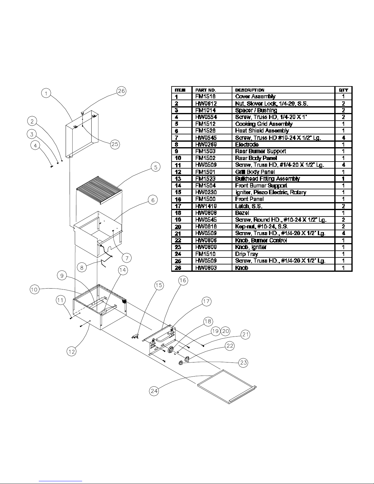
Cherokee - Expanded View

Notice to Customer
PRIOR TO OPERATING THIS APPLIANCE, READ THIS
MANUAL FULLY AND CAREFULLY. RETAIN THIS
MANUAL FOR FUTURE REFERENCE AND HAVE
AVAILABLE AT ALL TIMES. ENSURE THAT ALL
PERSONS OPERATING THIS EQUIPMENT
CAREFULLY READ AND BECOME FAMILIAR WITH
THE INFORMATION IN THIS MANUAL.
THIS UNIT HAS BEEN CAREFULLY INSPECTED AND
PACKAGED AT THE FACTORY PRIOR TO SHIPMENT.
UPON ARRIVAL, INSPECT THE APPLIANCE
CAREFULLY FOR ANY CONCEALED DAMAGE.
IMMEDIATELY REPORT ANY DAMAGE TO YOUR
AUTHORIZED DEALER.
SHOULD YOU HAVE ANY QUESTIONS REGARDING
OPERATION OR USE OF THIS APPLIANCE, CONTACT
THERMAL ENGINEERING CORPORATION AT
(803) 783-0750 OR (800) 331-0097.
THIS APPLIANCE IS DESIGN-CERTIFIED BY CSA
INTERNATIONAL, AN INTERNATIONALLY
RECOGNIZED TESTING LABORATORY, ONLY WHEN
SPECIFIED CLEARANCES ARE MAINTAINED.
IN THE U.S., OPERATION OF THIS APPLIANCE
SHOULD BE IN ACCORDANCE WITH LOCAL CODES.
IN THE ABSENCE OF LOCAL CODES, REFERENCE
THE NATIONAL FUEL GAS CODE ANSI Z223.1/NFPA
54, STORAGE AND HANDLING OF LIQUEFIED
PETROLEUM GASES, ANSI/NFPA 58 (LATEST
EDITION) OR IN CANADA, CSA B-149.1, NATURAL
GAS AND PROPANE INSTALLATION CODE.
1
NATIONALLY REGISTERED TESTING LABORATORY
U.S. Patent # 4886044
U.S. Patent # 4321857
© Thermal Engineering Corporation
Revised 11/04
-- Z21.89b-2004/CSA 1.18b-2004
DANGER
If you smell gas:
1. Shut off gas to the appliance.
2. Extinguish any open flame.
3. Open lid.
4. If odor continues, keep away from the
appliance and immediately call your gas
supplier or your fire department.
WARNING
1. Do not store spare LP cylinder within 10 feet
(3 m) of this appliance.
2. Do not store or use gasoline or other flammable
vapors or liquids within 25 feet (8 m) of this
applicance.
Warnings Notices
Failure to follow these instructions can result in
fire or explosion which could cause property
damage, personal injury or death.
Warnings to Customer
THIS APPLIANCE IS NOT INTENDED FOR COMMERCIAL
USE. THIS APPLIANCE SHALL BE USED ONLY
OUTDOORS AND SHALL NOT BE USED IN A BUILDING,
GARAGE OR ANY OTHER ENCLOSED AREA. DO NOT
INSTALL OR OPERATE THIS APPLIANCE WITHOUT
HAVING CAREFULLY READ THIS MANUAL. FOR FUTURE
REFERENCE, HAVE THIS MANUAL AVAILABLE WHILE
USING THIS APPLIANCE AND ALWAYS FOLLOW THE
INSTRUCTIONS PROVIDED.
NEVER ATTEMPT TO MAKE CONVERSIONS OR
MODIFICATIONS TO YOUR GRILL WITHOUT FIRST
OBTAINING WRITTEN INSTRUCTIONS FROM THERMAL
ENGINEERING CORPORATION.
DO NOT STORE A SPARE GAS CYLINDER UNDER OR
WITHIN 10 FEET OF THIS GRILL, ANY OTHER OPEN
FLAME, HEAT PRODUCING APPLIANCE OR HEAT
SOURCE. DO NOT ALLOW YOUR LP GAS CYLINDER TO
BE FILLED BEYOND 80% FULL.
THE USE OF ALCOHOL, PRESCRIPTION OR NON-
PRESCRIPTION DRUGS MAY IMPAIR YOUR ABILITY TO
PROPERLY ASSEMBLE OR SAFELY OPERATE THIS
APPLIANCE.
!
!

2
EXPRESS WARRANTIES
Thermal Engineering Corporation (TEC) warrants this, TEC®Cherokee
TM
Portable Gas Grill to be free
of defects in material and workmanship when subjected to normal domestic use and service from the
date of purchase as follows:
LIFETIME
The entire stainless steel outer structure is warranted indefinitely.
FIVE (5) YEARS
All components not covered by the lifetime warranty above are warranted for five years.
UNDER THIS WARRANTY
We will, at our option, repair or replace any component part deemed by TEC to be defective when
returned to a Authorized TEC Dealer or to our factory, freight prepaid, within the warranty period. Prior
to authorization of repair or replacement, you must supply the date of original purchase and serial
number of your Cherokee.
This warranty excludes damage caused by failure to follow the instructions in your Owner’s Manual or
alteration of the Cherokee’s structure or components, or from operator abuse, negligence or accident.
DISCLAIMER OF IMPLIED WARRANTIES
This warranty excludes incidental and consequential damages. Except as stated above, all other
warranties, including implied warranties of merchantability and fitness for a particular purpose, are
excluded.
If you have questions concerning this warranty, please call your local Authorized TEC Dealer or call us at
1-800-331-0097.
Lifetime Limited Warranty
T
HERMAL
E
NGINEERING
C
ORPORATION
P.O. Box 868, Columbia, South Carolina 29202-0868
2741 The Boulevard, Columbia, South Carolina 29209
Telephone: (803) 783-0750 Toll free: (800) 331-0097
Facsimile: (803) 783-0756 Toll free: (888) 581-0286
Website: www.tecinfrared.com
MODEL #: CH-10SS
SERIAL #:______________________________________
(See rating plate on back panel.)
DEALER NAME:__________________________________
DEALER TELEPHONE:____________________________
(Complete the above information for future reference.)

3
Dear TEC®Cherokee
TM
Owner:
Congratulations on selecting a TEC®Cherokee
TM
Portable Gas Grill. You’re among a select group who
truly appreciate fine cooking and demand the best. I know you’ll be pleased with the Cherokee’s
performance. Over the years, we’ve invested great resources in developing high quality gas grills that are
truly unique — from their sturdy, long-lasting construction to the unparalleled infra-red burner systems
and the wide array of optional accessories. The Cherokee was designed for those who want to be able to
take these features wherever they go! It is also ideal for those who want the finest gas grill available today
but don’t have enough space for our full-sized grills.
We've put together this manual to give you an overview of your, TEC®Cherokee
TM
and to help you get
the most from it. We've included vital information about how to set up, operate and maintain the grill
safely and correctly, so I urge you to read it carefully before first using your Cherokee. If, after reviewing
this information, you have any questions whatsoever, please call your Authorized TEC Dealer or our
Customer Service Department for assistance.
If you have comments, suggestions, or even compliments, please pass them along to us. We are
continually in search of ways we can improve our customers' experiences with our products, starting when
they first remove them from the box and continuing as they use them over the years. Hearing what you
feel we could improve, as well as what you especially like about our products and services, is essential to
this effort.
Thanks for selecting TEC!
Best regards,
THERMAL ENGINEERING CORPORATION
David H. O’Kelly
President

4
Location ....................................................4
General Overview
Location of Cherokee
Gas Connection ...........................................5
General Overview
LP Gas Cylinder Safety
Connecting Your LP Gas Cylinder
Disposable LP Gas Connection
Quick Disconnect Instructions
Gas Leak Test
Natural Gas Connection
Operation ..................................................9
General Overview
Burner Ignition
Burner Ignition Without Sparker
Extinguishing Burner Flame
Burner Low Heat Adjustment
Hazardous Locations and Conditions
Infra-red Cooking .......................................11
General Overview
Infra-red Searing Method
Helpful Hints In Cooking
Flame Flare-up Control
Sample Cooking Methods
Cleaning and Maintenance ............................13
General Overview
Protection of Burner
Cleaning and Storage
Maintenance
Appendix A. Expanded View of Burner ..............16
Appendix B. Accessories ..............................17
Appendix C. Replacement Parts .....................20
Appendix D. Troubleshooting .........................21
Contents Location
General Overview
Proper location and use is essential to insuring safe and
continued trouble-free operation. Any alterations made
to the appliance without prior written consent from
Thermal Engineering Corporation will void the product's
warranty.
In the U.S., operation of this appliance must conform to
local codes or, in the absence of local codes, the National
Fuel Gas Code, ANSI Z223.1/NFPA 54, Storage and
Handling of Liquefied Petroleum Gases, ANSI/NFPA 58; or
CSA B149.1, Natural Gas and Propane Installation Code.
Location of Cherokee
WARNING: THIS APPLIANCE SHOULD NOT BE
LOCATED CLOSER THAN 8 INCHES TO ANY
ADJACENT COMBUSTIBLE SURFACE OR UNDER ANY
OVERHEAD UNPROTECTED COMBUSTIBLE
CONSTRUCTION.
WARNING: THE APPLIANCE IS DESIGN-CERTIFIED
FOR USE OUTDOORS ONLY AND NOT INTENDED TO
BE INSTALLED IN OR ON RECREATIONAL VEHICLES
AND/OR BOATS. THIS APPLIANCE MUST BE ON A
LEVEL, STABLE SURFACE IN AN AREA CLEAR OF
COMBUSTIBLE MATERIAL. AN ASPHALT SURFACE
(BLACKTOP) MAY NOT BE ACCEPTABLE FOR THIS
PURPOSE.
When considering stationary locations for your appliance,
keep these important factors in mind. The TEC®
Cherokee
TM
must be located outdoors only. As with any
gas appliance, harmful carbon monoxide gas is produced
during the combustion process that should not be allowed
to accumulate in a confined space. Also, since hot air
rises above the Cherokee while in operation, covered
locations should be avoided. Do not locate the Cherokee
where an overhang or awning may cover it.
Minimum clearances must be maintained when operating
this appliance. Refer to Table A.1 for clearance
specifications on combustible locations. The
determination of whether a location is combustible or
non-combustible construction is made by the local fire
marshal, building inspector or the local safety authority
having jurisdiction.
The appliance ventilation louvers must remain clean and
clear of debris to avoid any obstruction to the flow of
combustion and ventilation air. Reference Table A.1 for
clearance specifications.
See the section labeled HAZARDOUS LOCATIONS
AND CONDITIONS for further information you need
to assure safe location and operation of the
Cherokee.
General Overview
WARNING: WHEN PURCHASED FOR USE WITH
PROPANE GAS, THE CHEROKEE GRILL COMES WITH
A REGULATOR ASSEMBLY THAT USES TYPE I
CYLINDER CONNECTION DEVICE FOR USE WITH A
5-20 LB. CYLINDER. THIS QUICK-CONNECT TYPE
DEVICE SHOULD ONLY BE USED WITH A TYPE I
TANK VALVE CYLINDER CONNECTION. A
REGULATOR FOR USE WITH A 16.4 OZ. DISPOSABLE
GAS CYLINDER IS ALSO PROVIDED (SEE
REGULATOR CONNECTION).
WARNING: THE GAS SUPPLY HOSE SHOULD BE
INSPECTED PRIOR TO EACH USE. DO NOT USE A
GAS HOSE THAT HAS ABRASIONS, CUTS OR
EXCESSIVE WEAR. A WORN HOSE MUST BE
REPLACED PRIOR TO USE. THE REPLACEMENT
HOSE ASSEMBLY MUST BE SPECIFIED BY TEC.
WARNING: WHEN YOUR GRILL IS STORED
INDOORS, REMOVE AND STORE THE LP GAS
CYLINDER OUTDOORS IN A PROTECTED, COOL AND
DRY LOCATION OUT OF REACH OF CHILDREN. THE
CYLINDER SHOULD NOT BE STORED IN A BUILDING,
GARAGE OR ANY OTHER ENCLOSED AREA.
WARNING: THE GAS SUPPLY MUST BE TURNED
OFF AT THE LP-GAS SUPPLY CYLINDER AND THE
LP-GAS SUPPLY CYLINDER MUST BE
DISCONNECTED FROM THE REGULATOR WHEN
THIS OUTDOOR COOKING GAS APPLIANCE IS NOT
IN USE.
LP Gas Cylinder Safety
NOTICE: AN LP GAS CYLINDER IS NOT PROVIDED
FROM THE FACTORY WITH THIS GRILL. HOWEVER,
ONLY C.F.R.49 APPROVED 5-20 LB. GAS CYLINDERS
CONSTRUCTED AND MARKED IN ACCORDANCE WITH
THE SPECIFICATIONS FOR LP GAS CYLINDERS OF
THE U.S. DEPARTMENT OF TRANSPORTATION (D.O.T)
OR NATIONAL STANDARD OF CANADA, CAN/CGA-
B339, CYLINDERS, SPHERES AND TUBES FOR THE
Location continued Gas Connection
5
COMBUSTIBLE AND NON-COMBUSTIBLE
CONSTRUCTION
Sides 8”
Back 8”
Gas, Regulator Supply Pressure Operating Pressure Main Burner Burner Input
(in. WC (kPa)) (in. WC (kPa)) Orifice Size (BTU/HR (W))
(DMS/DIA.)
LP Model 125 PSI (861), Max 11.0 (2.7) 57 (0.0430”) 14,000
HW0266 (4104)
LP Model 125 PSI (861), Max 11.0 (2.7) 57 (0.0430”) 14,000
HW0267
Table A.2. Gas Supply Specifications
Table A.1 Clearance Specifications

6
Revised 11/04
-- Z21.89b-2004/CSA 1.18b-2004
Gas Connection continued
TRANSPORTATION OF DANGEROUS GOODS;AND
COMMISSION, SHOULD BE USED. ALL APPROVED
CYLINDERS MUST BE EQUIPPED WITH AN INTEGRAL
COLLAR DESIGNED TO PROTECT THE CYLINDER
VALVE FROM DAMAGE, AS WELL AS A LISTED
OVERFILL PROTECTION DEVICE. DO NOT USE OR TRY
TO REPAIR A DAMAGED LP GAS CYLINDER AT ANY
TIME. CONTACT YOUR LOCAL LP GAS SUPPLIER FOR
REPLACEMENT. ALSO, YOU SHOULD ALWAYS
OBSERVE THE FOLLOWING PRECAUTIONS:
❚Store spare or extra gas cylinders at least 15 feet from
this grill or other open flame, heat-producing
appliance or heat source.
❚Do not fill your gas cylinder beyond 80% full.
❚Gas cylinders come with a pressure relief valve. If a
cylinder is subjected to excess heat, the relief valve will
open and let highly flammable gas vapor and/or
liquid escape. Therefore, do not store gas cylinders
near an open flame or source of heat. Store cylinders
in well ventilated areas only.
WARNING: FAILURE TO FOLLOW THE ABOVE
PRECAUTIONS COULD RESULT IN A FIRE CAUSING
DEATH, SERIOUS INJURY OR PROPERTY DAMAGE.
Connecting Your LP Gas Cylinder
WARNING: A MINIMUM OF 12 INCHES OF
CLEARANCE MUST BE MAINTAINED ON ALL SIDES
OF THE UNIT TO THE LP GAS SUPPLY CYLINDER
WHEN USING THE REGULATOR WITH HOSE
ASSEMBLY. THE LP GAS SUPPLY CYLINDER MUST
BE LOCATED IN A SAFE POSITION TO PREVENT
TRIPPING (SEE FIGURE 2).
NOTICE: FOR YOUR SAFETY, ONLY USE THE
REGULATOR AND HOSE ASSEMBLY PROVIDED AS
ORIGINAL EQUIPMENT WITH YOUR GRILL OR THE
OPTIONAL DISPOSABLE CYLINDER REGULATOR
SOLD SEPARATELY BY TEC. REPLACEMENT
ASSEMBLIES MUST ALSO BE SPECIFIED BY TEC.
NOTICE: A FIRE EXTINGUISHER FOR CLASS A, B, C
AND D FIRES SHOULD BE READILY AVAILABLE AT
ALL TIMES.
NOTICE: THE GAS MUST BE TURNED OFF AT THE
SUPPLY CYLINDER AND THE GAS CYLINDER MUST
BE DISCONNECTED FROM THE REGULATOR WHEN
THE GRILL IS NOT IN USE.
Be sure to set the gas cylinder upright so the
Cylinder Valve is at the top. This will ensure proper
vapor withdrawal.
When you connect your cylinder to the grill, you
will feel the Coupling Nipple seal when there is
slight resistance (See Figure 1). Turn about one-half
to three-quarters further to complete the
connection. Tighten only by hand; do not use tools.
If you cannot complete the final connection,
disconnect the regulator and repeat step 8 below. If
you are still unable to complete the connection,
replace the valve and regulator.
Procedure for LP Gas Cylinder Connection
(5-20 Lbs.)
1. In order to make sure the Cylinder Valve is fully
closed, turn the Handwheel clockwise until it stops.
2. Turn the burner control OFF.
3. Move your grill to an open area that is level.
4. Place the Gas Cylinder in a safe location maintaining
12 inches of clearance on all sides and locating the
cylinder and hose in a position to prevent tripping
(see Figure 2 on pg. 7). Remove the protective caps
from the Cylinder Valve outlet and Nipple as
necessary.
5. Inspect the Coupling Nut, Nipple and Cylinder Valve
for any damage, dirt or debris. Remove any dirt or
debris. Replace any damaged parts prior to use.
6. Inspect Regulator and Hose Assembly for damage, dirt
or debris. Remove any dirt or debris. Replace any
damaged parts prior to use.
7. Remove the protective cover from the appliance
connection. Attach the hose end of the Regulator to
the appliance using the “Quick Disconnect
Instructions” (see Figure 5 on pg. 8).
8. With the Regulator in your hand, insert the Nipple
into the Cylinder Valve Outlet. Make sure the
Nipple is centered in the Cylinder Valve Outlet.
Tighten the Coupling Nut by hand, making sure not
Figure 1. Coupling Assembly

to cross-thread the connection.
9. To disconnect after use, ensure that the Burner Output
Knob is in the OFF position, close the Cylinder
Valve by turning the Handwheel clockwise until it
stops.
10. Loosen the Coupling Nut by turning it
counterclockwise.
11. Disconnect the hose end of the Regulator Assembly
from the appliance using the “Quick Disconnect
Instructions”. Place the cap on the appliance
connection. Place dust cap on cylinder valve outlet
whenever the cylinder is not in use. Only install the
type of dust cap on the cylinder valve outlet that is
provided with the cylinder valve. Other types of caps
or plugs may result in leakage of propane.
Disposable LP Gas Cylinder Connection
(Type No. 600 connection)
WARNING: ONLY 16.4 OZ. DISPOSABLE CYLINDERS,
MARKED “PROPANE” OR “LP-GAS” MUST BE USED.
THE LP-GAS SUPPLY CYLINDER MUST BE
DISCONNECTED FROM THE REGULATOR WHEN
THIS OUTDOOR COOKING GAS APPLIANCE IS NOT
IN USE.
CAUTION: WHEN ATTACHED, THE TOP OF THE 16.4
OZ. DISPOSABLE CYLINDER MUST BE ATTACHED TO
THE REGULATOR AND THE BOTTOM OF THE
CYLINDER MUST REST ON THE SURFACE
SUPPORTING THE APPLIANCE. WHEN PROPERLY
INSTALLED, THE CYLINDER SHOULD REST AT AN
APPROXIMATE ANGLE OF 450FROM AN UPRIGHT
POSITION (SEE FIGURE 4) OR A FULLY UPRIGHT
POSITION (SEE FIGURE 3). THIS WILL ENSURE
PROPER VAPOR WITHDRAWAL.
Procedure for Disposable LP Gas Cylinder
Connection (16.4 oz.)
1.
Insure that the Burner Output Knob is in the
OFF position (see Figure 7 on pg. 10).
2. Inspect the Regulator for damage, dirt or
debris. Remove any dirt or debris. Replace
Regulator if damaged.
3. Remove the protective cover from the appliance
connection. Attach the Regulator to the
appliance using the “Quick Disconnect
Instructions” (see Figure 5 on pg. 8).
Gas Connection continued
7
12"
Figure 2. LP Gas Cylinder Location
Figure 3. Disposable Cylinder Attachment
Figure 4. Disposable Cylinder Location
4. Remove the protective cover from the 16.4 oz.
disposable supply cylinder (save the protective cover
in order to place it on the cylinder after use).
5. Inspect the 16.4 oz. disposable LP-gas supply cylinder
(especially the threaded connection) for damage, dirt
or debris. Remove any dirt and debris. Replace
cylinder if damaged.
6. Gently thread the 16.4 oz. disposable LP-gas supply
cylinder into the Regulator, making sure not to cross
thread the connection. DO NOT FORCE THE
CYLINDER INTO THE REGULATOR.
7. CAUTION: When installed, the top of the 16.4 oz.
disposable LP-gas supply cylinder must be attached to
the Regulator and the bottom of the cylinder must
rest on the surface supporting the appliance. When
properly installed, the cylinder must rest at an
approximate angle of 45
0
from an upright position
(see Figure 4). This will ensure proper vapor
withdrawal.
8. To disconnect, ensure that the Burner Output Knob
is in the OFF position, unthread the LP-gas cylinder
from the Regulator. Place the protective cover on the
cylinder.
9. Disconnect the Regulator Assembly using the “Quick
Disconnect Instructions” (see figure 5). Place the
protective cover on the appliance connection.
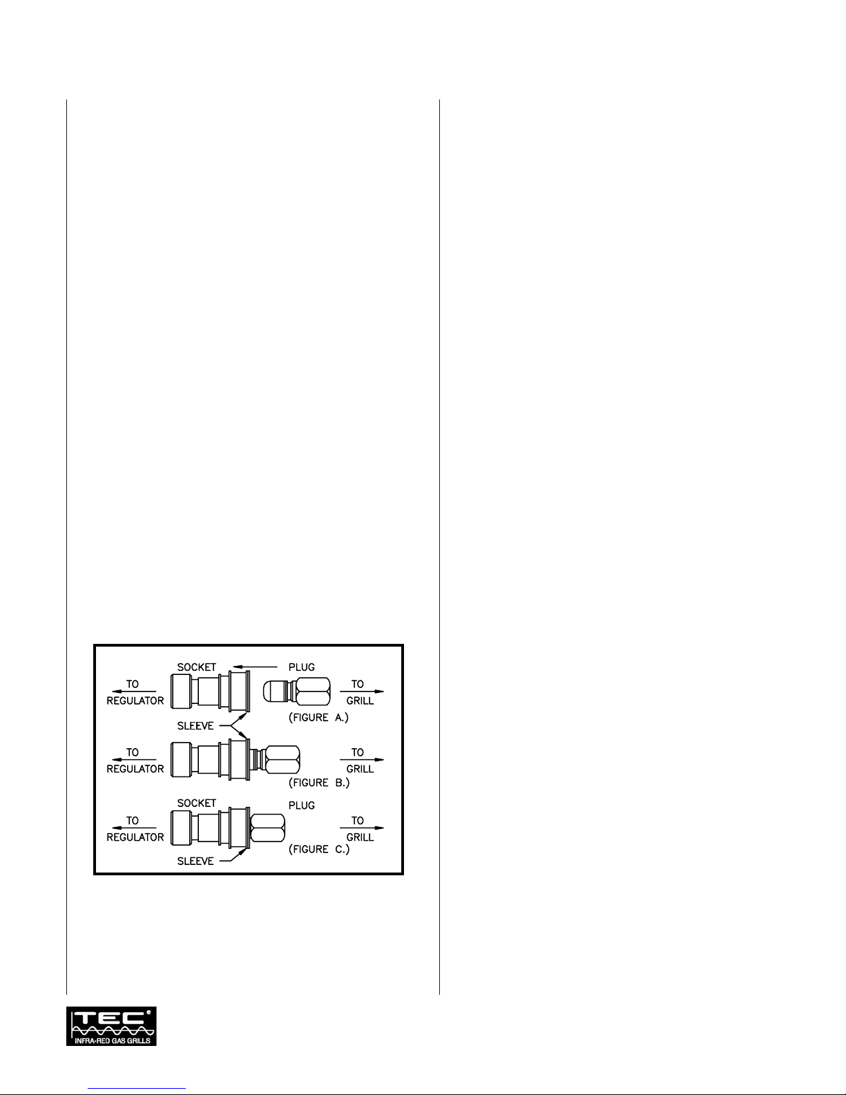
Quick Disconnect Instructions
Procedure
1.
To connect, push sleeve of socket, toward the
regulator (See Figure A.)
2. Insert plug (See Figure B.), release sleeve.
3. Push plug until sleeve snaps forward locking plug
in socket (See Figure C), (THIS
AUTOMATICALLY OPENS THE
CONNECTION ALLOWING GAS TO
FLOW).
4. To disconnect, push sleeve back and pull out
plug, (THIS AUTOMATICALLY CLOSES
THE CONNECTION TURNING OFF THE
GAS FLOW).
Gas Leak Test
WARNING: DO NOT USE OPEN FLAME TO PERFORM
LEAK TEST.
Open flame should not be used in the area around
the Cherokee during this test. This procedure
should be carried out each time the gas connection
is disconnected.
1.
Ensure that the Burner Output Knob is in the
OFF position (see Figure 6 on pg. 10).
2. Open the appliance’s gas supply cylinder valve
slowly. Apply heavy soapy water or similar
solution to all connections including those made
at the factory.
1.
Ensure that the Burner Output Knob is in the
OFF position (see Figure 6 on pg. 10).
2. Open the appliance’s gas supply cylinder valve
slowly. Apply heavy soapy water or similar
solution to all connections including those made
at the factory
3. Inspect all connections for presence of bubbles. If
bubbles appear, close shut-off valve and tighten
connections. Repeat steps 1 and 2 above until
bubbles cease.
Gas Connection continued
8
Revised 11/04
-- Z21.89b-2004/CSA 1.18b-2004
Figure 5. Quick Disconnect Fittings
9
General Overview
WARNING: NEVER ATTEMPT TO USE THIS OR ANY
OTHER GAS APPLIANCE WHEN YOU SMELL GAS. DO
NOT LEAVE THIS APPLIANCE UNATTENDED. KEEP
CHILDREN AND PETS AWAY FROM THE APPLIANCE
AT ALL TIMES.
WARNING: THIS APPLIANCE IS NOT INTENDED FOR
AND SHOULD NOT BE USED AS A HEATER. DO NOT
MOVE THIS APPLIANCE WHILE IN OPERATION.
ALLOW THE UNIT TO COOL BEFORE MOVING OR
STORING.
WARNING: THE BURNER VENTURI TUBE SHOULD
BE INSPECTED FOR SPIDER WEBS AND OTHER
OBSTRUCTIONS PRIOR TO EACH USE (SEE FIGURE
11). IF ANYTHING IS FOUND, CLEAN THE TUBE
COMPLETELY. A CLOGGED TUBE CAN LEAD TO A
FIRE BENEATH THE UNIT.
CAUTION: THE COVER MUST BE OPEN DURING
BURNER OPERATION AND THE HOOD/HEAT SHIELD
ASSEMBLY SHOULD BE IN PLACE AT ALL TIMES
DURING BURNER OPERATION.
NOTICE: NEVER PLACE FOOD OVER A BURNER
THAT IS NOT IN OPERATION. FOOD DRIPPINGS
WILL NOT BE INCINERATED AND THE SMALL PORTS
MAY BECOME CLOGGED. THE BURNER SHOULD
NOT COME IN CONTACT WITH WATER OR OTHER
CLEANING FLUIDS. IT COULD DAMAGE THE
BURNER CAUSING IT TO FUNCTION IMPROPERLY.
NOTICE: TEC RECOMMENDS THAT A FIRE
EXTINGUISHER FOR CLASS A, B, C AND D FIRES BE
READILY AVAILABLE AT ALL TIMES.
Burner Ignition
Procedure
Please read instructions before lighting.
1. Open cover.
2. Ensure gas supply cylinder Valve is closed. Ensure
Burner Output Knob is in the OFF position
(see Figure 6).
3. Open the Valve on the gas supply cylinder.
4. Depress and rotate Burner Output Knob to HIGH
setting.
5. Slowly rotate Rotary Spark Knob clockwise twice,
and check for burner flame.
6. If a flame is not present immediately, turn Burner
Output Knob to OFF position, leave the cover open,
and wait 5 minutes. Then repeat steps 3 through 6
until ignition occurs.
7. Rotate Burner Output Knob to desired cooking
level.
Burner Ignition Without Sparker
Procedure
Please read instructions before lighting.
1. Open cover.
2. If ignition does not immediately take place, turn
Burner Valve Knob to OFF and wait 5 minutes.
Then repeat the lighting procedure.
3. Insure all Valves are closed.
4. Open the Valve on the gas supply cylinder.
5. Place a match into the match wand provided. Ignite
the match. Using the match wand, place the lit
match approximately 1/4” above the burner screen.
6. Ensure the match is lit. If not, repeat step 5.
7. Depress and rotate the Burner Control Knob to ON.
Check for a burner flame. If a flame is not present,
turn the Burner Control Valve Knob to OFF, leave
the cover open, and wait 5 minutes. Then repeat the
lighting procedure.
Operation
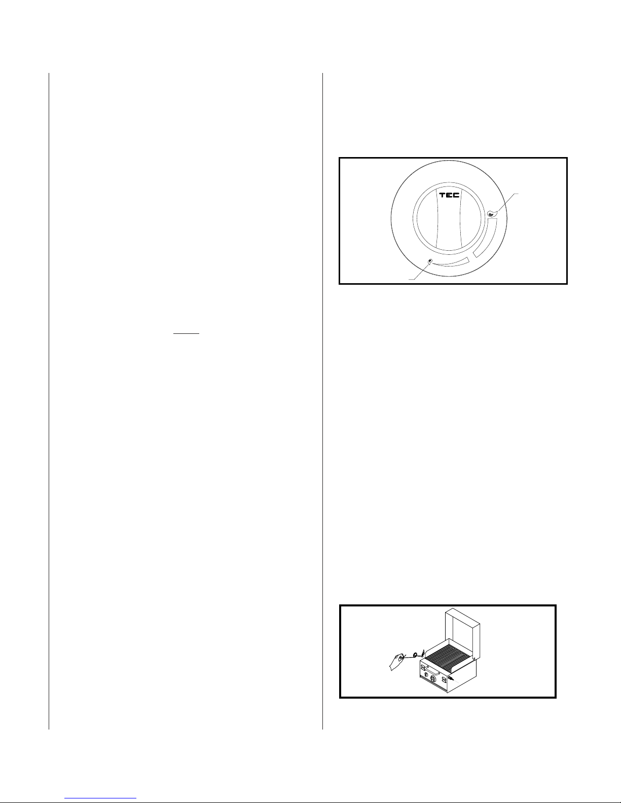
*
OFF
FERME
BURNER LOW
BURNER
HIGH
Figure 6. Burner Output Knob
Figure 7. Burner Ignition Without Sparker
Extinguishing Burner Flame
Procedure
1. Depress and rotate Burner Output Knob to OFF.
2. Close the Valve on the gas supply cylinder.
3. Disconnect the regulator assembly using the “Quick
Disconnect Instructions” on Page 9. Place the
protective cover on the appliance connection.
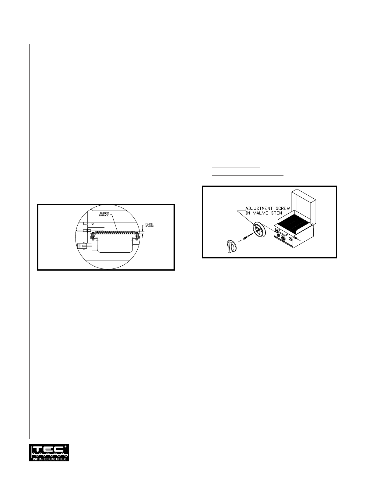
Burner Flame
The Burner Flame should be approximately 1/2” tall
when the burner is in operation. The burner flame may
not be visual in bright light. The ceramic surface and the
burner screen will heat up to red hot after 3-5 minutes
on HIGH. The ceramic surface will lose its color and a
blue flame will be visual when the burner is turned down
to LOW.
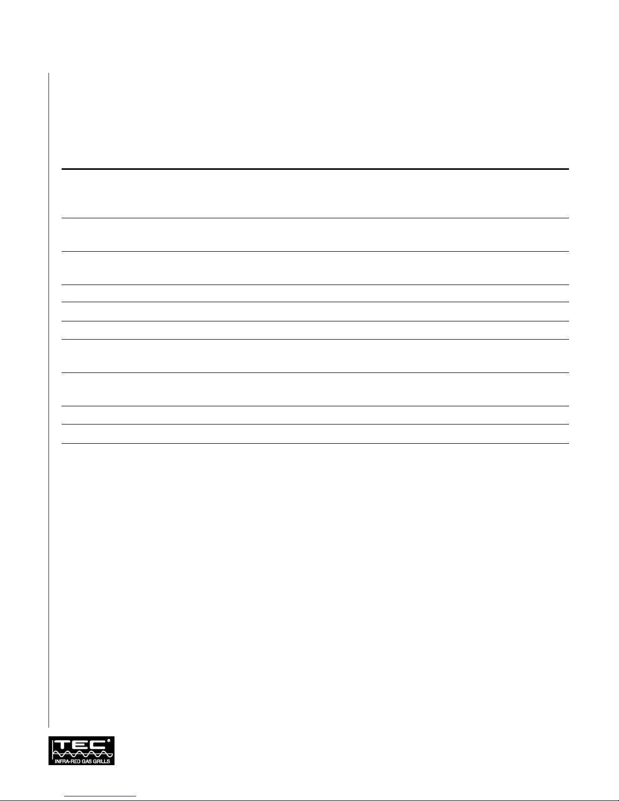
Burner Low Heat Adjustment
NOTICE: THE LOW HEAT POSITION OF THE FLAME
MUST BE STABLE AND SHOULD NOT WAIVER ON
THE BURNER SURFACE. NEVER ADJUST THE
BURNER SO LOW THAT IT MAY GO OUT DURING
USE.
The burner’s Low Heat Output is preset at the factory. If
it should be necessary to adjust this setting due to a
particular cooking style or different environmental
conditions, follow the instructions below.
The Low Heat Adjustment Screw only affects burner
operation at the Burner LOW setting. Any efforts to
make adjustments at another setting will have no effect
until the burner is turned to Burner LOW, where the
burner may involuntarily extinguish while gas is still
flowing. This condition is unsafe, therefore adjustments
should ONLY be made with the Burner Output Knob at
the Burner LOW setting while visually monitoring
changes (See Figure 9).
Procedure
1. Follow Burner Ignition procedures and operate
Cherokee for approximately 5 minutes.
2. Turn the Burner Output Knob to the Burner LOW
position and wait until the flame stabilizes.
3. Remove Burner Output Knob from valve stem.
4. Insert small blade type screwdriver into valve stem to
engage recessed Low Heat Adjustment Screw. Turn
clockwise to reduce low heat intensity, or turn
counter-clockwise to increase. This adjustment
affects the flame at the LOW setting ONLY.
Hazardous Locations and Conditions
■Do not use your Cherokee closer than 8” to any
combustible surface (wood wall or wooden fences,
etc.). Do not use your Cherokee under any
overhead unprotected combustible construction
(i.e., wood, canvas, plastic, etc.).
■Do not obstruct the flow of combustion and
ventilation air.
■This appliance should only be used outdoors in a
well-ventilated space and must not be used in a
building, garage, or any other enclosed area.
■Keep all flammable substances away from this
appliance. These include aerosols and aerosol
containers, gasoline and similar liquids, paper and
paper products, and containers of grease, paint, etc.
■Avoid wearing flammable and/or loose clothing such
as neckties, scarves, etc., while using the Cherokee.
Operation continued
10
Revised 11/04
-- Z21.89b-2004/CSA 1.18b-2004
Figure 9. Low Heat Adjustment
Figure 8. Burner Flame

11
General Overview
Now that you are ready to begin cooking, you can enjoy
cooking outdoors quickly and effortlessly. In minutes,
you can enjoy steaks, hamburgers, poultry, pork chops,
roasts, fish and other foods. You can also cook more
slowly if you wish. TEC’s optional accessories are
designed to enhance your grill’s versatility.
Infra-red Searing Method
Searing is a process that seals juices in food by cooking
with intense heat for a short period of time. The juices
stay in the food where they belong and the outside gets
coated with flavorful grilling aroma. For best results,
follow these procedures when cooking.
The intense Infra-red energy generated by your TEC grill
has many advantages. For example, meat is evenly cooked
throughout. Also, grease and food particles incinerate on
contact with the burner and convert into flavorful vapors
that cook back up into your food.
Searing Method
1. Follow the Burner Ignition procedures and operate
the grill for 5 minutes or until the ceramic burners
glow orange.
2. Set the Burner Output Knob to HIGH and place
the food on Cooking Grid for 1-2 minutes, or until
food lifts without sticking.
3. Turn the food and repeat step 2.
4. Depending upon your taste, continue cooking on
HIGH, turning the food frequently, or adjust the
Burner Output Knob between LOW and
MEDIUM and continue cooking until the food is
cooked to your satisfaction. Turn as necessary
(generally every 1 to 3 minutes).
During the searing process, flashing may occur when
juices vaporize on contact with the Cooking Grid and
Burner surface. The flashes and smoke greatly enhance
the flavor by “char-cooking” your food.
Helpful Hints In Cooking
1. Cover the Drip Tray with foil. This helps with
clean-up. Be careful not to cover the ventilation
openings at front of the Drip Tray.
2. Use the proper cooking tools, long handled tongs,
spatula, knife, mitts and a hot pad for handling hot
items. When turning or moving foods, use tongs or
a spatula, instead of a fork. Piercing the food with a
fork lets the natural juices and flavor escape.
3. Monitor meat temperature. Bring large cuts of meat,
roast, or fowl to room temperature before cooking.
Smaller meat cuts such as hamburgers, wieners, or
small steaks may be cooked directly from the
refrigerator. Note: TEC does not recommend
cooking portion meats from a frozen state.
4. Start slowly. Infra-red grilling is unlike other outdoor
cooking methods. It may take you time to perfect
the fast cooking process. As a benchmark, foods that
generally cook in 20 minutes or less on conventional
grill, cook in about one-half the conventional time
on a TEC Infra-red grill. Please refer to the section
entitled
SAMPLE COOKING METHODS
on page 13.
Flame Flare-up Control
NOTICE: NEVER DOUSE A FLARE-UP WITH WATER. IT
WILL DAMAGE THE BURNER!
To minimize flame flare-ups:
■Use Cooking Grid with U-shape Channels facing
up.
■Trim excess fat from meat.
■Preheat the grill for 5 minutes before each use.
■Reduce heat and reposition food while cooking.
■Move the food to the rear until the flare-up has
diminished.
■Prevent excess grease build up by periodically
cleaning the Cooking Grid.
Infra-red Cooking
12
Revised 11/04
-- Z21.89b-2004/CSA 1.18b-2004
Sample Cooking Methods
Use this chart as a cooking guide. Cooking times may vary, depending on thickness of food.
FOOD CONTROL SETTING TOTAL COOKING TIME
Steak 1" Thick High fire 2 min. each side 4 min. - Rare
High fire 2 min. each side. Balance medium fire 6 min. - Medium
High fire 2 min. each side. Balance medium fire 8 min. - Well Done
Hamburger 1/2" Thick High fire 21/2min. each side 5 min. - Medium
High fire 3 min. each side 6 min. - Well Done
Chicken - Parts High fire 2 min. each side 20 - 25 min.
Balance medium-low to low fire
Chicken Breast 3/4" Thick, Filleted High fire 2 min. each side 8 - 10 min.
Hot Dogs Medium-Low 4-6 min.
Pork Chops Medium 6 min. per side
Spare Ribs High fire 5 min. 20 min. per side
Low to finish Turn often
Lamb Chops High fire 5 min. 15 min. per side
Medium to finish
Fish 1 lb. Medium-Low 6-8 min. per side
Shrimp, Shelled Medium-Low 3-4 min. per side
Kabobs Medium-Low 4-5 min. per side (2 sides)
Infra-red Cooking continued

13
General Overview
Proper care, maintenance and cleaning will help ensure
long life of your grill. Periodic cleaning will help avoid
accumulations of flammable grease, fats, and other
debris.
Because of the high intensity of the Infra-red Burner, any
drippings and food particles that fall onto the Burner
surface are immediately incinerated. However, some
debris and residue may remain. To remove this residue
after cooking, turn the grill on HIGH for 5-10 minutes
with the cover OPEN. This is referred to as the “BURN
OFF” phase.
Protection of Burner
The Burner of your grill is designed to provide a long life
of satisfactory performance. However, there are steps you
must take to prevent cracking of the Burner’s ceramic
surface, which will cause the Burner to malfunction.
Following are the most common causes of cracks and the
steps you must take to avoid them. Damage caused by
failure to follow these steps is not covered by your grill
warranty.
IMPACT WITH HARD OBJECTS -
Never allow hard objects
to strike the ceramic. You should take particular care
when inserting or removing Cooking Grid and
accessories into or from the grill. If objects such as these
fall onto the ceramic, it is likely to crack the ceramic.
IMPAIRED VENTILATION OF HOT AIR FROM GRILL -
In order
for the Burner to function properly, hot air created by the
Burner must have a way to escape the grill. If the hot air
is not allowed to escape, the Burner may become
deprived of oxygen, causing them to backfire, especially if
the Burner output is set at HIGH. If this occurs
repeatedly, the ceramic may crack. This is the reason your
grill was designed with ventilation louvers, and the
accessories were designed to leave open space at the grill
surface. These design features give the hot air an escape
route. Accordingly, never operate your grill with very
little or no open space at the cooking surface (the
Cooking Grid provide sufficient open space).
Also, never cover the ventilation louvers with foil or other
materials that prevent air flow. Specifically:
■Do not cover the entire surface with foil, a large pan,
etc.
WATER OR OTHER LIQUIDS -
When the burner are in
operation, their intense heat is normally sufficient to
vaporize any drippings, marinades or sauces that contact
the surface as a by-product of grilling. This does not
include water thrown into the grill to douse a flame.
Cold liquid contacting a hot surface in substantial
amounts can cause the surface to break. Also, if the
ceramic or interior of a Burner becomes wet while not in
use, later operation of the Burner can create steam, which
may produce enough pressure to crack the ceramic. In
addition, repeated soaking of the ceramic will cause it to
swell and expand. This expansion will create pressure on
the ceramic and cause it to crack and crumble.
■Never douse water into the grill to control a flare-up.
■Never expose the Burners to the risk of soaking by
rainfall, sprinklers or otherwise. Further, do not
attempt to operate your grill in the open air while it
is raining. Finally, after you use the grill, close the
cover as soon as you turn the burners OFF so that, if
it rains, the Burner will not be exposed to direct
rainfall.
■If you find standing water in your grill (because of
exposure to rainfall, etc.), examine the ceramic
burner surface for evidence of possible water soaking.
If the ceramic appears to be wet, remove the Burner
from the grill and turn them upside down to empty
any water from the Burner body. After draining all
the water, place the Burner indoors and allow it to
dry thoroughly. Also, empty any water standing in
the grill’s Drip Tray. Then, reinstall the Burner. After
testing for gas leaks around all fittings as described in
the section entitled
GAS LEAK TEST
on page 9, you
should be able to resume normal use of your grill.
For further Burner maintenance instructions, see
MAINTENANCE
section
.
Cleaning and Maintenance
14
Revised 11/04
-- Z21.89b-2004/CSA 1.18b-2004
Cleaning and Storage
CAUTION: ALWAYS ALLOW THE GRILL TO COOL
BEFORE CLEANING. DO NOT ALLOW WATER TO MAKE
CONTACT WITH THE BURNER SURFACE, AT ANY TIME.
Drip Tray
Remove soiled foil and rinse the Drip Tray with soap and
water. Re-cover the Drip Tray with foil.
Heat Shield
Remove soiled foil and re-cover. If necessary, the Heat
Shield may be removed for further cleaning with soap
and water.
Cooking Grid
Leave the Cooking Grid in place for 5-10 minutes while
the Burner is on HIGH and the hood OPEN. The
Cooking Grid may also be removed and cleaned with a
brass or stainless steel bristle brush and soapy water.
Standard oven cleaners may be used for deeper cleaning.
Rinse the Cooking Grid thoroughly with clean water
before using.
Storage and Transport
Caution: Always allow the grill to cool before handling
or storing. Place the Cooking Grid in the Drip Tray
when transporting. Always store the grill in its upright
cooking position. Storage of this appliance indoors is
permissible only if the cylinder is disconnected and
removed from teh appliance. Cylinders must be stored
outdoors, out of the reach of children, and must not be
stored in a building, garage or any other enclosed area.
Maintenance
The Cherokee requires very little maintenance. However,
a periodic inspection of orifice openings and venturi
inlets to clear obstructions to gas flow is recommended.
Burner Head
The most important way to maintain the performance of
the Infra-red Burner is to operate the grill on HIGH for
at least 5 minutes after each use.
This procedure will leave some ash on the surface of the
Burner Head. If it accumulates in excessive amount, it
will clog the small ports in the ceramic surface. To
prevent this blockage, remove the Cooking Grid and
vacuum the burner surface with a low-suction vacuum
cleaner or sweep away ashes with a soft bristle brush,
every six months, or as necessary. When performing this
procedure be careful not to scrape or strike the ceramic
with the suction device, which may damage the ceramic.
The ceramic surface of the Burner is fragile and must be
handled carefully.
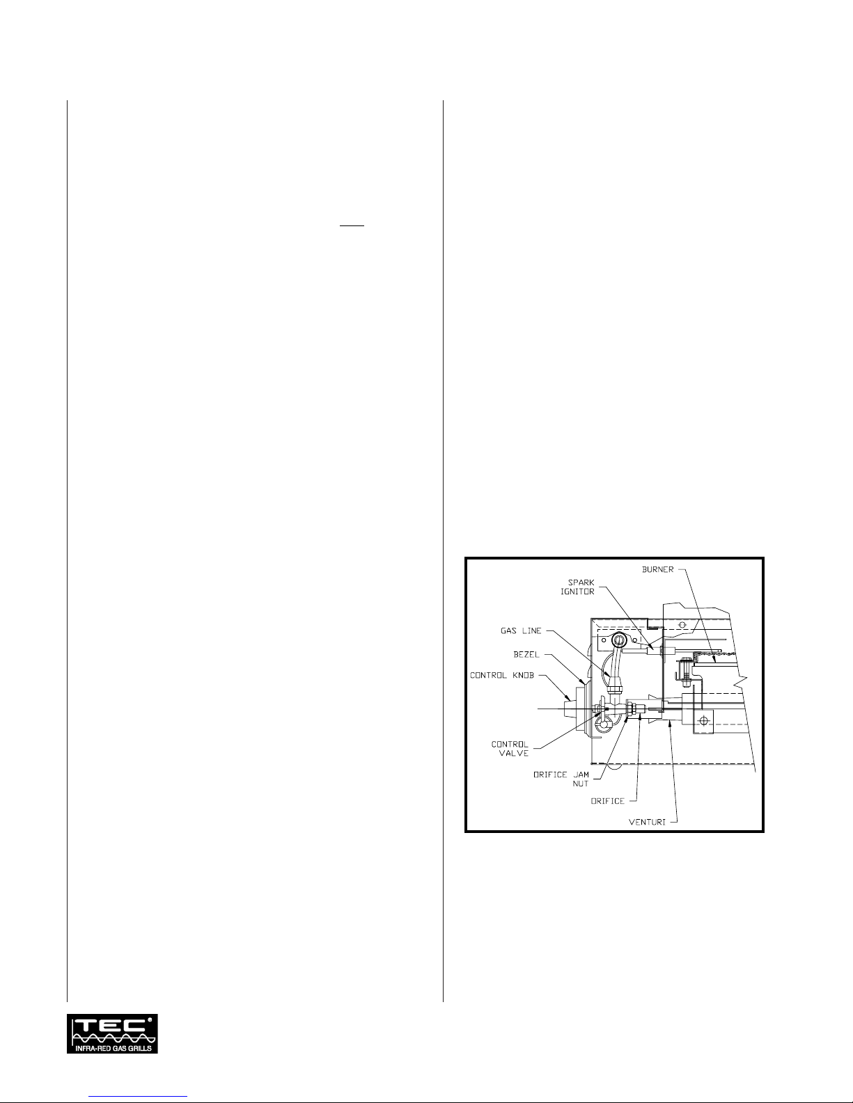
WARNING: EACH GAS ORIFICE MUST BE PROPERLY
LOCATED ON THE ORIFICE BRACKET, ATTACHED TO
THE VENTURI ON THE BURNER ASSEMBLY. AN
IMPROPERLY LOCATED ORIFICE CAN LEAD TO
BODILY INJURY AND PROPERTY DAMAGE. THE
PROPER LOCATION IS SHOWN IN FIGURE 10.
Figure 10. Combustion Components
Cleaning and Maintenance continued

15
Appendix A: Cherokee Expanded View of Burner
Figure 11. Cherokee Expanded View
Reference Guide
ITEM PART NO. DESCRIPTION QUANTITY
1 FM1525 Burner Body Weldment 1
2 FM1537 Tubing Assembly, Gas supply. 1
3 HW0264 Valve, Burner 1
4 FM1520 Ceramic Burner Clamp 2
5 FM1521 Screen Retainer Clamp 2
6 HW0555 Screw, Hex HD, 1/4-20 X 1-1/2” Lg., S.S. 1
7 HW2505 Screw, Slotted Hex HD, 10-24 X 1-1/2” Lg., S.S. 2
8 FM1519 Burner Head Clamp 2
9 HW0609 Nut, Lock, 3/8-27, Bras 1
10 HW020257 Orifice #57 1
11 FM1130 Burner Head Rail 1
12 FM1527 Burner Screen 1
13 FM1124 Burner Head Assembly 1
14 HW0311, HW0312 Fiberfrax, 1/8” Thick 2
15 HW2505 Screw, Slotted Hex HD, 10-24 X 1-1/2” Lg., S.S 1
16
Revised 11/04
-- Z21.89b-2004/CSA 1.18b-2004
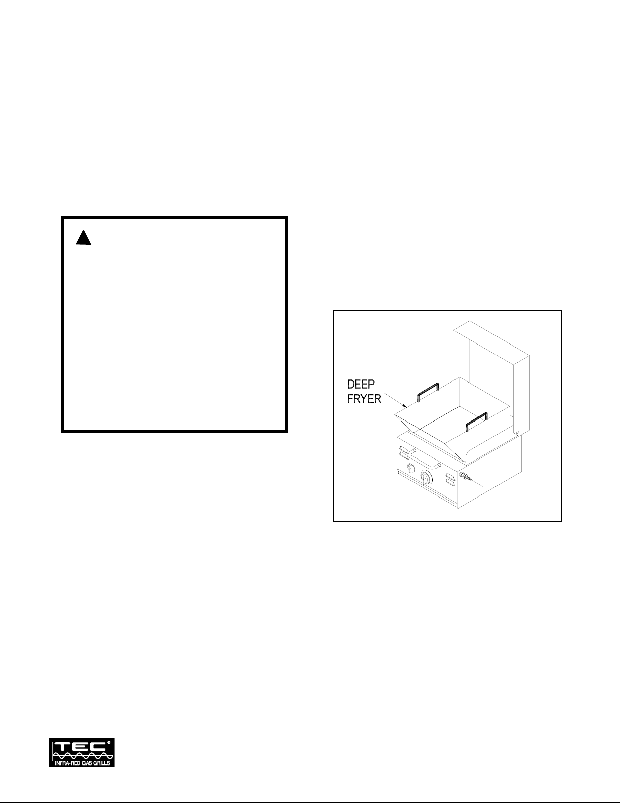
Deep Fryer/Steamer
The Deep Fryer lets you cook foods that have been
traditionally limited to indoor cooking. It’s great for
frying chicken, french fries, shrimp or fish; or boiling
corn or potatoes and for cooking stews. (Please note that
the Deep Fryer / Steamer is a combined accessory giving
you frying, as well as steaming capabilities.)
Deep Fryer Use
CAUTION: DO NOT CLOSE COVER WHILE USING THIS
ATTACHMENT FOR FRYING. HOT COOKING OIL CAN
CAUSE BURNS. ALWAYS WEAR OVEN MITTS WHEN
USING THE DEEP FRYER AND USE EXTREME CAUTION
WHEN HANDLING HOT COOKING OIL OR WATER.
OIL WILL BURN IF OVERHEATED. DO NOT LEAVE
UNATTENDED WHILE HEATING. IF SMOKING OCCURS,
REDUCE HEAT. IN THE EVENT OF AN OIL/GREASE FIRE,
DO NOT ATTEMPT TO EXTINGUISH WITH WATER. USE
TYPE BC DRY CHEMICAL FIRE EXTINGUISHER OR
SMOTHER FIRE WITH DIRT, SAND OR BAKING SODA, OR
COVER FRYER WITH STEAMER LID UNTIL COOLED.
1. Remove the Cooking Grid.
2. After removing the Steamer attachment, place the
Deep Fryer over the Burner.
3. Fill the Deep Fryer one-third full with cooking oil or
water (one-gallon). DO NOT OVERFILL.
4. Follow the Burner Ignition procedures for the
Burner and operate the grill for 5 minutes or until
the ceramic Burner glows orange.
5. Let the Burner stay on HIGH for 4 to 8 minutes to
properly heat cooking oil or water. We suggest you
use a candy thermometer to check the temperature
of the oil or water. Normally, 350°F is sufficient for
frying.
6. Turn Burner control dial between MEDIUM and
LOW. Do not leave the burner on HIGH.
7. Place the food into Deep Fryer with long-handled
utensils.
8. After cooking, turn the burner to OFF. Let the grill
and cooking oil or water cool to room temperature
before attempting to remove the Deep
Fryer/Steamer.
Appendix B: Accessories
WARNING:
1. In the event of rain while cooking with oil
/ grease, cover the cooking vessel
immediately and turn off the appliance
burner and gas supply. Do not attempt to
move the appliance or cooking vessel.
2. When cooking with oil / grease, do not
allow the oil / grease to exceed 350°F
(177°C). Do not store or use extra
cooking oil in the vicinity of this or any
other appliance.
3. Do not leave oil / grease unattended.
Figure 12. Deep Fryer
The TEC Deep Fryer has not been tested by CSA International.
!

17
Steamer
The Steamer is great for steaming vegetables like broccoli,
new potatoes, carrots or cauliflower. It’s also ideal for
seafood such as shrimp, clams and oysters. The Steamer is
used together with the Deep Fryer.
CAUTION: STEAM CAN CAUSE SERIOUS BURNS.
ALWAYS WEAR OVEN MITTS. USE EXTREME CAUTION
WHEN REMOVING STEAMER LID.
Steamer Use
1. Remove the Cooking Grid.
2. Place the Deep Fryer/Steamer over the Burner.
3. Fill the bottom of Fryer with
1
/
2
" to
3
/
4
" of water.
Repeat this throughout the cooking process so that
the liquid level is maintained. Be careful not to spill
liquid onto the Burner.
4. Place the Steamer Screen in the bottom of Deep
Fryer. Cover with the lid.
5. Follow the Burner Ignition procedures for the
Burner and operate the grill for 5 minutes or until
the ceramic Burner glows orange.
6. Let the right Burner stay on HIGH for 4 to 8
minutes to allow water to boil.
7. Turn the Burner control dial between MEDIUM
and LOW. Do not leave the burner on HIGH.
8. Remove the lid and add the food.
9. Cook until desired texture is attained.
10. After cooking, turn the burner to OFF. Let the grill
and water cool to room temperature before removing
Deep Fryer/Steamer.
Figure 13. Steamer
The TEC Steamer has not been tested by the CSA International.
Appendix B: Accessories continued

18
Revised 11/04
-- Z21.89b-2004/CSA 1.18b-2004
Griddle
The Griddle provides a surface for you to use your grill
for pan frying foods such as bacon, eggs, sausage, french
toast and pancakes, and also for blackening fish and
meats. After each use, the Griddle should be
thoroughly washed with warm soap and water, dried
and rubbed with cooking oil to season the griddle, prior
to storing.
Griddle Use
1. Remove the Cooking Grid.
2. Place the Griddle over the Burner.
3. Follow the Burner Ignition procedures for the
Burner and operate the grill for 5 minutes or until
the ceramic burner glow orange.
4. Adjust Burner Output to between MEDIUM and
LOW for frying, or between MEDIUM and HIGH
for blackening.
5. Turn the Burner to OFF when you are finished
cooking. Let the grill and Griddle cool to room
temperature before removing the Griddle.
Figure 14. Griddle
The TEC Frying Griddle has not been tested by CSA International.
Appendix B: Accessories continued
Table of contents
Other TEC Infra-red Grill manuals


Popular Grill manuals by other brands


HAUSSLER
HAUSSLER Barbecue operating instructions

Champion
Champion CHEG210 user manual

Carolina Cooker
Carolina Cooker M107828 owner's guide

Brinkmann
Brinkmann DS-30 owner's manual

Brinkmann
Brinkmann SMOKE'N GRILL Owners manual assembly and operation instructions

Lynx
Lynx ALL-TRIDENT L30ATRF Care & use/installation