TEC AP160N Series 1000VA User manual

USER MANUAL
On-Line UPS
Model AP160N
1000VA/2000VA/3000VA
Uninterruptible Power SupplySystem
CONTENT
1.Safetyand EMCInstructions..............................................................4
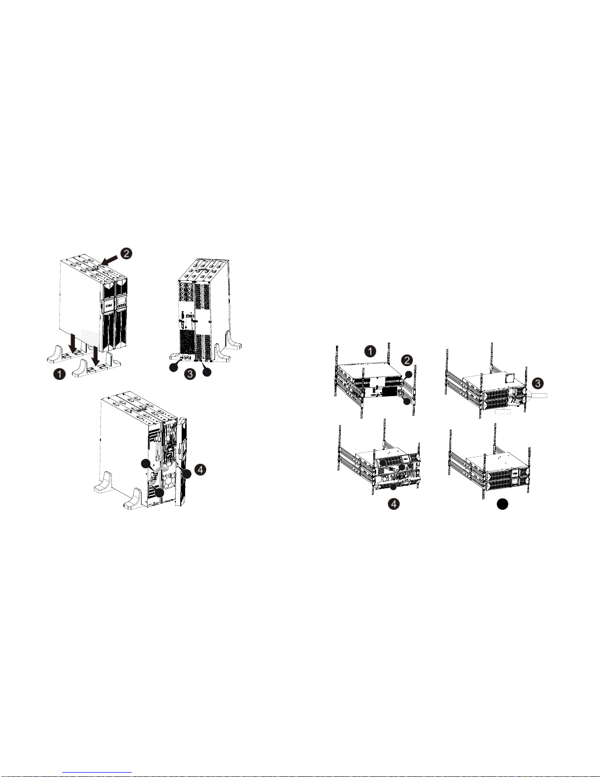
1.1 Installation.............................................................................................4
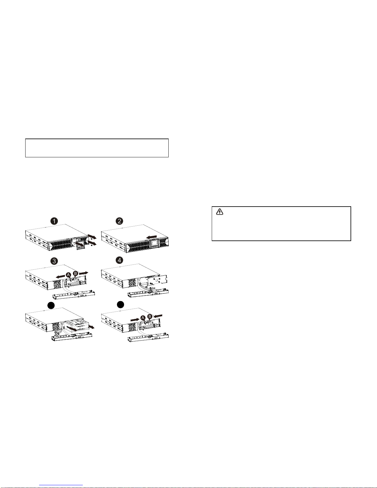
1.1.4 EBMInstallation (Optional)................................................................5
1.2 Operation..............................................................................................9
1.3 Maintenance, servicing and faults......................................................10
1.4 Transport.............................................................................................13
1.5 Storage...............................................................................................13
1.6 Standards............................................................................................14
2.Description of CommonlyUsedSymbols.......................................15
3.Introduction.........................................................................................16
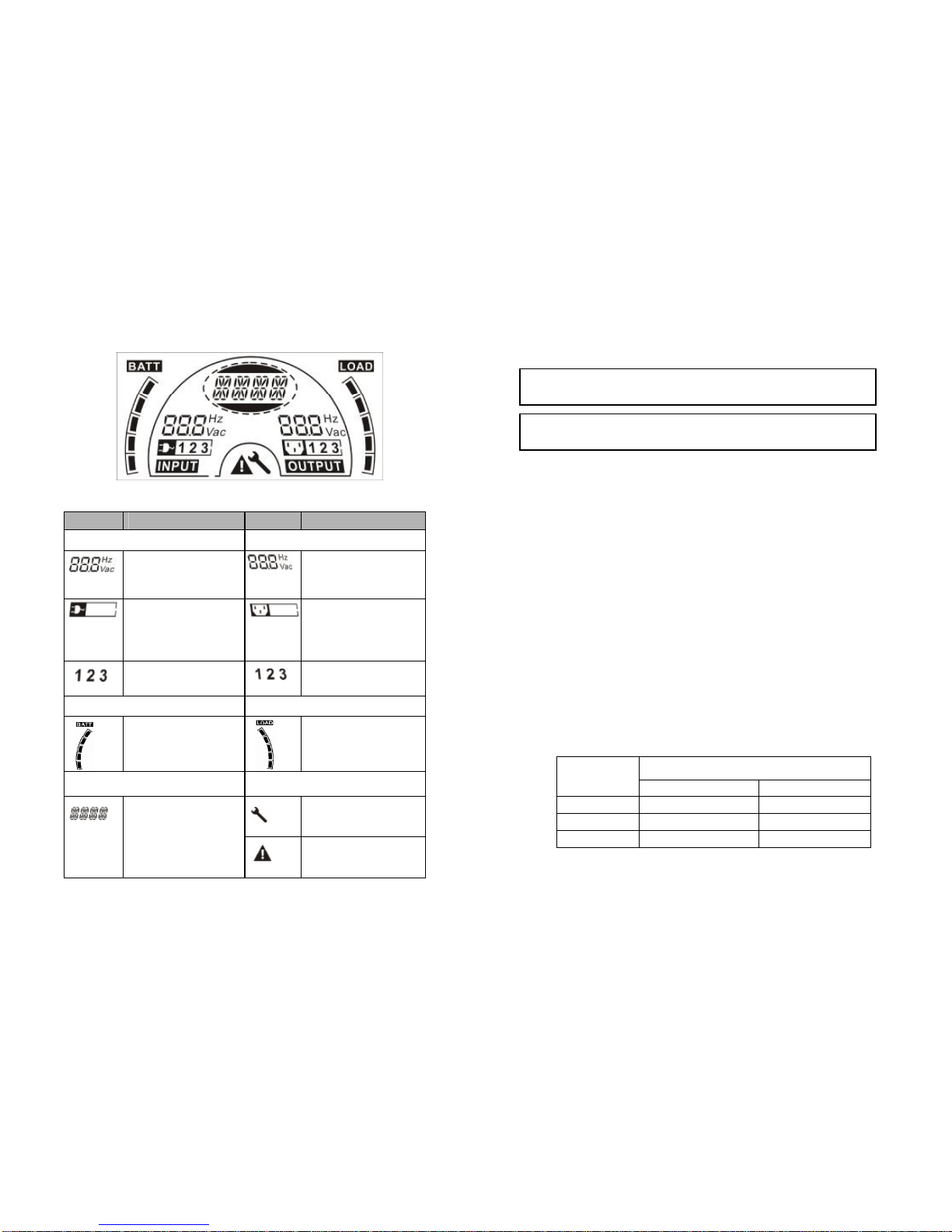
4.Panel Description...............................................................................17
5.Connection and Operation................................................................19
5.1 Inspection:..........................................................................................19
5.2 Connection:.........................................................................................19
5.3 Batterycharge:...................................................................................21
5.4 Turnon theUPS:................................................................................21
5.5 Test function:.......................................................................................21
5.6 Turnoff the UPS:................................................................................22
5.7Audible alarmmutefunction:..............................................................22
5.8 Operation procedure ofexternal batteryforlong backup timemodel
(“S” model)................................................................................................22
6.Operating Mode for All Models.........................................................24
6.1 Line mode...........................................................................................24
6.2 Battery mode......................................................................................25
6.3 Bypass mode......................................................................................25
6.4 NO outputmode.................................................................................26
6.5 EPO(EmergencyPower Off).............................................................26
6.6 ECOmode (Economymode).............................................................26
6.7 Convertermode..................................................................................27
6.8Abnormal mode..................................................................................27
7.Setting byLCDModule......................................................................28
8.Trouble Shooting................................................................................30
9. Maintenance........................................................................................32

9.1 Operation............................................................................................32
9.2 Storage...............................................................................................32
9.3 BatteryReplace..................................................................................32
10.TechnicalData...................................................................................33
10.1 Electrical specifications....................................................................33
10.2 Operating Environment.....................................................................33
10.3Typical backup time(Typical values at25°C inminutes:)....................33
10.4 Dimensions and weights....................................................................34
11. Communication Port........................................................................34
11.1 RS-232 andUSB communicationports............................................34
11.2 RS-232 port.......................................................................................35
11.3 USBport...........................................................................................35
11.4 Installing aSerial Network Management Card (optional).................35
12.Software.............................................................................................37
Appendix:Rear panel.............................................................................38
4
1. Safetyand EMC Instructions
1.1Installation
See installation instructionsbefore connecting to thesupply.
Condensation mayoccur ifthe UPSis moved directly from acoldto a
warm environment. TheUPS mustbe absolutelydrybefore being
installed. Please allow an acclimatization time ofat least two hours.
Do not install the UPSnearwater orin damp environment.
Do not install the UPSwhere it would be exposed todirect sunlight or
near heat.
Do not connectappliances or itemsof equipment which would overload
the UPS(e.g. laser printers, etc) to the UPS output.
Place cables in such a waythat no one can step on ortrip over them.
Assureto connect with theearth reliably.
Assureexternal batterysource must be earthed.
Connectthe UPS onlyto an earthed shockproof socket outlet.
The buildingwiring socket outlet (shockproof socket outlet)must be
easilyaccessible to close to the UPS.
With the installation of the equipment, the sum of the leakage current of
the UPSand the connected load does not exceed 1,5mA.
Do not blockventilation openingsin the UPS’shousing. Ensure theair
vents on the front and rearof the UPS arenot blocked. Allowat least
25cm of space on each side.
UPShasprovided earthed terminal, in the final installed system
configuration, equipotential earth bonding tothe external UPSbattery
cabinets.
An appropriate disconnect deviceas short-circuit backup protection
should be provided in thebuilding wiring installation. Pleasesee the
disconnect device specificationin chapter 5.2.
The equipment is powered bymore than one source.
1.1.1 Inspection of Unit
Inspect theUPS upon receiving. Ifthe UPS is apparentlydamaged during
the shipment, please keepthe boxand packing materialin original formfor
the carrier and notifythe carrier and dealer immediately.
Pleasereadcarefullythefollowing usermanualand the safety
instructions before installing the unit or using the unit!

5
1.1.2 Unpacking theCabinet
Tounpackthe system:
1. Open the outer carton and remove the accessories packagedwith the
cabinet.
2. Carefully lift the cabinet out of the outer carton and set it on a flat, stable
surface.
3. Discard orrecycle the packaging in a responsible manner,or store it for
future use.
1.1.3 UPS Setup
All model series aredesigned for tower and rackpurpose. Theycan be
installed into a19 inchesequipment rack.Please follow the instruction for
Tower Setup and Rack-Mount Setup.
lTowersetup
This seriesofUPS can beplaced horizontallyandvertically.Asatower
configuration,it is providedwith theoptionalUPS standsto stabilizetheUPS
when the UPS is positionedinvertical. The UPS standmust be attachedto the
bottomof the tower. Use the followingproceduretoinstall UPS in UPS stands.
1. Slidedown theUPS verticallyandputtwo UPSstandsat the end of the
tower.
2. Place down the UPS into twostandscarefully.
3. Pull out the LCD box androtate itinaclockwise directionto 90degreeand
thenpush it backin the front panel.
5
lRack-mountsetup
Theseriescanbeinstalledin 19 inchesracks. Both theUPS and external
batteryenclosureneed2Uofvaluable rackspace.
Usethefollowing procedure to install UPSin a rack.
1. Align themounting earswithscrewholesontheside oftheUPS, and
tightenthescrew.
2. Assemble the rackrails with the rack-mounting.
3. Slide in the UPS into therack rail and lockit in the rackenclosure.
4. Tighten the screw, and theloadcanthen beconnect
1.1.4 EBMInstallation (Optional)
lConnecting the EBMin Tower form:
1. Slide down the UPSand EBMverticallyand place two UPS stands with the
extend part at the end of the tower.
2. Tighten the screw on the metal sheetforstabilization
3. Connect the Earth line fromUPS(port A ) to EBM (port B)
4. Takeoffthe front panel, and connect the batteryterminal (A)from UPSto
EBM terminal (B)shown as below.Users need to removethe small gate(C)

6
on side of the frontpanel toallow the outlet wire of the EBMto passthrough
the gate and then reassemble front panel.
B
A
C
B
A
7
lConnecting the EBMin arackform
1. Using the same method asassembling UPSin arack form, assemble EBM
into therack-mounting onthe top or bottom of the UPS.
2. Connect the earth line fromUPS (portA )to EBM (portB)
3. Take off the LCD box, and unscrewthe internalscrews.
4. Takeoff the front panel, and connect the batteryterminal (A)from UPS to
EBM terminal (B)shown asbelow.Users need to remove the small gate(C)
on side of the front panel to allow the outlet wireof the EBMto passthrough
the gate and then reassemble front panel.
5. After installing the UPSintorack,the load can then be connected to UPS.
Please make sure the load equipment isturned offbefore plugging allloads
into theoutput receptacle
lConnecting the Multiple EBMs
1KVA/2KVA and 3KVA UPSinclude external batteryport that allowsusersto
connect multiple EBM in order to provide additional backup time. Follow the
procedure to install multiple EBM asbelow.
A
B
BA
C
Unscrew
Unscrew
5

8
Connecting multiple EBMsin Tower form
1. Connect Earth line between UPS and the firstEBM,and then connect Earth
Line between the first EBM and the second EBM.
2. Takeoff the front panel,and connect thebatteryterminal (A)from UPSto
EBM terminal (B)shown as below. And then connect the batteryterminal(D)
from the firstEBM tothe batteryterminal (E)from the second EBM. Users
needto remove thesmall gate(C) on side ofthefront panelto allowthe
outlet wire ofthe EBM to pass through thegate and then reassemble front
panel.
Connecting theMultiple EBMs in rack form
1. ConnectEarth line between UPS and the firstEBM,and then connect
Earth Line between the firstEBM and the second EBM.
2. Takeoff the frontpanel, and connectthe batteryterminal (A)from UPS to
EBMterminal (B) shownas below. And then connectthe batteryterminal
(D)from the firstEBMto the batteryterminal (E)from thesecond EBM.
Users need to removethe small gate(C)on side of the front panel to allow
the outletwireof theEBM to passthrough the gate and then reassemble
front panel.
B
C
A
D
E
9
Note: Three or moreEBMscan be connectedto theUPSin the samewayas
shown above.
Note: Afterconnect the EBMs, please do not forget to set the number of EBMs
on LCD, please refer to chapter 7“Setting byLCD module” forsetting method.
If use the nonstandard EBMs, pleasecall localdealeror distributorforsetting
method.
1.2 Operation
Do not disconnectthe mains cable on theUPSorthe building wiring
socket (grounded shockproof socket) during operation asthiswould
remove the ground to the UPS and of all connected loads.
TheUPS featuresits own, internal current source (batteries).You maybe
electric shockwhen you touchthe UPSoutput socketsor output terminal
blockeven if the UPS is not connected to the building wiring socket.
In order tofullydisconnectthe UPS, firstpressthe OFFbutton to turn off
the UPS, then disconnectthe mains lead.
Ensure that no liquid or other foreign objectscan enterthe UPS.
Do not removethe enclosure. This systemis to be serviced byqualified
service personnel only.
Remove the protectivepanelonlyafterdisconnecting the terminal
connections.
UseNo. 12 AWG(for 3K-KS input wire), 90°Ccopper wireand 4.4 lb-in
E
B
C
A
D

10
Torque force when connecting to terminal block.
UseNo. 10AWG(forall models batterywire), 90°Ccopper wireand
Anderson PP45 connectors for user’s external batterycabinet.
1.3 Maintenance, servicing and faults
TheUPSoperates with hazardous voltages. Repairsmaybe carried out
onlybyqualified maintenance personnel.
Caution - riskof electric shock.Even afterthe unit isdisconnected from the
mainspowersupply(building wiring socket), components inside the UPS
are still connected tothe batterywhichare potentiallydangerous.
Beforecarrying out any kind of service and/ormaintenance, disconnect the
batteries.Verifythat no current is present and no hazardous voltage
exists in the capacitor orBUS capacitor terminals.
Batteries must bereplaced onlybyqualified personnel.
Caution -riskof electricshock.The batterycircuit is not isolated from the
input voltage. Hazardous voltages mayoccurbetween the battery
terminals and the ground. Verifythat no voltage is present before servicing!
Batteries haveahigh short-circuit current and pose ariskof shock.Take
all precautionarymeasures specified below andanyother measures
necessarywhen working with batteries:
-remove all jewellery, wristwatches, rings and other metal objects
-use onlytoolswith insulated gripsand handles.
When changing batteries, replace withthe same quantityand the same
type of batteries.
Do not attempt to dispose of batteries byburning them. It could cause
explosion.
Do not open ordestroybatteries.Effluent electrolytecan cause injuryto
the skin and eyes. It maybe toxic.
Pleasereplace the fuse onlybyafuse of the same type and of the same
amperage in orderto avoid fire hazards.
Do not dismantle theUPS, except the qualified maintenance personnel.
1.3.1 UPS and Battery Care
Forthe bestpreventivemaintenance, keep the area aroundtheUPS clean
and dust-free. If the atmosphere is verydusty,clean the outside of the system
11
with avacuum cleaner.For long batterylife, keep the UPSat an ambient
temperature of 25°C (77°F)
1.3.2 Storing the UPS and Batteries
When the UPSisintended to store for along period, recharge the battery
every6 monthsby connecting the UPS to utilitypower. The batteries charge to
90% capacityin approximately4hours.However, it is recommended that the
batteries charge for 48 hoursafterlong-termstorage.
1.3.3 Timeto ReplaceBatteries
When the discharging timeis less than 50% of specified after full charged, the
batterymayneed to be replaced. Pleasecheckthe batteryconnection or
contactyourlocal dealerto order newbattery.
WARNING:
lTurn off the UPSand disconnect the utilitypower cord from the wall outlet.
lServicing shouldbe performed byqualified service personnel
knowledgeable ofbatteriesand required precautions.Keep unauthorized
personnel awayfrom batteries
lBatteries can present ariskof electrical shockor burnfrom high short
circuit current. The following precautions should be observed:
1. Remove watches, rings, or othermetal objects.
2. Use tools with insulated handles.
3. Do not laytoolsor metal partson top of batteries.
4. Wearrubberglovesand boots.
5.Disconnectthe charging source prior to connecting or disconnecting
batteryterminal.
lWhen replacing batteries,replacewith the same type and numberof
batteriesorbatterypacks.Contactyourservicerepresentative to order
new batteries.
lDo not dispose of batteryina fire. Batteries mayexplode when exposed to
flame.
lProperdisposal of batteries is required. Refer to your local codesfor
disposal requirements.
lDo not open ormutilatethe battery. Released toxicelectrolyte is harmful to
skin and eyes.

12
1.3.4 Replacing UPSInternal Batteries
Followthe steps and Chartsas below to replace batteries:
1. Take off the LCD box, and remove the screws.
2. Slide and Pull the front panel leftward and then take it off.
3. Disconnect the cable fromthe UPS and batterypack.
4. Remove the right inner batterybracket.
5. Pull the batterypackout onto flat area.
6. Install new batterypackinto UPS.
7. Screwup the batterybracket and reconnect the batterycable A and B
8. Re-install the front panel backto UPS.
Note: If youarenotqualifiedservicepersonnel to replacethebattery,do not
attempt to openthebatterycabin. Please call localdealerordistributor
immediately.
5
7
13
1.3.5 Testing NewBatteries
For a batterytest,please check:
lThe batteriesmust be fully charged.
lThe UPS mustbein Normalmode with no active alarms.
lDon’t takeon/offthe load.
To test batteries:
1. Connectthe UPSto utilitypower for at least 48 hours tocharge the
batteries.
2. Press and hold the “I” button1second tostart the batteryteston line mode
or HE mode. The status displaystring shows “TEST”
1.3.6 Recycling the Used Battery:
Torecycle properlythe used battery,please do not discardthe UPS,battery
packandbatteriesinto the trashbin. Pleasefollow yourlocal lawsand
regulations; you maycontact your local recycling waste management center
for further information to dispose properlyofthe usedUPS, batterypack, and
batteries.
1.4 Transport
Pleasetransport theUPS onlyin theoriginalpackaging (to protect against
shockand impact).
1.5 Storage
TheUPS must be stockpiledin theroomwhere it is ventilated anddry.
Warning:
lNeverdispose the batteries in a fire. It mayexplode.
lDo not open or mutilate the batteries. Released electrolyteis harmful
to the skinsand eyes.It maybe toxic.Abatterycan present ariskof
electrical shockand high short circuitcurrent.

14
1.6 Standards
*Safety
IEC/EN 62040-1-1
*EMI
Conducted Emission..........................:IEC/EN 62040-2 CategoryC1
RadiatedEmission.............................:IEC/EN 62040-2 CategoryC1
HarmonicCurrent...............................:IEC/EN 61000-3-2
Voltage FluctuationandFlicker..........:IEC/EN 61000-3-3
*EMS
ESD...................................................:IEC/EN 61000-4-2Level 3
RS.....................................................:IEC/EN 61000-4-3 Level 3
EFT....................................................:IEC/EN 61000-4-4Level 4
SURGE.............................................:IEC/EN 61000-4-5Level 4
CS……………………………………...:IEC/EN 61000-4-6Level 3
MS……………………………………..: IEC/EN 61000-4-8 Level 3
Voltage Dips………………………….: IEC/EN 61000-4-11
Low Frequency Signals.....................:IEC/EN 61000-2-2
15
2. Description of CommonlyUsed Symbols
Some orall of thefollowing symbols maybeusedin thismanual. It is advisableto
familiarize yourself with themand understand their meaning:

16
3. Introduction
ThisOn-Line-Series is an uninterruptible power supplyincorporating
double-convertertechnology.It provides perfect protection specificallyfor
Novell, WindowsNTand UNIX servers.
The double-converter principle eliminatesall mainspower disturbances. A
rectifierconvertsthe alternating current from the socket outlet to direct
current. Thisdirect current charges the batteries and powers the inverter. On
the basis ofthis DC voltage, the inverter generates asinusoidal AC voltage,
whichpermanentlysupplies the loads.
Computersand peripheryare thus powered entirelybythe mains voltage. In
the event of power failure, the maintenance-free batteriespower the inverter.
This manual coversthe UPSlisted asfollows.Please confirmwhetherit is
the modelyou intend to purchase byperforming avisualinspection of the
Model No. on the rearpanel of the UPS.
“KS” Model: Extended backup time
Model No. TypeModel No. Type
1K 1K-KS
2K 2K-KS
3K Standard 3K-KS
Extended backup
time
17
4. Panel Description
The Display Panel
Switch Function
ON
Button
Turn onUPS system: By pressingthe ON-Button “I” the UPSsystem
isturned on.
Deactivateacousticalarm: BypressingthisButtonan acoustic alarm
can bedeactivated inthebattery mode. Byshort touch thisButtonall
acoustic alarmscanbe deactivated in all mode.
Dothebatterytest: BypressingthisButton theUPScandothe
battery test in theLine modeorECOmodeor Converter mode.
OFF
Button
Whenmainspower isnormal, theUPS system switches to Nooutput
orBypass mode bypressingOFF-Button“ “,and the inverter is off.
At thismoment, if Bypassisenabled, then theoutput socketsare
suppliedwith voltageviathe bypassif themainspower isavailable.
Deactivateacousticalarm: BypressingthisButtonan acoustic alarm
can bedeactivatedinthe bypass mode.
Releasethe UPS from fault mode andEPO status.
Select
Button
Enter
Button
Theoutputvoltage,frequency,Bypassdisable/enableandoperating
mode inNo output orBypassmode,TwoLoadsegmentsin output
mode, Batterystringinall mode, couldbe selectedbypressing
Select-Button, and confirmed bypressing Enter-Button.

18
The LCD Display
Display Function Display Function
Input Information Output Information
It indicates input
voltage/frequency value, which
are displayed alternately.
It indicates output
voltage/frequency value, which
are displayed alternately.
It indicates the input is
connected with mains,and the
inputpower is supplied from
the mains.
It indicates the Output plug.
It indicates the Number of the
inputsupplied from the mains.
It indicates the Number of the
output connected with load.
Battery Information Load Information
It indicates the battery capacity.
Every grid representsthe
capacity of 20%.
It indicates the load level. Every
gridrepresentsthe level of
20%.
Mode/Fault/Warning Information Else
It indicates the UPS is in setting
mode.
It Indicates the operating mode
or Fault kind or Warning kind,
severalwarning kinds at the
same time could be displayed
alternately.
It indicates the UPSis in Fault
mode or has some warnings.
19
5. Connection and Operation
5.1 Inspection:
Inspectthe packaging carton and its contents for damage. Please inform the
transport agencyimmediatelyshouldyou find signs of damage.
Please keep the packaging in asafe place for future use.
Note: Pleaseensurethat the incoming feeder is isolated and secured to
prevent it from being switched backon again.
5.2 Connection:
(1)UPS Input Connection
If the UPSis connected via the power cord, pleaseuse aproper socket with
protection againstelectriccurrent,the user can referto below table.Ifthe
UPS isconnected via wires,it isrecommended toselect the 2.5mm2wire,
and the “GND”terminal should be grounded first.
The UPSSystem hasno input breaker on the standardcabinet. When
installing the UPS, the userneedsto connect theexternal breakers and
protective components in the input terminals. It isrecommended to select the
NFB(Non-FuseBreaker) instead of the traditionalcombination kit including
breaker and fuse.
When selecting the NFB, the user can refer to below table.
UPSINPUTNFB & Power Cord & Socket
Model No. VOLTAGE CURRENT
1K &1K-KS 300Vac10A
2K &1K-KS 300Vac16A
3K &1K-KS 300Vac20A
The systemmaybe installed andwiredonlybyqualified electricians
in accordance with a
pplicable safetyregulations!
Wheninstalling the electrical wiring,please notethe nominal
amperageofyour incomingfeeder
.

20
(2)UPS OutputConnection
The outputof the UPS is IECsocket-types. Simplyplug the load power cord
to the outputsocketsto complete connection.Use one cord for every5A
load.
Model No. OutputSocket(pcs)
1K,1K-KS,2K, 2K-KS 8 * IEC320C13
3K, 3K-KS 8* IEC320 C13 + 1 * C19
The wiring configuration (3K-KSonly)is shown
asthe following procedure:
a) Remove the small cover of the terminal block
b) Use 2.5mm2wires for wiring configuration
c)Upon completion ofthewiringconfiguration,
pleasecheckwhether the wires aresecurely
affixed
d) Put the small cover backto the rear panel
(3) EPO Connection:
The polarityof EPOis NC (Normallyclosed) as default setting.
Normallythe EPO connector is closed with awire onthe rear panel. Once
the connectoris open, the UPS would stop the output until the EPO status is
disabled.
Enable the EPO statusDisable the EPO status
( UPS output isOFF ) ( normal status)
Connection diagram
Caution:
Do not connect equipment whichwould overloadthe UPS system (e.g. laser
printers)
21
5.3 Batterycharge:
Fullycharge the batteries of the UPS system byleaving the UPS system
connected to themains for1-2hours. You mayuse the UPSsystem directly
without charging it but the stored energytimemaybe shorter than the
nominal value specified.
5.4 Turn on the UPS:
(1) With utilitypower connecting:
Press“I” button continuouslyfor more than 1second to turn on the UPS,the
UPS willget intotheinverter mode, the LCDscreen will indicate the state of
the UPS.
(2) Without utilitypower connecting:
If UPS iscold start without utilitypowerconnecting, userneed to push “I”
button twice, firstpushing “I” button is for UPSto get power,LCD screen
show ‘INIT’.And second pushing “I” button continuouslyfor morethan 1
second is forUPSto turns on, the UPS will get into the inverter mode. Infact,
the two pushing “I” button is to makefurther sure useroperation for turning
on UPS, the LCD screen will indicate the state of the UPS.
Note: The default setting for bypass mode is nooutput after UPSis connecting
utilitypower and breaker is turned on. Thiscan be configured bymonitoring
the LCD panel or firmware.
5.5 Test function:
(1)Real time detection
UPS could doreal-timedetection when batteryconnected or disconnected. If
the batteryconnection statusis changed, in floating mode, UPSwill detect the
change within 30 seconds;in resting mode, UPSwill detectthe change within
3 minutes;
(2) Manual test
Testthe function of the UPSsystem bypressing the On-Switch“I” formore
than 1second, the UPS would detectwhether the batteryis connected orthe
batteryislow immediately.Also the UPS could do the test automaticallyand
periodically, the period timecould be set byuser, the default value is7 days.

22
5.6 Turn off the UPS:
(1) In Inverter Mode:
Press“ ”button continuouslyfor more than 1second toturnoffthe UPS, the
UPS will get into no outputor bypass mode. Atthistime, the UPSmight has
output if bypassisenabled.Disconnect the utilitypower to turn off theoutput.
(2) In Battery Mode:
Press“ ”button continuouslyfor more than 1second toturnoffthe UPS, the
UPSwillbe turned offcompletely.
5.7 Audible alarm mutefunction:
If the alarm istoo annoying in batterymode, you maypress“I” button
continuouslyfor more than 1second toclear it. Moreover,the alarm will be
enabled when the batteryislow to remindyou to shutdown the load soon.
If the alarmistoo annoying in bypass mode, you maypress“ “button
continuouslyformorethan 1secondtoclear it. The action doesn’t affect the
warning and fault alarm.
If all alarm is too annoying, you can shorttouch“I”button, all alarms are
disable, if alarms need to be resumed, short touch “I” button again.
5.8 Operation procedure of externalbatteryfor long backup
timemodel (“S” model)
(1) Use the batterypackwith voltage: 36VDC for 1KVA(12V×3batteries),
48VDCfor2KVA 2V×4batteries), 72VDC for 3KVA2V×6batteries).
Connectionof batteriesmore than or lessthan requiredwill cause
abnormalityor permanent damage.
(2) One hardwiring type batteryterminal on the rear panel is used for
connecting the batterypack.
(3) The batteryconnection procedure isveryimportant.Anyincompliance
may result in the riskof electric shock. Therefore, the following steps must
be strictlycomplied with.
(4) Make sure the mains input iscut off, if thereis a batterybreaker then turn
it off first.
(5) Removefront panel, connect the batteryvia AndersonPP45connectors.
Prepare the batterycable whichshould beable to carrythe current of
>50Afor all models, the cross section area should be great than 4 mm2 for
23
all model. And batterywire color isrecommended asfollowing:
GND -
RedwireGreen/Yellowwire Black wire
(6) The red wire is connected to the "+" terminal of the battery.The blackwire
isconnected to the "-" terminal of the battery. (Note:the green/yellowwire
isgrounded forprotection purpose.)
(7) Makesurethe wires are fasten, install the terminal block coveron the rear
panel of the UPS.
(8) Connect the UPS to the load. Then, turn on the mainsswitchor connect
the power cord ofthe UPSto utilitypower supply,the batterywould start
to be charged.
Caution:
ADC breakermust be connected between theUPS andexternal battery.
Caution:
The output socketsof the UPS system may still be electrically live evenif the
powersupplysystemhasbeen disconnected ortheBypass switch is on
“OFF” position.

24
6. Operating Mode for All Models
The different string could be displayed on the LCD screen corresponding to
their own operating modes,and theyare illustrated as the following table. At
anytime, onlyone normal operatingstring or fault string ispresented. But the
warning, even several warnings could appear in acertain normal operating
modeat one time. And thenormal operating mode string and the warning
stringwould be showncircularly.Onceone fault iscome forth, then all
previouswarningswould not be shown again but onlythe fault string is
presented.
Normal operating mode Code
No output modeSTbY
BypassmodebYPA
Line modeLINE
BatterymodebATT
Batterytest mode TEST
ECO mode ECO
Converter modeCVCF
6.1 Line mode
The LCD displayin Line mode isshownin thefollowing diagram. The
information about the utilitypower,the batterylevel, the UPS output and the
load level could be displayed. The “LINE” string indicates the UPS isworking
in Line mode.
■TheLine mode
If output overloaded, alarmwill keep twice everysecond. You should get rid of
someunnecessaryloads one byone todecreasethe loadsconnected to the
UPSless than 90% of itsnominal power capacity.
25
Note: Please follow the following steps to connect the generator:
lActivate thegeneratorandwaituntil the operationis stablebefore
supplying power of the generatorto the UPS (be surethat the UPS is in
idle mode).Then turn on the UPSaccording tothe start-up procedure.
After the UPS isturned on,then the loadscan be connectedto the UPS
one byone.
lThe power capacityof the AC generator should be atleast twiceof the
UPS capacity.
6.2 Batterymode
The LCD displayin batterymode isshown in the following diagram. The
information about the utilitypower,the batterylevel, the UPS output and the
load level could be displayed. The “bATT” string indicates the UPSisworking
in the batterymode.
When the UPS is running in batterymode, the buzzer beeps onceevery4
seconds. If the “ON”button on the front panel ispressed for more than 1
second again, the buzzer will stopbeeping (in silencemode). Press the “ON”
button once again for more than 1second to resume the alarm function.
■TheBatterymode
6.3 Bypass mode
The LCD displayin bypassmode isshown in the following diagram. The
information about the utilitypower,the batterylevel, the UPS output and the
load level could be displayed. The UPSwill beep onceevery2minutesin
bypassmode. The “bYPA”string indicate the UPS is working in the bypass
mode.
■The Bypass mode

26
The UPS doesnothave the backupfunction when it isinbypassmode.
The power used bythe load issupplied fromthe utilitypower via internal
filter.
6.4 NO output mode
The LCDdisplayin No output mode isshownin the followingdiagram.The
information about theutilitypower,the batterylevel, the UPS output and
the load level could be displayed.The “STbY”stringindicatesthe UPS is
working in theNo outputmode.
■TheNo outputmode
6.5 EPO (EmergencyPower Off)
It is alsocalled RPO(RemotePowerOff). On LCD display,the mode string
is “EPO”.
Itis a specialstatusinwhich the UPS would shut the output offandalarm.
The UPS could notbe turned offbypressing“OFF” button onthe panel,
onlyafterreleasing EPOstatus by turning off the EPO switch.
6.6 ECO mode(Economymode)
Itis alsocalled high efficiencymode.In ECO mode, on LCDdisplay,the
modesting is “ECO”.
After theUPS is turned on, the powerusedbythe load issupplied fromthe
utilitypower viainternal filter while the utilitypower isin normal range, so
the high efficiencycould be gained in the ECOmode.Once the mains is
loss orabnormal,the UPSwould transfertobatterymodeandthe load is
supplied continuouslybythe battery.
1) Itcould beenabledthrough the LCD setting or the software (Winpower,
etc.).
2) Itisattention that the transfertime ofUPS output fromECOmodeto
batterymode islessthan 10ms.But it is stilltoolong for somesensitive
load.
27
6.7 Converter mode
In convertermode, on LCD display,the mode string is “CVCF”.
The UPSwould freerun with fixed outputfrequency(50Hz or 60Hz) in
converter mode. Once the mains isloss orabnormal, the UPS would transfer
to batterymode and the load issupplied continuouslybythe battery.
1)It could be enabled through the LCD setting orthe software (Winpower,
etc.).
2)The load should be derating to 70%in converter mode.
6.8 Abnormal mode
In abnormalmode such as Busfault etc., thecorresponding fault stringwould
be shown to indicate the operating mode of the UPS, and the background light
become red.For example “SHOR”would be shown whenthe load or the UPS
output isshort. The LCD displayis shown in the following diagram.

28
7. Setting byLCD Module
The output voltage, frequency, Bypass statusand operating mode in No output
mode or Bypass mode, TwoLoad segments in outputmode,Batterystring in
all modecould be set directlythrough LCD module. The output voltagecould
be set to208V,220V,230V and 240V.The output frequencycould be set to
50Hzand 60Hz.The bypass state could beset toenableand disable. The
operating mode of UPScould be set between the Line mode, ECO mode and
Converter mode. Batterystring could be set toone to night groups. TwoLoad
segments could be set toon and off.
In bypass or no output mode, pressing the “Enter” button on the LCD panel for
more than one second to entersetting mode. The LCD displayis shownin the
following diagram. The string “OPV” indicatesthat the current setting is output
voltage. “230Vac” indicates thecurrent default output voltage is 230Vac.ifyou
want to set output voltage, press the “Enter”button for more than one second,
a flickering string “208” would be shown, if the “Enter” button is pressed again,
the string “208” turnto flickerless, the output volt ischangedto208V;if the
“Select”button is pressed for morethan one second,the next flickering string
“220” appear,theorder of flickering string is 208 –220 –230 –240 –208,
Press“Enter”button to confirm the output volt what you want.
Exit the setting mode toshort touch the “Enter”button; continue settingto
press “Select” button. if no anypressing on the “Select” or “Enter”button
lasting for more than 10 seconds, the setting mode exit automatically.
The output frequencystring “OPF”,Bypass status string ”bYPA”,operating
modestring “MOdE”,Batterystring “bSTR”, Load segmentstring “LS1”and
“LS2” would be presentedcircularly.The onlyonevoltage value could be
selected in “208V”, “220V”, “230V”, “240V”at anytime; The onlyone
frequencyvalue could be selected in “50Hz”, “60Hz”at anytime;Bypass
status could be selected in “000” or “001”(Here000 means Bypass
Disable,001means BypassEnable),The UPSwould turn tobypassmode in
29
several seconds after“BypassEnable”isselected, andturn to no output mode
in several seconds after “BypassDisable” is selected;Operating mode could
be selectedin “UPS”, “ECO”, “CVF”(Here “UPS”meansthe normal inverter
mode,“ECO”meansthe high efficiencymode, and “CVF” means the converter
mode), Themode changewouldbe active onlyafterthe UPSis turned on;
Batterystringcould be selected in “001” to “009”(Here “001”means one group
battery). Load segment 1could be selected in “000” or “001”(Here 000 means
load segment 1off, 001 means load segment 1on); Load segment 2isthe
same asLoad segment 1.
■Hereisaexample for changingtheOperatingmode fromnormalmode to
convertermodethrough the LCD panel.
Step 1: “OPV” after pressing the “Enter” button; Step 2: “OPF” after pressing the “Select” button.
Step 3: “bYPA” after pressing the “Select” button; Step 4: “MOdE” afterpressing the “Select” button,
press the “Enter” button to set mode, then “UPS” flickering;
Step 5: “ECO” flickering after pressing the “Select” button; Step 6: “CVF” flickering after pressing the
“Select” button again. Press the “Enter” button to make sure to change the mode. Short touch “Enter”
button to exit setting mode.

30
8. Trouble Shooting
If theUPS system doesnotoperate correctly,checktheoperatingstatus onthe LCD
display.
Warning StringFault String
Site failSITEInverter short SHOR
Fan failFANF Overload fault OVLD
Battery over voltage (over charged) HIGH Inverter soft start failISFT
Battery lowbLOWBus soft start fail bSFT
Charge fail CHGF Over temperature fault OVTP
Inverter temperature high TEPH Inverter Volt Low INVL
Ambient temperature high AMbH Inverter Volt High INVH
Battery open bOPNBus volt over bUSH
Overload OVLDBus volt LowbUSL
EPOEPO Bus Unbalance bUSE
Inverter NTC open NTCO
If theUPS systemdoesnot operatecorrectly,pleaseattempttosolvethe problem
usingthe table below.
Problem Pzlecause Remedy
No indication, no warning
tone even though system
is connected to mains
power supply
No input voltage Check building wiring socket outlet
and input cable.
Display Mode
string ”STbY” in LCD,
even though the power
supply is available
Inverter not switched on Press On-Switch “I”.
Display Mode
string ”bATT” in LCD, and
audible alarm sounding
every 1 beep in every 4
seconds
Mains power supply has
failed, or Input power and/or
frequency are out of tolerance
Switching to battery mode
automatically.
Check input power source andinform
dealer if necessary.
Emergency supply period
shorter than nominal value Batteries not fully charged /
batteriesdefect Charge the batteries for at least
5 - 8 hours and then check capacity.
If the problem still persists, consult
your dealer.
Fan fail Fan abnormal Check if the fan is running
Battery over voltage Battery is over charged Stop charging to battery
automatically, and after the battery
voltage is normal and the mains is
normal, charge automatically again.
Battery low Battery voltage is lowWhen audible alarmsounding every
second, battery is almost empty.
31
Charge fail The charge is broken Notify dealer.
Inverter temperature high Inside temperature of the UPS
is too high Check the ventilation of the UPS,
check the ambient temperature.
Ambient temperature high The ambient temperature is
too high Check the environment ventilation.
Battery open Battery pack is not connected
correctly Check the battery bank is connected
to the UPS.
Check the battery breaker is turn on.
Overload Overload Check the loads and remove some
non-critical loads.
Check whether some loadsare
failed.
Site fail Phase and neutral conductor
at input of UPS system are
reversed
Rotate mains power socket by 180°
or connect UPS system.
EPO activeEPO function is enabled Turn off the EPO switch.
Bus fault(Low/high/
Unbalance/soft start) UPSinternal fault Notify dealer
Inverter
fault(Low/high/soft start) UPSinternal fault Notify dealer
Over temperature fault Over temperature Check the ventilation of the UPS,
check the ambient temperature and
ventilation.
Inverter short Output short circuit Remove all the loads. Turn off the
UPS. Check whether the output of
UPSand loads is short circuit. Make
sure the short circuit is removed, and
the UPS has no internal faults before
turning on again.
Pleasehave thefollowinginformation at handbeforecallingthe After-Sales
Service Department:
1. Model number, serial number
2. Date on which the problemoccurred
3. LCD displaystatus,Buzzer alarm status
4. Utilitypower condition,loadtype andcapacity,environment temperature,
ventilation condition
5. Theinformation(batterycapacity,quantity)of external batterypackif theUPS
is “S” model
6. Other information for completedescriptionof the problem

32
9. Maintenance
9.1 Operation
The UPSsystem contains no user-serviceable parts.If the batteryservice life
(3~5 yearsat 25°C ambient temperature)has been exceeded, the batteries
must be replaced. In this case please contact your dealer.
9.2 Storage
If the batteriesare stored in temperate climatic zones, theyshould be charged
every three monthsfor 1~2 hours. You should shorten the charging intervals to
two monthsat locations subject to high temperatures.
9.3 BatteryReplace
If the batteryservice life has been exceeded, the batteries must be replaced.
Batteryreplacement should be performed onlybyqualified personnel.
It recommends to shutoff the UPS completelybefore the replacement. If there
isabatterybreakerthen turnit offfirst. Disconnect thebatterycable carefully
and makesurenoanyexposed wires can betouched. Reconnect the new
batteries to the UPSbyfollowing section 5.8. Then turn on the batterybreaker
and start the UPS.
If itneedsto replacethe batteries while the UPSisrunning, makesure the
UPS would not shut down during the replacement. If there is a batterybreaker
then turnit off first. Disconnectthe batterycable carefullyand makesure no
anyexposed wires can be touched. Reconnect the newbatteries to the UPS
byfollowing section 5.8. Then turnon the batterybreakerand pressthe ON
switchtomakethe UPSdo the batterytest, checkwhether the battery
information isnormal.
33
10. Technical Data
10.1Electrical specifications
INPUT
Model No. 1K & 1K-KS 2K & 2K-KS 3K & 3K-KS
Phase 1
Frequency (45~55)/(54~66) Hz
MaxCurrent(A) 7.5 13.520
OUTPUT
Model No. 1K& 1K-KS 2K& 2K-KS 3K & 3K-KS
Power rating1KVA/0.9KW2KVA/1.8KW3KVA/2.7KW
Voltage 208/220/230/240×(1士1%)VAC
Frequency50/60(±0.2)Hz (Battery mode)
Wave formsinusoidal
BATTERIES
Model No. 1K2K3K
Numberand type
3×12V7Ah 4×12V9Ah 6×12V9Ah
10.2Operating Environment
Ambient Temperature 0oCto 40oC
Operating humidity< 95%
Altitude< 1000m
Storage temperature 0oCto 45oC
10.3Typical backuptime(Typical values at25°Cinminutes:)
Model No. 100%Load50%Load
1K515
2K310
3K310

34
10.4Dimensions and weights
Model1K 1K-KS 2K2K-KS 3K3K-KS
Net weight (kg)16,28,419,79,3 28,6 13,2
UPS
Cabinet
Dimension (mm)
(WxH xD)
Dimension (mm)
(WxH xD)
438x86,5x436438x86,5x608
Net weight (kg)22,227,5 40,5
Battery
Cabinet
Type 36V48V72V
11. Communication Port
11.1RS-232and USBcommunication ports
Toestablishcommunication between theUPSand acomputer,connecta
computer to oneofthe UPScommunication ports byusing an applicable
communication cable.
NOTE:
Only oneof thecommunicationportscanbeactive at onetime.TheUSB port has
priorityovertheRS-232 port.
Whenacommunication cable isinstalled, thepowermanagementsoftwarecan
exchange datawiththe UPS. ThesoftwarepollstheUPS for detailedinformation
on thestatus ofthe powerenvironment. If apoweremergencyoccurs,the
softwareinitiatesthesaving of all dataand anorderlyshutdownof the equipment
35
11.2RS-232port
The RS-232 port isavailable for UPS monitoring, control, and firmware
updates.Toestablish communication between the UPSand acomputer,
connect one end oftheserialcommunication cable that comes withthe UPS to
the RS-232 porton the UPS. Connect the other end of the serial cable to the
RS-232 porton acomputer.
The cable pinsforthe RS-232 communication portare identified in the
following illustration.
RS-232 communication port pin assignments
Pin Signal name Function Direction from
the UPS
1Unused Notapplicable
2Tx Transmitto external device Out
3Rx Receive fromexternal device
In
4Unused Notapplicable
5GND Signal common
(tied to chassis) Notapplicable
6Unused Notapplicable
7Unused Notapplicable
8Unused Notapplicable
9Unused Notapplicable
11.3USB port
The UPS cancommunicate with aUSB-compliant computer byusing
HID-compatiblepower management software. Toestablish communication
between the UPSand a computer,connect the USBcable that comes with the
UPSto the USBporton the UPS. Connect the otherend ofthe USBcable to
the USB port on a computer.
11.4Installing aSerial Network Management Card (optional)
EachUPShasone available communication bay,which supportsthe optional
Serial Network Management Card.After you install aSerialNetwork
Management Card, you can connect an environmental monitoring probe to the
UPS.

36
Note: You do not have to shut down the UPSbefore you install a
communication card.
To install the NetworkManagement Card, complete the followingsteps:
1. Locate the UPS communication bay.
2. Removethe two screwsthat secure the communication baycoverto the
UPSand save the screws.
3. Insert the Serial NetworkManagement Card into the slot on the UPS.
4. Secure the Serial Network Management Cardto the UPS withboth
screws.
Formoreinformation aboutthe Serial NetworkManagement Card, see the
Serial NetworkManagement Card User'sGuide.
37
12. Software
Free Software Download – WinPower
WinPower is abrand newUPS monitoring software, which provides
user-friendlyinterfaceto monitor and control your UPS. This unique software
providessafelyauto shutdown formulti-computer systemswhile powerfailure.
With this software, userscan monitorand control anyUPSon the sameLAN
no matter how far from the UPSs.
Installation procedure:
1. Go to the website:
http://www.ups-software-download.com/winpower.htm
2. Choose the operation system you need and follow the instruction
described on the website to download the software.
3. When downloading all required files from the internet, enter the serial No:
511C1-01220-0100-478DF2Ato installthe software.
When yourcomputer restarts, the WinPower software will appear asagreen
plug icon locatedin the system tray, nearthe clock.

38
Appendix: Rear panel
TheUPS rear panel description table and pictures are shown as below:
1K, 2KStandard & 1K-KS
rear panel
2K-KS rear panel
No. Function(1KVA – 2KVA –3KVA)
1ACOutput
2EPO / Dryinput CommunicationPort
3USB Port
4ACInput
5Dryout
6SNMPslot
7RS232
8Modem/NetworkSurgeProtection
9Earth Lineconnection
39
1
1
3K Standard model rear panel
3K-KS model rearpanel
The EBM rear panel description tableandpicture areshownasbelow:
36V &48V&72V EBMrearpanel
614-03804-00
No. Function(36V & 48V& 72V EBM)
1Earth LinePort
This manual suits for next models
2
Table of contents
Other TEC UPS manuals
Popular UPS manuals by other brands

Sanyo Denki
Sanyo Denki SANUPS E11A102A instruction manual

Omron
Omron BL50T instruction manual

FRIEDHELM LOH
FRIEDHELM LOH RITTAL DK 7857.440 Installation

MESSRING
MESSRING M-BUS manual

Alpha Technologies
Alpha Technologies Novus P1250 Operator's manual

Bicker Elektronik
Bicker Elektronik UPSI-2406D user manual