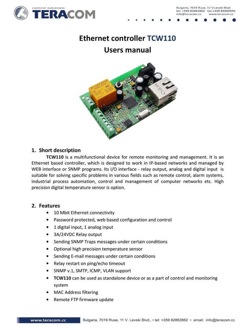
TECHCON TS580D-MM User manual

1
TS580D-MM
Micro-Meter Mix Controller User Guide
technon.com/contact-us
______________________________________________________________________
______________________________________________________________________
Accurately Dispense Two Component (2K) Material
with Dual PC Pump TS8200D Micro-Meter Mix
Dispensing System

2
TS580D-MM
Micro-Meter Mix Controller USER GUIDE
techcon.com/contact-us
Contents
1 Safety ....................................................................................................................................................... 3
2 Symbol Definitions.............................................................................................................................. 4
3 Specifications ....................................................................................................................................... 5
4 Features ................................................................................................................................................. 6
5 Operation............................................................................................................................................... 8
5.1 Connecting the Unit...................................................................................................................... 8
5.2 The Calibration Select Screen .................................................................................................. 9
5.3 Air Pressure Calibration.............................................................................................................10
5.4 Pump Calibration ..........................................................................................................................11
5.5 Pressure Sensor Calibration .....................................................................................................15
5.6 Pressure Adjustment ..................................................................................................................16
5.7 To Change Pressure Unit Display...........................................................................................16
5.8 Manual/Purge Mode.................................................................................................................... 17
5.9 Automatic Dispense Cycle .......................................................................................................18
5.10 Pressure Sensor Setting........................................................................................................... 21
5.11 Cycle Counter .............................................................................................................................. 22
5.12 Stored Program in Memory Cell...........................................................................................24
5.13 Controller Mode and Robotic Mode....................................................................................26
6. Network Settings............................................................................................................................... 27
7. USB –Software Upgrade................................................................................................................29
7.1 OEM –Factory Reset ..................................................................................................................30
7.2 Information Screen.....................................................................................................................30
8. Troubleshooting .................................................................................................................................31
9. Maintenance........................................................................................................................................ 32
10. Limited Warranty ............................................................................................................................33

3
TS580D-MM
Micro-Meter Mix Controller User Guide
technon.com/contact-us
1 Safety
Intended Use:
WARNING: Use of this equipment in ways other than those described in this User
Guide may result in injury to persons or damage to property. Use this equipment
only as described in this User Guide.
OK International cannot be held responsible for injuries or damages resulting from
unintended application of its equipment. Unintended uses may result from taking the
following actions:
•Making changes to equipment that has not been recommended in the User Guide
•Using incompatible or damaged replacement parts •Using unapproved accessories
or auxiliary equipment
Safety Precautions:
•Do not operate this unit in excess of maximum ratings/settings
•Always wear appropriate personal protective clothing or apparel
•The fluid being dispensed may be toxic and/or hazardous. Refer to the Material
Safety Data Sheet for proper handling and safety precautions
•Do not smoke or use open flames when flammable materials are being dispensed
•This equipment is for indoor use only

4
TS580D-MM
Micro-Meter Mix Controller USER GUIDE
techcon.com/contact-us
2 Symbol Definitions
Symbol
Description
Symbol
Description
Home Screen
Dispense both pumps
Settings
Dispense Pump 1 only
Calibration
Dispense Pump 2 only
Not logged in / Login
Screen
Advanced Calibration
Logged in / Login Screen
Factory Reset Settings
E-Stop
Information
Reset Cycle Count
Robotic Mode
Pressure Unit Select
Time/Volume/Weight mode
Volume/Time/Quantity
Select
Interrupt mode
Controller Mode
Teach mode
Run
Purge mode
Run Continuous
Purge Pump 1 mode
Run Sequence
Purge Pump 2 mode
Run Sequence Continuously
Ratio
Continuous/Sequence
Mode Select
Low Pressure Calibration
IOT/RCP/Network
Settings
High Pressure Calibration
USB firmware upgrade
Inlet Pressure
Forward Dispense
Outlet Pressure
Reverse (suck back)
Current to Pump 1
Selected Program
Current to Pump 2
Completed Dispenses

5
TS580D-MM
Micro-Meter Mix Controller User Guide
technon.com/contact-us
3 Specifications
Size
290 mm x 212 mm x 98 mm (11.4” x 8.3” x 3.9”)
Weight
2.8 kg (6.17 lbs)
Input Voltage
24 VDC
Output Voltage Range
0-24 VDC
Rated Power
15 W
Air Input
100 psi (6.9 bar) Max.
Air Output
0-99.9 psi (6.9 bar)
Pollution Degree
II
Installation Category
I
Indoor Use
Altitude up to 2,000 m (6,562 ft)
Operating Temperature
0 ˚C to 50 ˚C (32 ˚F to 122 ˚F)
Storage Temperature
-10 ˚C to 60 ˚C (14 ˚F to 140 ˚F)
Max. Relative Humidity
80% for temperature up to 31 ˚C (87.8 ˚F) Decreasing
linearly to 50% relative humidity at 40 ˚C (104˚F)
Timer
0.008-99.99 seconds
Cycle Mode
Timed, By-Weight, By-Volume, Interrupt, Teach, Purge
Timing Repeat Tolerance
+/- 0.001%
Cycle Rate
Up to 600 cycles/min
Display
Touch Screen, Resistive
Meets or exceeds
CE, TUV and NRTL

6
TS580D-MM
Micro-Meter Mix Controller USER GUIDE
techcon.com/contact-us
To initiate a dispense cycle with voltage
4 Features
Figure 1: Controller Features
•Air Output A/B –Pressurized air to connect to the material syringes. The ports
share a common source.
•Motor Ports C/D –Connected to the motors/pumps, provide drive power to the
motors, and read encoder feedback.
•Air Regulator –Reduce inlet air pressure (100 psi typical) to a desired pressure.
•Air Inlet –Connect to pressurized air source (100 psi typical).
•Air Outlet Unregulated –share pressurized air to auxiliary equipment.
No Connection
No Connection
To initiate a dispense cycle with
contact closure Pin 5 –Pin 6
Pin 1 (+)
Pin 2 (-)
Pin 3
Pin 4
Pin 5
Pin 6
Chassis Ground
Pin 5
Pin 3, 4, 7, 8, and 9 = No Connection
5-24
VDC

7
TS580D-MM
Micro-Meter Mix Controller User Guide
technon.com/contact-us
•Foot Switch Port –Connect external switch to actuate dispenses.
•I/O Port.
•Internet Port –RJ45 connection to Ethernet.
•USB Port –Software Upgrade.
•External Pressure Inputs –connect to pump to monitor material pressure.
CAUTION: A 5-micron filter (TSD800-6) must be installed with the unit to ensure
proper air filtration.
Figure 2: Typical Set Up Diagram
Items Description
1Air Filter
2Pump (not included)
3Syringes of material (not included)
4Power Adapter
5Foot Switch

8
TS580D-MM
Micro-Meter Mix Controller USER GUIDE
techcon.com/contact-us
5 Operation
5.1 Connecting the Unit
1. Connect the power cord and foot switch to the back of the unit.
2. Connect the pumps to Ports C and D. The Left pump is typically connected to
Port C and the Right pump is typically connected to Port D.
3. Connect Syringe air hoses to Ports A and B.
Caution: Port A and B share the same regulated air source. If the viscosity of the resin
is significantly higher than the hardener, please use an external regulated air source for
the resin.
4. Press the Power switch to turn on the unit.
5.1.1 Login
1. From the Home screen, touch the Login icon to enter the Login screen.
2. Enter “0000” in the Password window (Password window should be highlighted
with a green box).
3. Touch green check to accept.
4. Optionally check “Password Disabled”- no further login will be required.
5. Touch the Home screen button to return to the Home screen.
Figure 3

9
TS580D-MM
Micro-Meter Mix Controller User Guide
technon.com/contact-us
Optionally, click the checkbox. No further login will be
required, and lockout will not occur until the box is unchecked explicitly.
To change the password, click on the Gear then enter the old, then new
password.
5.2 The Calibration Select Screen
From the Home screen button, touch the calibration button . You will see the
Calibration Select screen.
Figure 5: Resetting the Password
Figure 4: Password Screen

10
TS580D-MM
Micro-Meter Mix Controller USER GUIDE
techcon.com/contact-us
5.3 Air Pressure Calibration
Note: Pressure calibration must be performed when the unit is activated for
the first time.
From the Home screen button, touch the calibration button then select
AIR PRESSURE CAL.
1. Reduce the air pressure at the rear air inlet port to zero (0) PSI. Touch the ‘LOW
(0)’ pressure measurement box. Note: Inside the yellow box is the internal
unitless pressure measurement. It will be updated.
2. Increase the air pressure at the rear air inlet port to 100 PSI (6.89 BAR). Touch the
‘HIGH (100)’ measurement box. The ‘HIGH (100)’ measurement box on the right
will be updated.
Figure 6: Calibration Select Screen
Figure 7: Air Pressure Calibration Screen

11
TS580D-MM
Micro-Meter Mix Controller User Guide
technon.com/contact-us
3. The calibration is complete. Touch the Home button to return to the Home
screen.
4. Touch the red to go back to the Calibration Selection screen.
5.4 Pump Calibration
Calibration allows the controller to determine correct volume/weight of the material
dispense out of the pumps. Calibration must be performed for the following event:
•New pump installation
•New rotor replacement
•New stator replacement
•A new material is to be dispensed
•After the pump has been used for a period of time
A. PUMP 1 CALIBRATION (P1)
Note: To ensure dispense accuracy, the calibration process must be done at low, mid,
and high flow rate.
5.4.1 Calibration at MID Flow Rate:
1. Attach the calibration nozzle to the pump.
2. From the Calibration Select screen, touch to calibrate Pump 1.

12
TS580D-MM
Micro-Meter Mix Controller USER GUIDE
techcon.com/contact-us
You will see the following screen with the check mark appear in the MID flow
rate box.
3. Place a small container under pump 1 outlet
4. Press the Run button to activate pump 1.
5. Weigh the dispensed material.
6. Touch the Box next to the “Actual wt.”
7. The screen below will appear. Proceed to enter the weight collected in Step #5 in
this screen.
Figure 8: MID flow rate box
Figure 9: “Actual wt”

13
TS580D-MM
Micro-Meter Mix Controller User Guide
technon.com/contact-us
8. Touch the Accept button in the numeric entry screen.
9. Touch the Accept button in the P1 Calibration screen to record the value.
10. Touch the Accept button in the Confirmation popup.
11. Verify the value in the grey ‘Current Value:’ box is the same as the value entered.
5.4.2 Calibration at LOW Flow Rate:
1. Touch the AC (Advanced Calibration) button . You will see the advanced
calibration screen:
Figure 10: Enter collected weight here
Figure 11: Saving P1 Calibration

14
TS580D-MM
Micro-Meter Mix Controller USER GUIDE
techcon.com/contact-us
2. Verify the ‘Low’ box is checked.
3. Repeat Step # 2 to 10 in section 5.4.1 above.
5.4.3 Calibration at HIGH Flow Rate:
1. Touch the AC (Advanced Calibration) button . You will see the advanced
calibration screen:
2. Verify the ‘HIGH’ box is checked.
3. Repeat Step # 2 to 10 in section 5.4.1 above.
4. The Pump 1 calibration is complete.
5. Touch the red ‘X’ to return to the calibration selection screen.
B. PUMP 2 CALIBRATION (P2)
1. From the calibration select screen select ‘P2 CAL’
2. Repeat steps in Section 5.4.1, 5.4.2 and 5.4.3 above.
3. Pump 2 Calibration is complete.
4. Touch the Home button to return to the home screen.
13
Figure 12: Advanced Calibration Screen (LOW)
Figure 13: Advanced Calibration Screen (HIGH)

15
TS580D-MM
Micro-Meter Mix Controller User Guide
technon.com/contact-us
5.5 Pressure Sensor Calibration
The pressure sensors are offered as optional accessories to measure the material
pressure differential between the two pumps. When the mixing nozzle is restricted
and started to clog, the material will flow upstream, causing cross-contamination.
When this event occurred, the material pressure differential will increase significantly.
The pressure sensors will send the signal to the controller shut down to pump.
Preparation
NOTE: In order for pressure sensing to be operational, the Max. Pressure Differential
setting must be non-zero. Please refer to Section 5.10.
•Ensure the Pressure Differential value is set to a non-zero value.
•External pressure sensors should be attached to the pumps and connected to the
rear panel.
•The pumps should be prepared to dispense as desired (Rate and Ratio).
•Purge Mode should be selected.
1. From the calibration select screen, click on . You will
see the External Pressure Calibration Screen.
2.Press the button to clear any existing calibrations.
3. Press and hold the Footswitch or close the contact closure on the rear panel or
apply 5-24V on the rear panel input. Do this for approximately 3 seconds. You
should see numbers update on the front panel.
4. While dispensing, press the button.
Figure 14: External Pressure Calibration Screen

16
TS580D-MM
Micro-Meter Mix Controller USER GUIDE
techcon.com/contact-us
The calibration is complete. The Micro-Meter Mix will now stop dispensing if the
pressure differential (or absolute pressure) exceeds the values set on the external
pressure page (page 6) of the Program Profile Setup.
5.6 Pressure Adjustment
Note: Pressure on port A and B provides constant regulated pressure. These two
pressure outlets can be used to pressurize the fluid reservoir to feed fluid to Pump 1
and Pump 2. Please note that the pressure output is the same on both ports.
If the viscosity of the resin is significantly higher than the hardener, then use external
pressure regulator to control the resin.
1. Rotate the pressure regulator knob clockwise to increase the pressure.
2. Rotate the pressure regulator knob counterclockwise to decrease the output
pressure. The output pressure will display in the A/B section located on the
bottom left-hand corner.
5.7 To Change Pressure Unit Display
Note: The default pressure unit is PSI. To change pressure unit to BAR, follow the
instructions below.
1. From the Main screen, touch the Setup Icon to enter Setup screen.
2. Press “PSI/BAR” Icon to change the pressure unit.
Figure 15: Output Pressure Display

17
TS580D-MM
Micro-Meter Mix Controller User Guide
technon.com/contact-us
3. Press “Change” Icon to change the pressure units
5.8 Manual/Purge Mode
There are 3 Purge options:
•= To purge both pumps
•= To purge pump 1
•= To purge pump 2
Figure 16: Setup screen
Figure 17: Press “Change” to change the pressure units

18
TS580D-MM
Micro-Meter Mix Controller USER GUIDE
techcon.com/contact-us
5.9 Automatic Dispense Cycle
The Micro-Meter Mix can be setup to run in Timed mode, Volume mode or Quantity
(Weigh) mode.
Touch the setup icon to enter the setting screen.
•Select V for Volume mode
•Select T for Timed mode
•Select Q for Quantity (Weight) mode
5.9.1 Volume Mode
1. Touch the Dispense volume box to enter the desired dispense volume.
2. Touch the Suckback Volume box to enter the desired suckback volume.
3. Press the Green check mark to save the data.
Purge
icons
Figure 18: Purge icons
Figure 19: Setup screen

19
TS580D-MM
Micro-Meter Mix Controller User Guide
technon.com/contact-us
5.9.2 Timed Mode
1. Touch the Dispense Time box to enter the desired dispense time in seconds.
2. Touch the Suckback Time box to enter the desired suckback time in seconds.
3. Press the Green check mark to save the data.
5.9.3 Quantity Mode
1. Touch the Dispense Weight box to enter the desired dispense weight in
grams
2. Touch the Suck back Weight box to enter the desired Suck back weight in
grams
3. Press the Green check mark to save the data
Figure 20: Setting Dispense and Suckback Volumes
Figure 21: Setting Dispense and Suckback Time

20
TS580D-MM
Micro-Meter Mix Controller USER GUIDE
techcon.com/contact-us
Figure 22: Settings (Weight Mode)
5.9.4 Pause Time
This function is not available at this time. When available, this function will allow the
operator to set delay time between dispense and suckback.
5.9.5 Pump 2 Flow Rate Adjustment (P2 Adjust)
In some cases, after calibration is done, the mix ratio between the 2 pumps is still
slightly off. This function allows the operator to manually change the flow rate of
Pump 2 to align the mix ratio between the 2 pumps.
1. Enter the Mix Ratio
2. Touch the Up arrow to increase the flowrate of Pump 2
3. Touch the down arrow to decrease the flowrate of Pump 2
4. Touch the green check mark to save the data
Figure 23: Setting Pause Time (not yet available)
Table of contents
Popular Controllers manuals by other brands
Ingersoll-Rand
Ingersoll-Rand TS1401 Series Installation and maintenance information
Inverter
Inverter MPPT Series user manual
janitza
janitza Prophi 6R manual
Ewellix
Ewellix CAHB-2 Series Installation, operation and maintenance manual

Hall Research Technologies
Hall Research Technologies VSA-31-IP manual
HP
HP E-MSM720 installation guide
Mitsubishi Electric
Mitsubishi Electric Melsec-F FX2NC Series Hardware manual
Woodward
Woodward VariStroke-I Installation and operation manual
Auber
Auber TD400P instruction manual
Allen-Bradley
Allen-Bradley PowerFlex 400 Technical data
THOMSON
THOMSON TSC 900 Installation, operating & service manual
Gemo
Gemo DT109PX Installation & use
