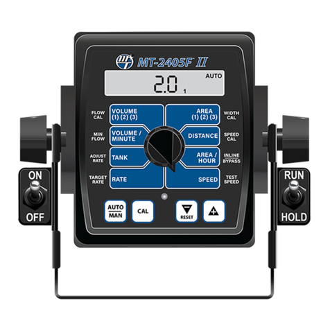
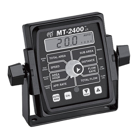
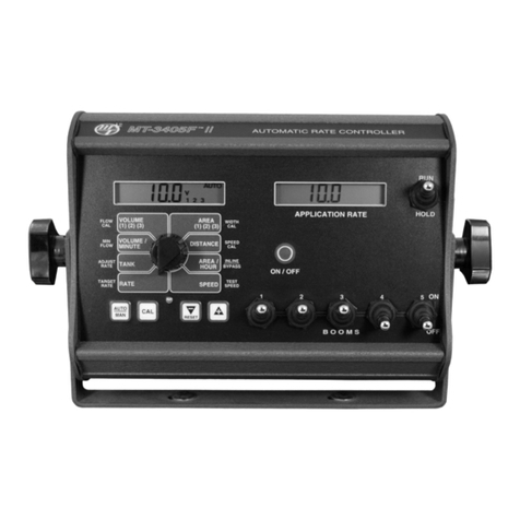
micro-trak MT-3405 F II User manual

MT-3405F™II
“Dual Display”
Automatic Rate Controller
OperatiOn and CalibratiOn
referenCe Manual

2
Table of Contents
Table of Contents ...................................................................................................................................................................... 2
Console Functions..................................................................................................................................................................... 3
Calibration ...............................................................................................................................................................................4-9
English/Metric Selection..........................................................................................................................................................................4
Calibration Key Function .........................................................................................................................................................................4
Entering Calibration Values ................................................................................................................................................................4-6
Radar or GPS Speed Sensor Calibration ....................................................................................................................................6
Determining the Speed Cal............................................................................................................................................................7
Drive Shaft Speed Sensor Calibration ........................................................................................................................................7
Test Speed............................................................................................................................................................................................7
Exiting Calibration.............................................................................................................................................................................7
Factory-loaded Calibration Values ..............................................................................................................................................7
Special Calibration .................................................................................................................................................................................8-9
Operation............................................................................................................................................................................ 10-12
Manual Operation............................................................................................................................................................................................ 10
Automatic Operation ............................................................................................................................................................................. 11
Data Displayed in Rotary Switch Positions .................................................................................................................................... 11
Resetting System Counters..................................................................................................................................................................12
Clearing Counters....................................................................................................................................................................................12
Notes ...............................................................................................................................................................................................................13

3
Overview of MT-3405FTM II Console Functions
The MT-3405F™ II features two large, easy-to-read liquid crystal displays and a lighted panel for night use.
The right-hand display always shows the application rate and the left-hand display shows data selected by the
rotary switch. Press the On/Off button to turn console on or off.
VOLUME 1 2 3: Displays total gallons (liters) or lbs. (kg)
of NH3 applied. May be reset. (Note: VOLUME and AREA
counters work in pairs, if VOLUME counter 1 is reset, it also
resets AREA counter 1).
TANK: Displays gallons
(liters) of liquid remaining
or lbs. (kg) of NH3
remaining.
MIN FLOW: Used in the calibration mode to enter the
minimum flow rate (GPM/LPM) of the spray boom.
ADJUST RATE: Used in calibration mode to enter an
amount of change for on-the-go adjustments to the target
rate (GPA/LPH), or lbs/acre (kg/hectare) N.
TARGET RATE: Used in calibration mode to enter the target
application rate (GPA/LPH) or lbs/acre (kg/hectare) N.
AREA 1 2 3: Keeps a running count of the total acres
(hectares) worked. May be reset. (Note: VOLUME and AREA
counters work in pairs, if AREA counter 1 is reset, it also resets
VOLUME counter 1).
AREA/HOUR: Displays
current work rate in acres
per hour (hectares per
hour).
WIDTH CAL: Used in calibration mode to
enter the working width of your sprayer
booms or other equipment.
SPEED: Displays ground
speed in miles per hour
(kilometers per hour).
SPEED CAL: Used in calibration mode to enter the speed
calibration number in inches (cm) per pulse.
INLINE/BYPASS: For establishing servo polarity. (If servo is
in the main spray line, select “Inline”. If servo is installed in a
return line, select “Bypass”.)
TEST SPEED: Used in calibration mode to enter a test speed
in miles per hour (kilometers per hour).
AUTO/MAN:
Key which changes
operation from
automatic control
to manual.
CAL:
This key is used
to enter & exit the
calibration mode.
Key Functions:
PROGRAM KEYS:
Used to increment
and decrement the
different calibration
values.
in CAL, clears the
selected counter
when held for
two seconds.
e
“+” key increases
and the“-”
decreases the
value displayed.
FLOW CAL: Used in calibration mode to
enter the calibration value assigned to
your flowmeter (see flowmeter tag.)
Calibration Positions
ON / OFF
RUN/HOLD SWITCH: Selecting the RUN position will
turn on all active boom valves for AUTO or MANUAL control
operation. (Boom switches must be in the up (ON) position.)
Selecting the HOLD position will shut off all active boom
valves. (Boom switches may remain in the up (ON) position.)
The HOLD position is the master hold for the system. It
will override a RUN condition from any remote run/hold
switches connected to the system.
BOOM SWITCHES: The console accumulates area based
is turned OFF, the respective width is subtracted from the
total width to accumulate area based on the new active
application width. If a boom switch is ON (up), its respective
boom shut off valve should be on. If a boom switch if OFF
(down), its respective boom shut-off valve should be off. No
shut-off valves should be ON if the Run/Hold switch is in
HOLD, or in RUN and AUTO while speed is zero.
VOLUME/MINUTE: Displays
total gallons (liters) of liquid
applied per minute, or lbs. (kg)
NH3 per minute.
DISTANCE: Displays distance
traveled in feet (meters). May
be reset.
RATE: Displays application
rate GPA(LPH), or lbs. N/acre
(kg of N/hectare).
Calibration Positions
AUTO
MANCAL
RESET
Indicates over or
under application of plus or minus
10% from the Target Rate or if the
tank is low. Also lit when in CAL.
ON/OFF:
Press to turn the
console ON or
OFF. Left-hand
display shows
hours of operation
for 2 seconds, then
software version
for 2 seconds, then
begins normal
operation.

4
Illustration 12
Calibration - Loading Default Calibration Values
NOTE: In metric, the width will have a decimal point, in
English there is no decimal point. Also, changing from
English to Metric mode may change or alter any previously
entered calibration values. After switching measurement
modes, confirm that all calibration values are correct.
WIDTH
CAL
FLOW
CAL
MIN
FLOW
ADJUST
RATE
TA RGET
RATE
SPEED
CAL
INLINE
BYPASS
TEST
SPEED
VOLUME /
MINUTE DISTANCE
AREA /
HOUR
VOLUME
(1) (2) (3)
RATE SPEED
AREA
(1) (2) (3)
ON
OFF
12345
B O O M S
RUN
HOLD
CAL
AUTO
MANRESET
V 1 2 3 4 5
ON / OFF
____
APPLICATION RAT E
TANK ___
CAL HOLD
Press to
enter or exit
calibration
mode.
Press to increase or
decrease values.
Red warning light will
be lit when in CAL.
Illustration 11
WIDTH
CAL
FLOW
CAL
MIN
FLOW
ADJUST
RATE
TA RGET
RATE
SPEED
CAL
INLINE
BYPASS
TEST
SPEED
VOLUME /
MINUTE DISTANCE
AREA /
HOUR
VOLUME
(1) (2) (3)
RATE SPEED
AREA
(1) (2) (3)
ON
OFF
12345
B O O M S
RUN
HOLD
CAL
AUTO
MANRESET
MANAUTO
CALHOLD
V 1 2 3 4 5
ON / OFF
____
APPLICATION RA T E
TANK ___
English or Metric?
The MT-3405FTMII is capable of displaying information in
American English or standard Metric measurement. The
MT-3405FTMII is shipped from the factory programmed for
English. NOTE: The following procedures will also load
factory default calibration values. To simply change units
without loading defaults, see the “Special Calibration”
section.
METRIC
To activate the Metric mode, turn power OFF and place
the rotary switch at “AREA.” Hold down both the “CAL”
and “-” keys and turn power ON. See Illustration 11.
The console will display LOAd. Once LOAd is displayed,
release the two keys. To “lock-in” Metric mode you must
enter and exit calibration. Press and hold the CAL key
until “CAL” icon appears on the display. The console is
now in calibration and Metric mode is selected. Exit
CAL by pressing and holding the “CAL” key until CAL
disappears from the display (approximately 1 second).
NOTE: You must exit CAL to lock in Metric units.
ENGLISH
Cal. To activate the English mode, turn power OFF and
place the rotary switch in the VOLUME position. Hold
down both the “CAL” and “-” keys and turn power ON.
The console will display LOAd. Once LOAd is displayed,
release the two keys. To “lock-in” English mode you
must enter and exit calibration. Press and hold the CAL
key until “CAL” lights on the display. The console is now
in calibration and English mode is selected. Exit CAL by
pressing and holding the “CAL” key until CAL disappears
from the display (approximately 1 second). NOTE: You
must exit CAL to lock in English units.
Entering Calibration Values
To enter or change any of the system’s calibration values,
you must enter calibration mode. To enter calibration mode,
STOP the vehicle, turn all booms OFF or put the console in
HOLD and press and hold the CAL button until the “CAL” icon
appears (approximately one second). (NOTE: Calibration
may be entered while moving, but it is not recommend-
ed to attempt calibration while the vehicle is moving.)
The console will remain in calibration mode, with the RED
warning light illuminated until you exit calibration or turn
power OFF.
Once in calibration mode, you may change any one, all, or
none of the values, in any order.*To select a calibration
position, simply turn the rotary selector to the desired
labeling on each side of the rotary selector. All values are
entered and adjusted using the “+” and “-” buttons on the
front panel.
*TEST SPEED MUST BE LAST.
Hold the “CAL” key again for 1 second to exit calibration.
“CAL” will disappear from the display.
NOTE: you must exit CAL to save changes.

5
properly with the MT-3405F™ II console. This number is
stamped on the metal tag attached to the flowmeter. See
Illustration 13. This is a starting point only. If your spray
solution has a specific gravity or viscosity that is different
than water, flowmeter calibration should be done for the
specific solution (Please refer to Fine-Tuning Flowmeter
Calibration in Appendix C on page 45.)
Illustration 13
Calibration (cont)
Entering Calibration Values (cont)
TARGET RATE: Enter the value for the desired target
application rate in
gallons per acre (liters
per hectare) or lbs. of
N per acre (kgs of N per
hectare). This is the
application rate that
the console will lock
onto when operating in
AUTO.
TARGET
RATE RATE
ADJUST RATE: Enter the value for the desired amount of
change in gallons per acre (liters per hectare) to be used
for making on-the-go
rate adjustments when
operating in AUTO.
For example, if a value
“1.0” is entered, you
will be able to increase
or decrease your
application rate in one-gallon (liter) or lb. (kg) increments
during operation in AUTO. To disable this feature, simply
enter “.0” for a value.
ADJUST
RATE TANK
MIN FLOW: The purpose of this calibration value is to
prevent the system from applying below the recommended
minimum rate for the nozzles. The minimum flow rate
in gallons per minute
(liters per minute)
based on the nozzles
being used, for the
entire boom on the
sprayer. DO NOT enter
the actual flow of your
spray application. FOR EXAMPLE: If the minimum flow rate
for the nozzle you are using is .22 GPM at their minimum
recommended pressure and your boom has 20 nozzles, enter
NOT apply at a rate lower than this value when spraying
in AUTO. This value should be checked/ changed for each
different nozzle that you use.
APPLICATION NOTE: Over-application may occur with
MIN
FLOW
VOLUME /
MINUTE
FLOW CAL: This position is used to calibrate the
flowmeter for accurate
liquid measurement.
FLOW
CAL
VOLUME
(1) (2) (3)
CAUTION: If spray lines are pressurized, nozzles may
spray during WIDTH calibration (below).
WIDTH: Enter the effective working width, in inches (meters) for
the boom section currently shown on the display. It is simplest
to start with all booms ON and then turn each boom OFF,
from left to right, after calibrating the width. Note that the
system must be in RUN
(not HOLD) to display
boom numbers. Repeat
this procedure for each
boom section. Enter a
value of “0” (.000) for any
unused boom sections.
of nozzles on the boom section times the nozzle spacing in
inches (mm). For example, if you have 7 nozzles spaced at 20
inches, the working width of the boom section is 140 inches.
WIDTH
CAL
AREA
(1) (2) (3)

SPEED CAL FOR RADAR OR GPS SPEED SENSORS:
See the following table for SPEED CAL numbers to enter for
various radar models or GPS speed sensors. To fine tune the
SPEED CAL number, see Appendix B on page 44.
WIDTH
CAL
FLOW
CAL
MIN
FLOW
ADJUST
RATE
TA RGET
RATE
SPEED
CAL
INLINE
BYPASS
TEST
SPEED
VOLUME /
MINUTE DISTANCE
AREA /
HOUR
VOLUME
(1) (2) (3)
RATE SPEED
AREA
(1) (2) (3)
ON
OFF
12345
B O O M S
RUN
HOLD
CAL
AUTO
MANRESET
ON / OFF
____
APPLICATION RA T E
TANK ___
MANAUTO
CAL HOLD
Illustration 14
SPEED CAL: This position is used to calibrate the speed
this position is selected,
the display will show
the SPEED CAL value
along with “CAL” on the
display. See Illustration
14. In English units, the
SPEED CAL number is
displayed in inches, in metric it is displayed in centimeters.
SPEED
CAL
DISTANCE
INLINE/BYPASS:
Use the “+” or “-” buttons to toggle to desired selection.
Inline is used when the servo is in the line going out to the
booms; Bypass is used
when the servo is in a
return line. NOTE: if
used on a Micro-Trak
NH3 system, it must be
set to Bypass.
INLINE
BYPASS
AREA /
HOUR
Radar or GPS Speed Sensor Calibration
Radars English Cal # in. Metric Cal # in. Hz/MPH
Vansco .150 .38 58.90
Raven .148 .38 59.80
Magnavox .154 .39 57.40
Dickey-john
(NOTE: Dickey-john
radars may be factory
calibrated for any of
these four settings).
.149 .38 58.94
.199 .51 44.21
.319 .81 27.64
.518 1.32 17.034
GPS Speed
Astro II & 5 .189 .48 46.56
SkyTrak (Std) .150 .38 58.94
SkyTrak (MT) .910 2.31 9.82
Dickey-john .210 .53 42.00
John Deere (In-cab speed signal) .197 .50 44.70
6
Calibration (cont)
Entering Calibration Values (cont)

Drive Shaft Speed Sensor Calibration
NOTE: If you have mounted the magnetic speed sensor on
a wheel, skip this step and go on to Fine Tuning Speed/
Distance Calibration Values.
Because of the difference in wheel-to-drive shaft ratios, it is
difficult to determine a calibration value for installation on
estimated calibration value and then fine-tune the calibration.
Any number between 10 and 15 (255 mm to 380 mm) is a
good starting value.
NOTE: For fine-tuning the SPEED CAL value, see Appendix B
on page 44.
Illustration 15
To determine SPEED CAL, measure the distance of
one complete wheel revolution and divide by the
number of magnets installed.
For the console to calculate the correct speed and measure
distanceaccurately,thecircumferenceofthesensor-equipped
wheel must be entered. Determine the circumference of the
sensor-mounted wheel to the nearest tenth of an inch (tenth
of a centimeter) with the following method:
METHOD
Mark the tire with a piece of chalk and measure the distance
traveled on the ground for one complete revolution. See
Illustration. For improved accuracy, it is recommended that
you perform this function in field conditions, measure several
revolutions, and take the average.
Divide the measured revolution by the number of magnets
installed to get your starting SPEED CAL calibration value.
Once calibration of the system is complete, this number
should be fine-tuned for optimum accuracy.
For fine-tuning the SPEED CAL value, see Appendix B on page 44.
7
EXITING CALIBRATION: Upon completion of the calibra-
tion process, exit calibration by pressing and holding the
CAL button until the RED warning light turns off (one sec-
ond). Basic calibration is now complete. BEFORE beginning
application, confirm that the system is set up to do the
job that you want it to. Please refer to Pre-Field System
Checkout to confirm calibration settings, nozzle selection
and overall system performance. NOTE: You must exit CAL
to save any changes.
TEST SPEED: Test speed is a built-in ground speed simulator
operating speed is
entered, the MT-3405F
II will respond as if you
were actually driving
that speed. It allows
you to simulate your
spraying application
with water, while
remaining stationary, to
make certain that all of the equipment is operating properly and
that your sprayer can actually perform the intended application.
Test speed will not accumulate Distance or Area measurements.
(The CAL indicator flashes to remind the user that TEST SPEED
mode is active.) TEST SPEED is cancelled by exiting CAL.
TEST
SPEED
SPEED
Calibration Factor Measurements Effected Default Values
English Metric
TARGET RATE Application Rate in Auto 10.00 gallons/acre 100.00 liters/hectare
ADJUST RATE Amount of increase or decrease per +/- press (in auto) 1.00 gallons/acre 10.00 liters/hectare
WIDTH BOOMS 1-3* Area, Application Rate 240 inches 6.000 meters
SPEED CAL Distance, Area, App. Rate, Area/Hour 0.189 inches 4.44 centimeters
MINimum FLOw App. Rate, Lowest Allowable Flow Rate 0.0 gallons/minute 0.0 liters/minutes
FLOW CALibration Flow/App. Rats, Volume 145.0 pulses/gallon 145.0 pulses/gallon
INLINE/BYPASS Application Rate Bypass Bypass
TEST SPEED none 0.00 0.00
* BOOMS 4 AND 5 ARE SET TO 0.
Calibration (cont)
Determining the SPEED CAL
Factory-Loaded Calibration Values
8
The “Special” calibration mode is used to set up system
parameters that rarely need to be changed or adjusted. To
enter Special Cal, put the system in HOLD, turn the console
OFF, press and hold both the AUTO/MAN button and CAL
button while turning console ON. The console will display
SPEC for 2 seconds to show that the console is in the Special
Calibration mode. Release the AUTO/MAN and CAL buttons.
NOTE: The following table describes the “Special” Cal
parameters and shows the factory settings. More detailed
descriptions follow the table.
“Special” Calibration
Parameter Description Factory Setting
Units System of Units EnG (English) or mEt (Metric) / TurF (Turf) EnG (English)
Valve Voltage Servo Valve Drive Voltage (8/12) 12
Material Choose Liquid (H2O) or Anhydrous (NH3) H2O
Valve Response Speed Set Valve Response (-4 to 3) -1
Fill Tank Size Size (volume) of Full Tank (Off or 1-65,535) Off
Tank (Low) Set Point Sets Alarm Set Point if using TANK Function (Off or 1-65,535) Off
Auto Shut-off Runs Servo Toward Minimum when in Hold (On/Off) Off
Auto Delay Time Delay Servo Response when going from Hold to Run (Off to 4 sec.)
Allows slow shutoff valves enough time to open before adjusting servo 1
WIDTH
CAL
FLOW
CAL
MIN
FLOW
ADJUST
RATE
TARGET
RATE
SPEED
CAL
INLINE
BYPASS
TEST
SPEED
VOLUME /
MINUTE DISTANCE
AREA /
HOUR
VOLUME
(1) (2) (3)
RATE SPEED
AREA
(1) (2) (3)
CAL
AUTO
MANRESET
____
TANK ___
AUTO
1
Special Cal Special Cal
Fill Tank Size
Tank Set Point
Auto Shut-off On/Off
Auto Delay Time
Units
Valve Voltage
Material
Valve Response Speed
Calibration parameter(s) can then be accessed with the rotary
switch per the illustration below. To exit Special Calibration,
press and hold the CAL button for 2 seconds. The console
will store any changes and revert to normal operation.
NOTE: you must exit Special Calibration to save changes.

1” old servo
8 volts
¾” old servo
8 volts
1” Electric Servo
12 volts
9
To exit “Special” Calibration, press and hold the CAL button
for 2 seconds. The console will store any changes and revert
to normal operation.
NOTE: you must exit “Special” Calibration to save
changes.
Units: Choose the system of units desired. Turf units are
the same as English units except Area is in thousands of
square feet. Use the “+”
and “-” buttons to choose
between EnG (American
English Units), MEt (Metric)
and TurF (Turf units).
WIDTH
CAL
AREA
(1) (2) (3)
Valve Voltage: Selects the operating voltage for the servo
valve. Factory setting is 12 volts. Use the “+” and “-” buttons
to toggle between 8 and 12
on display. NOTE: if using
an old style Micro-Trak
servo valve, (See Illustration
below), set to 8 volts.
SPEED
CAL
DISTANCE
Material: Use “+” and “-” buttons to select between liquid
(H2O displayed) or anhydrous ammonia (nH3 displayed). If
in NH3 mode, rates will be displayed in pounds (kg) actual N
and totals will be displayed
in pounds (kg) anhydrous
ammonia (NH3). NOTE:
if NH3 is selected, see
Appendix F for NH3 specific
instructions.
INLINE
BYPASS
AREA /
HOUR
Valve Response Speed: Allows adjustment of response
to “tune” the system for use with very fast or slow valves.
For example, if using a ball valve that takes several seconds
to open or close in manual mode, and the system responds
sluggishly, use the “+” button
to adjust the valve response
number to 1, 2, or 3. The range
of adjustment is -4 to 3, factory
setting is -1. NOTE: exercise
caution when increasing the
valveresponse speed. Ifusing
a relatively fast valve (1-3
seconds open-to-close), the system may become unstable
with higher valve response speed numbers entered.
TEST
SPEED
SPEED
Fill Tank Size: If using the Tank feature, this setting can
be used to enter the volume of the tank. Use the “+” and
“-” buttons to choose OFF or any value from 1-65,535. Then
when the tank is filled,
the tank counter can be
reset to full by simply
turning the rotary switch
to the TANK position
and pressing the “+”
button. Depending on
the “UNITS” setting, the
TANK SIZE units will be either gallons or liters. If “material”
is set to NH3, the Tank Size will be in lbs. or kg. Anhydrous
Ammonia (NH3).
FLOW
CAL
VOLUME
(1) (2) (3)
Tank Alarm Set Point: Use the “+” and “-” buttons to
set the desired value. This value sets the level at which the
drops below the set point,
the alarms will notify the
user that the tank level is
low.
MIN
FLOW
VOLUME /
MINUTE
Auto Shutoff ON/OFF:
the servo will run toward minimum flow for 4 seconds any
time the system is put in
HOLD or all booms are
turned off, or if in AUTO
mode and speed goes
to zero. This feature is
normally used only in Dry
Application systems where the HOLD condition must stop a
hydraulic auger or conveyor belt.
ADJUST
RATE TANK
Auto Delay Time: Typically used when using relatively slow
ball valves for boom shut-off, this feature delays adjustment
of the servo valve until
the boom valves are open.
Use “+” and “-” buttons to
set from zero (OFF) to 4
seconds.
TARGET
RATE RATE
“Special” Calibration (cont)

Makesure your systemis properly calibrated before beginning
Pre-Field System Checkout described on pages 39-40 prior
to beginning any field operations.
Press the ON/OFF button to turn the console on. After
displaying the hours of operation and software version, the
console will start normal operating mode.
The MT-3405F™ II can be operated in Manual (MAN) or
Automatic (AUTO) mode. In either mode, the right-hand
display will always show the Application Rate (except
when in HOLD or when displaying error messages, see
Troubleshooting section starting on page 33). The left hand
display will show data as selected by the rotary switch.
Manual Operation
The manual mode is used when the operator wants to
manually control the servo valve using the “+” and “-” keys,
and thus the application rate. The application rate (gal/acre
or liter/hec) will vary depending on ground speed. Use the
AUTO/MAN button to select MANual mode (“MAN” icon will
be displayed).
IN HOLD: If the console is in HOLD, or if all Boom Valves are
OFF, the “+” and “-” buttons will not control the servo valve
unless the rotary switch is in the VOLUME/MINUTE position.
In that position only, the servo valve can be adjusted without
any boom valves on. This can be useful for system pressure
tests, etc.
IN RUN, WITH SPEED SIGNAL: If the system is in RUN,
with at least one boom valve ON and there is a speed signal,
the “+” and “-” buttons can be used to adjust the servo valve
with the rotary switch in any position except TANK, VOLUME,
and AREA and the application rate can be monitored on the
right-hand display.
IN RUN, NO SPEED SIGNAL: If there is no speed signal,
“no SPEEd” will flash in the right-hand display and the
Application Rate will be invalid. The “+” and “-” buttons will
adjust the servo valve if the rotary switch is in the VOLUME/
MINUTE position, and the flow rate (GPM or LPM) can be
monitored.
Turn rotary dial to display desired readout.
WIDTH
CAL
FLOW
CAL
MIN
FLOW
ADJUST
RATE
TARGET
RATE
SPEED
CAL
INLINE
BYPASS
TEST
SPEED
VOLUME /
MINUTE DISTANCE
AREA /
HOUR
VOLUME
(1) (2) (3)
RATE SPEED
AREA
(1) (2) (3)
ON
OFF
12345
B O O M S
RUN
HOLD
CAL
AUTO
MAN RESET
ON / OFF
____
APPLICATION RATE
TANK ___
HOLD
V 3
Operation
10

the servo valve to maintain the desired application rate
(GPS/LPH) when the vehicle speed changes or when booms
are turned on or off. Press the AUTO/MAN button to select
AUTOMATIC mode; the AUTO icon will appear in the display.
To operate the system in AUTOMATIC mode, turn on the
desired booms, toggle the RUN/HOLD switch to RUN, and
drive. IMPORTANT NOTE: In AUTO mode, when no speed
signal is available, the system automatically turns all
booms off. “no SPEEd” will flash in the right-hand display
until the vehicle starts moving, then the console will turn the
booms on and the Application Rate will be displayed in the
right-hand display. The system will automatically adjust the
servo valve to maintain the calibrated TARGET RATE (GPA/LPH).
ON-THE-GO “DELTA” RATE ADJUSTMENTS (ADJUST
RATE): To adjust the target application rate on-the-go,
each time the “+” or “-” buttons are pressed, the TARGET
RATE will be increased or decreased by the amount of the
ADJUST RATE which was entered in calibration. Example:
GPA, pressing the “+” key once will increase the target rate
from 10.0 to 11.0. The rate display will momentarily show the
new target rate of 11.0 and then show the actual application
rate. Pressing the “-” key once will decrease the target from
11.0 to 10.0. NOTE: When you “DELTA” the target rate, the
display will momentarily show you the new target rate
and then resume showing the actual application rate. The
new target rate is maintained until further adjustments
are made using the “DELTA” feature or calibration changes
occur, or if the unit is turned off. Important: to use the
DELTA feature, the console must be in AUTOMATIC mode
and the rotary switch can be in any position except TANK,
VOLUME, or AREA.
IN HOLD: If the system is in AUTO mode and in HOLD or
all booms are off, the “+” and “-” buttons will adjust the
TARGET RATE with the rotary switch in any position except
TANK, VOLUME or AREA; CAUTION: we recommend that
the rotary switch is in the RATE position, because that is
the only position where the new TARGET RATE is displayed
while in HOLD. In RATE position, the left-hand display will
momentarily display the new TARGET RATE, then will revert
to .00, because all the boom valves are off so there is no
product being applied.
USING THE TANK COUNTER:
the TANK position, the left-hand display shows the amount
remaining in the tank. If a FILL TANK SIZE (tank full) number
has been entered in Special Calibration, the “AUTO FILL”
feature is active; this feature allows the TANK counter to
be quickly reset to a full tank amount by simply pressing
the “+” button with the rotary switch in the TANK position.
The “-” button can be used to reduce the tank counter, but
any press of the “+” will set the counter to the calibrated
FILL TANK SIZE value.
If no TANK VALUE has been entered in calibration, the tank
counter can still be used, but the counter must be manually
adjusted when filled, by pressing and holding the “+” button
until the desired value is reached.
Turn rotary dial to display desired readout.
WIDTH
CAL
FLOW
CAL
MIN
FLOW
ADJUST
RATE
TARGET
RATE
SPEED
CAL
INLINE
BYPASS
TEST
SPEED
VOLUME /
MINUTE DISTANCE
AREA /
HOUR
VOLUME
(1) (2) (3)
RATE SPEED
AREA
(1) (2) (3)
ON
OFF
12345
B O O M S
RUN
HOLD
CAL
AUTO
MAN RESET
ON / OFF
____
APPLICATION RATE
TANK ___
Operation (cont)
Automatic Operation
11
TANK ALARM: If a TANK SET POINT (tank low) number has
been entered in Special Calibration, the TANK ALARM feature
TANK SET POINT, the red warning light will flash and “FILL”
will flash on the left-hand display. The “FILL” message will
flash no matter what position the rotary switch is in. Adjusting
the tank value to a value greater than the SET POINT will turn
the alarm off.
In TANK position, press”+” to
enter full tank amount.
DATA DISPLAYED IN ROTARY SWITCH POSITIONS
(See the NH3 section in the Appendix for NH3 data
description.)
RATE: Actual number of gallons per acre (liters per hectare)
being applied.
TANK: Amount (gal or lit) remaining in tank.
VOLUME/MINUTE: Flow rate in GPM (LPM).
Three independent pairs of counters.
In either the AREA or the VOLUME
position, select a pair of counters by
pressing the “+” button. The active pair of counters (1,2,3) is
indicated by the small numbers in the lower right corner of
the left-hand display. DO NOT attempt to select the counter
pair by using the “-” button because it will reset the selected
counter pair to zero. See additional data description below
VOLUME (1) (2) (3): Total gallons (liters) applied since the
active counter was last reset to zero.
AREA (1) (2) (3): The acres (hectares) covered since the
counter was last reset to zero. The area counters do not
accumulate area when the console is in HOLD or if all booms
are turned OFF.
DISTANCE: The feet (meters) driven since the counter was
last reset to zero. This counter does not accumulate when
the console is in HOLD. This counter may be reset to zero
independent of other system counters.
AREA/HOUR: Rate of coverage in acres/hour (hectare/
hour).
SPEED: Ground speed in miles (kilometers) per hour.
IMPORTANT: all booms automatically shut off if system is in
“HOLD” or if in AUTO with NO SPEED.
SEEDS (1) (2) (3):
AREA (1) (2) (3):)

Resetting System Counters
WIDTH
CAL
FLOW
CAL
MIN
FLOW
ADJUST
RATE
TARGET
RATE
SPEED
CAL
INLINE
BYPASS
TEST
SPEED
VOLUME /
MINUTE DISTANCE
AREA /
HOUR
VOLUME
(1) (2) (3)
RATE SPEED
AREA
(1) (2) (3)
ON
OFF
12345
B O O M S
RUN
HOLD
CAL
AUTO
MAN RESET
ON / OFF
____
APPLICATION RATE
TANK ___
AUTO
The AREA, DISTANCE and VOLUME counters maintain a
running count during operation regardless of the position
maximum capacity, or when you want to start a new count,
the value may be reset to zero by performing the following
routine. Counter pairs may be reset independently of other
counter pairs.
Turn the booms OFF or put the system in HOLD.1.
Turn the rotary switch to the counter to be reset.2.
To reset distance turn the rotary switch to DISTANCE and3.
simply press and hold the RESET button until the display
reads zero. The display will show the word “CLEAr”
during this process, and will show 0.0 when reset to zero
is complete.
To reset the volume and area counters; there are three4.
independent AREA counters, paired with three VOLUME
counters. The active pair of counters is indicated by the
small numbers in the lower right area of the display (1,2,
or 3) when the rotary switch is in the AREA or VOLUME
position. Select the pair of counters you want to use by
pressing the “+” button. The small number will increment
each time the “+” button is pressed (from 1 to 3, then
rolls back to 1). DO NOT attempt to select the counter
number by using the “-” button, because that will clear
the active pair of counters if held for 1 second. If the “-”
button is accidentally pressed, the console will display
“CLEAr” to alert the user that the counters will be cleared.
If the user continues to hold the “-” button for 1 second
“CLEAr” will disappear and be replaced by .0, indicating
that the selected pair of counters has been cleared.
Clearing Counters
“-” (RESET) button and “CLEAr” will be displayed. NOTE:
holding the “-” (RESET) button for 1 second will clear both
the #3 AREA counter and the #3 VOLUME counter whether
the rotary switch is in the AREA or the VOLUME position. If
the “-” button is released before 1 second has elapsed, the
counters will not be cleared and the “CLEAr” message will be
replaced with the previous total.
WIDTH
CAL
FLOW
CAL
MIN
FLOW
ADJUST
RATE
TARGET
RATE
SPEED
CAL
INLINE
BYPASS
TEST
SPEED
VOLUME /
MINUTE DISTANCE
AREA /
HOUR
VOLUME
(1) (2) (3)
RATE SPEED
AREA
(1) (2) (3)
ON
OFF
12345
B O O M S
RUN
HOLD
CAL
AUTO
MAN RESET
ON / OFF
____
APPLICATION RATE
TANK ___
HOLD
V 2
WIDTH
CAL
FLOW
CAL
MIN
FLOW
ADJUST
RATE
TARGET
RATE
SPEED
CAL
INLINE
BYPASS
TEST
SPEED
VOLUME /
MINUTE DISTANCE
AREA /
HOUR
VOLUME
(1) (2) (3)
RATE SPEED
AREA
(1) (2) (3)
ON
OFF
12345
B O O M S
RUN
HOLD
CAL
AUTO
MAN RESET
ON / OFF
____
APPLICATION RATE
TANK ___
HOLD
V 3
WIDTH
CAL
FLOW
CAL
MIN
FLOW
ADJUST
RATE
TARGET
RATE
SPEED
CAL
INLINE
BYPASS
TEST
SPEED
VOLUME /
MINUTE DISTANCE
AREA /
HOUR
VOLUME
(1) (2) (3)
RATE SPEED
AREA
(1) (2) (3)
ON
OFF
12345
B O O M S
RUN
HOLD
CAL
AUTO
MAN RESET
ON / OFF
____
APPLICATION RATE
TANK ___
HOLD
V 1
Display indicates counter pair #2 is selected
Display indicates counter pair #3 is selected
Display indicates counter pair #1 is selected
12
MAN HOLD
3
WIDTH
CAL
FLOW
CAL
MIN
FLOW
ADJUST
RATE
TARGET
RATE
SPEED
CAL
INLINE
BYPASS
TEST
SPEED
VOLUME /
MINUTE DISTANCE
AREA /
HOUR
VOLUME
(1) (2) (3)
RATE SPEED
AREA
(1) (2) (3)
ON
OFF
12345
B O O M S
RUN
HOLD
CAL
AUTO
MAN RESET
ON / OFF
____
APPLICATION RATE
TANK ___
HOLD
V3
After the “-” (RESET) button has been held for 1 second, the
“CLEAr” message will be replaced by “.0”, indicating that
counter pair #3 has been cleared.

NOTES
13

P/N 14946 Copyright 2007 Rev. 4
MANUFACTURED IN U.S.A. BY:
111 E. LeRay Avenue • P.O. Box 99 • Eagle Lake, MN 56024-0099
Toll Free: (800) 328-9613
(507) 257-3600 • Fax: (507) 257-3001
© 2007 Micro-Trak Systems, Inc. • Printed in U.S.A.
Table of contents
Other micro-trak Controllers manuals

micro-trak
micro-trak DrillMaster User guide

micro-trak
micro-trak MT-2405 FTW User manual

micro-trak
micro-trak MT-3405 LR F User manual

micro-trak
micro-trak DUAL CONTROL MT-3405D User manual

micro-trak
micro-trak SprayMate Plus User guide

micro-trak
micro-trak MT-3405F II User manual

micro-trak
micro-trak 17445 User manual

micro-trak
micro-trak SprayMate II User manual

micro-trak
micro-trak MT-3405 FTW User manual

micro-trak
micro-trak MT-9000 Series User manual