Techfluid FLOMID-4XL User manual

R-MI-FMDXL1 Rev.: 0 english version
Series FLOMID
Sensor FLOMID-XL + Converter XL1
Instructions manual
The art of measuring

2
Thank you for choosing a product from Tecfluid S.A.
This instruction manual allows the installation, configuration,
programming and maintenance. It is recommended to read it before
using the equipment.
This document shall not be copied or disclosed in whole or in any
part by any means, without the written permission of Tecfluid S.A.
Tecfluid S.A. reserve the right to make changes as deemed
necessary at any time and without notice, in order to improve the
quality and safety, with no obligation to update this manual.
Make sure this manual goes to the end user.
Keep this manual in a place where you can find it when you need
it.
In case of loss, ask for a new manual or download it directly from
our website www.tecfluid.com Downloads section.
Any deviation from the procedures described in this instruction
manual, may cause user safety risks, damage of the unit or cause
errors in the equipment performance.
Do not modify the equipment without permission. Tecfluid S.A. are
not responsible for any problems caused by a change not
allowed. If you need to modify the equipment for any reason,
please contact us in advance.
PREFACE
WARNINGS

3
TABLE OF CONTENTS
SERIES FLOMID
1 INTRODUCTION ........................................................................... 5
2 RECEPTION ................................................................................. 6
2.1 Unpacking .......................................................................... 6
2.2 Storage temperatures ......................................................... 6
3 HANDLING ................................................................................... 6
4 INSTALLATION ............................................................................. 6
4.1 Sensor position .................................................................. 7
4.2 Straight pipe sections ......................................................... 8
4.2.1 Mixtures ................................................................ 8
4.3 Valves ............................................................................... 9
4.4 Pumps ................................................................................ 9
4.5 Aeration ............................................................................. 9
4.6 Reduction of DN ................................................................. 10
4.7 Vibrations ........................................................................... 10
4.8 Magnetic fields .................................................................. 10
4.9 Temperature ...................................................................... 11
5 MOUNTING .................................................................................. 11
5.1 Parallelism .......................................................................... 11
5.2 Sensor earth connection ..................................................... 12
5.3 Tightening ........................................................................... 13
6 ELECTRICAL CONNECTION ........................................................... 14
6.1 Power supply wiring ............................................................ 14
6.2 Analog output wiring ........................................................... 15
6.3 Digital output wiring ............................................................ 16
7 ASSOCIATED SOFTWARE WINSMETER XL1 ................................. 18
7.1 USB cable connection and software installation ................... 18
7.2 Port connection ................................................................... 19
7.3 Password ........................................................................... 20
7.4 Access to “Installation” ....................................................... 24
7.4.1 Sensor .................................................................. 24
7.4.2 Power supply ......................................................... 24

4
7.5 Access to “Programming” ................................................... 25
7.5.1 Current loop .......................................................... 25
7.5.2 Units ....................................................................... 26
7.5.3 Digital output ......................................................... 26
7.5.4 Current loop calibration .......................................... 26
7.6 Visualization ....................................................................... 27
7.7 Zero flow drift adjustment .................................................... 27
7.8 Datalogger ......................................................................... 28
7.9 Firmware updates ............................................................... 29
7.10 Configuration file ................................................................. 30
8 MAINTENANCE ............................................................................ 31
9 TECHNICAL CHARACTERISTICS ................................................... 32
10 SAFETY INSTRUCTIONS ............................................................... 33
10.1 Pressure equipment directive .............................................. 33
10.2 Certificate of conformity TR CU (EAC marking) ..................... 33
11 DIMENSIONS ............................................................................... 34
12 TROUBLESHOOTING .................................................................... 38
ANNEX Flow rate diagram ................................................................... 39
5
1 INTRODUCTION
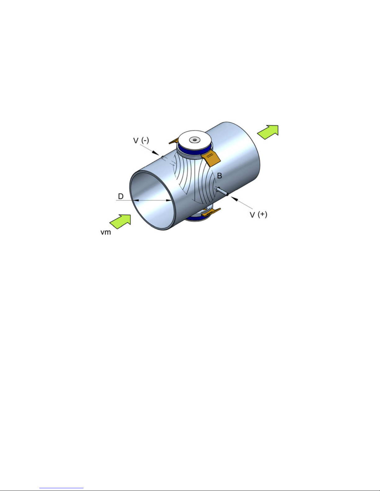
The FLOMID electromagnetic flowmeters with XL1 converter are based on Faraday’s
induction law.
When an electrically conductive liquid flows through a magnetic field, perpendicular to the
flow direction, it induces a voltage V proportional to the liquid velocity.
Two electrodes in contact with the liquid and positioned perpendicularly to the magnetic
field, sense this voltage V.
The electronic converter is based on the most advanced technology in digital signal
processing, in order to obtain accurate and reliable measurements.
The device provides the following features:
Coil excitation by means of pulsed signal to obtain a negligible zero offset.
Pulse and current output proportional to the flow rate and user programmable.
V = B·vm·D
Where:
V = Measured voltage in the electrodes
B = Magnetic field
vm= Average liquid velocity
D = Pipe diameter

6
4 INSTALLATION
This should be made in a point that guarantees that the pipe is always completely full.
Avoid high points of the pipes where air pockets usually form, or pipes with falling flow where
vacuums can form.
Partially full pipes can produce important reading errors.
2 RECEPTION
The FLOMID electromagnetic flowmeters are supplied conveniently packaged for their
protection during transportation and storage, together with their instructions manual for
installation and operation.
All the instruments are supplied tested in our flow rigs, obtaining the gain factor of each
sensor.
2.1 Unpacking
Unpack the instrument carefully, removing any remains of the packing from the inside of the
sensor. Do not remove the grease from the neck that couples to the electronics housing.
2.2 Storage temperatures
Sensors linings of: PTFE and PVDF -20ºC ...... +60ºC
PP and EBONITE -5ºC ...... +50ºC
3 HANDLING
It should always be done with care and without knocks.
The large diameter sensors have rings for holding the elevation elements. If the flowmeter is
held using slings, these should hold on the sensor and not on the electronics housing (see
drawing).

7
4.1 Sensor position
The most adequate position is with the electrodes in a horizontal plane. In this way, deposits
of particles on the electrodes are avoided.
Flow rate measurement with open discharge makes it necessary to install the flowmeter in a
pipe section with a siphon which avoids stagnation of air in the sensor.

8
If this distance is shorter, readings may be unstable.
In installations with turbulent flow it may be necessary to increase these distances.
4.2.1 Mixtures
If liquids of different conductivities are mixed it is necessary to install the sensor a minimum
of 30 DN from the point of mixture in order to obtain a uniform conductivity of the liquid and
stabilize the readings.
4.2 Straight pipe sections
They are necessary before and after the sensor. The minimum distances are the following:
Upstream 5 DN
Downstream 3 DN

9
4.3 Valves
Control valves or shut-off valves should always be installed downstream from the sensor to
assure that the pipe is always full of liquid.
4.5 Aeration
If there is a point where the level difference is higher than 5 m an air inlet valve should be
installed after the sensor to avoid a vacuum effect that could damage the sensor liner.
4.4 Pumps
Pumps should be mounted upstream from the sensor to avoid the suction of the pump
(vacuum) that could damage the sensor liner.
10
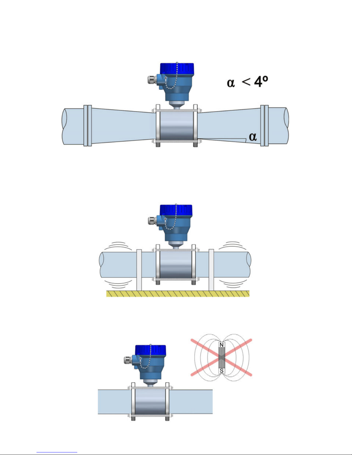
4.6 Reduction of DN
In installations where, due to reasons of the flow rate to be measured, a sensor of a smaller
DN than the pipe DN must be mounted, the reduction must be done with an angle smaller
than 4º to avoid turbulences that can give false readings.
If the angle cannot be so small, straight pipe sections indicated in 4.2 point must be kept.
4.7 Vibrations
Vibrations of the pipes should be avoided by anchoring the pipe before and after the sensor.
The vibration level should be less than 2.2 g in the range of 20 -150 Hz according to IEC
068-2-34.
4.8 Magnetic fields
Strong magnetic fields close to the sensor should be avoided.

11
4.9 Temperature
In open air installations it is recommended to install a protection to avoid direct sun light on
the flowmeter.
With thermally insulated pipes DO NOT insulate the sensor. High temperatures can damage
it.
The maximum liquid temperatures are shown on page 32.
5 MOUNTING
5.1 Parallelism
The maximum parallelism error must be less than 0.5 mm (Lmax—Lmin ≤ 0.5 mm).
12
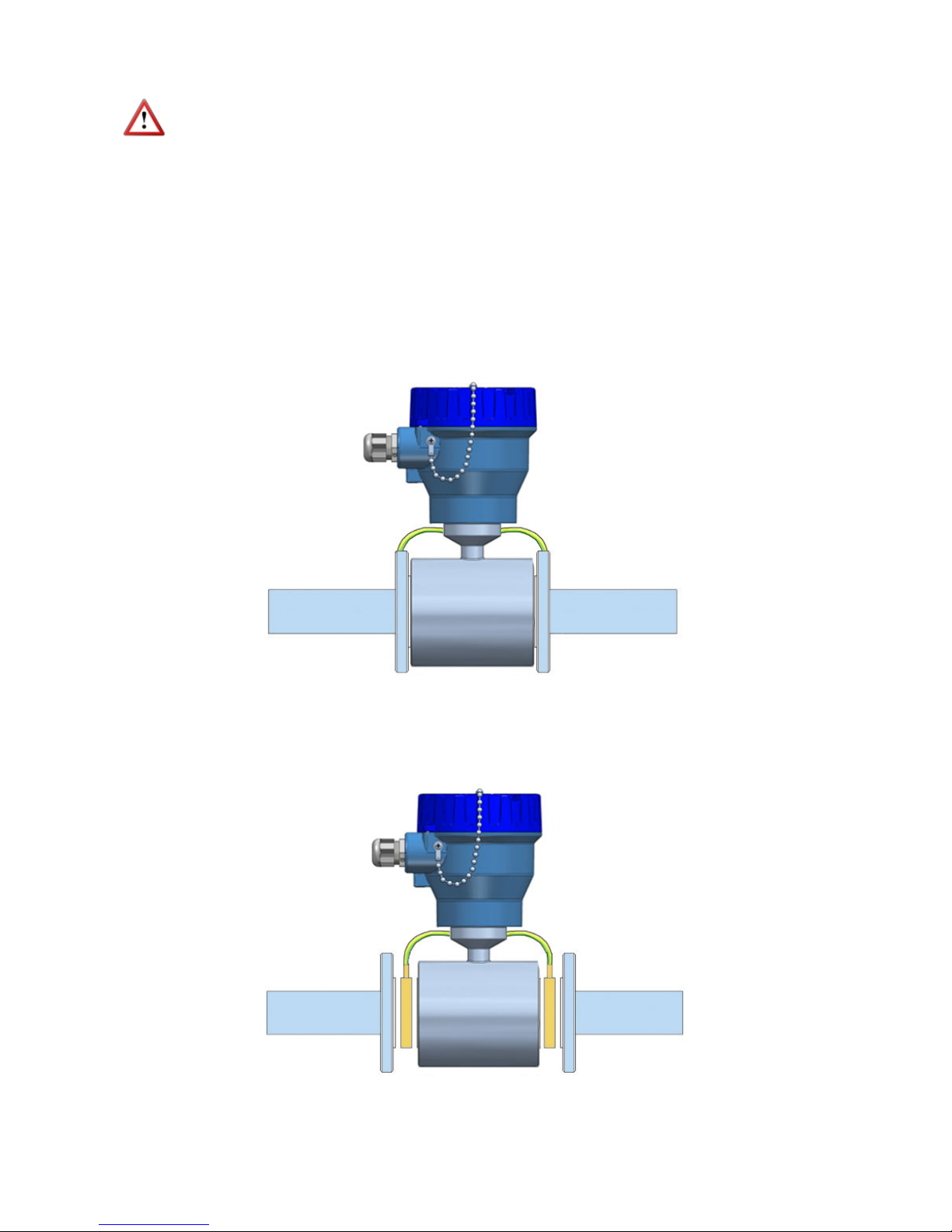
b) In the case of metallic pipes with internal lining or plastic pipes, connect the earth
cables to the earthing rings, supplied on request.
5.2 Sensor earth connection
To obtain correct operation the sensor should have its functional earth connected to a point
that is in direct contact with the liquid whose flow rate wants to be measured.
The earth cables should assure a good electrical contact. To obtain this, they should be well
screwed down and with a good contact on both sides of the sensor. It is important to
eliminate paint or coverings that act as insulation of the connection.
The functional earth connection should be used exclusively for the sensor given that parasitic
signals caused by other electrical equipment connected to this earth can cause malfunction
of the sensor.
The connection of the functional earth should be made as follows:
a) In the case of metallic pipes without internal lining connect the earth cables to the
counter flanges.
13
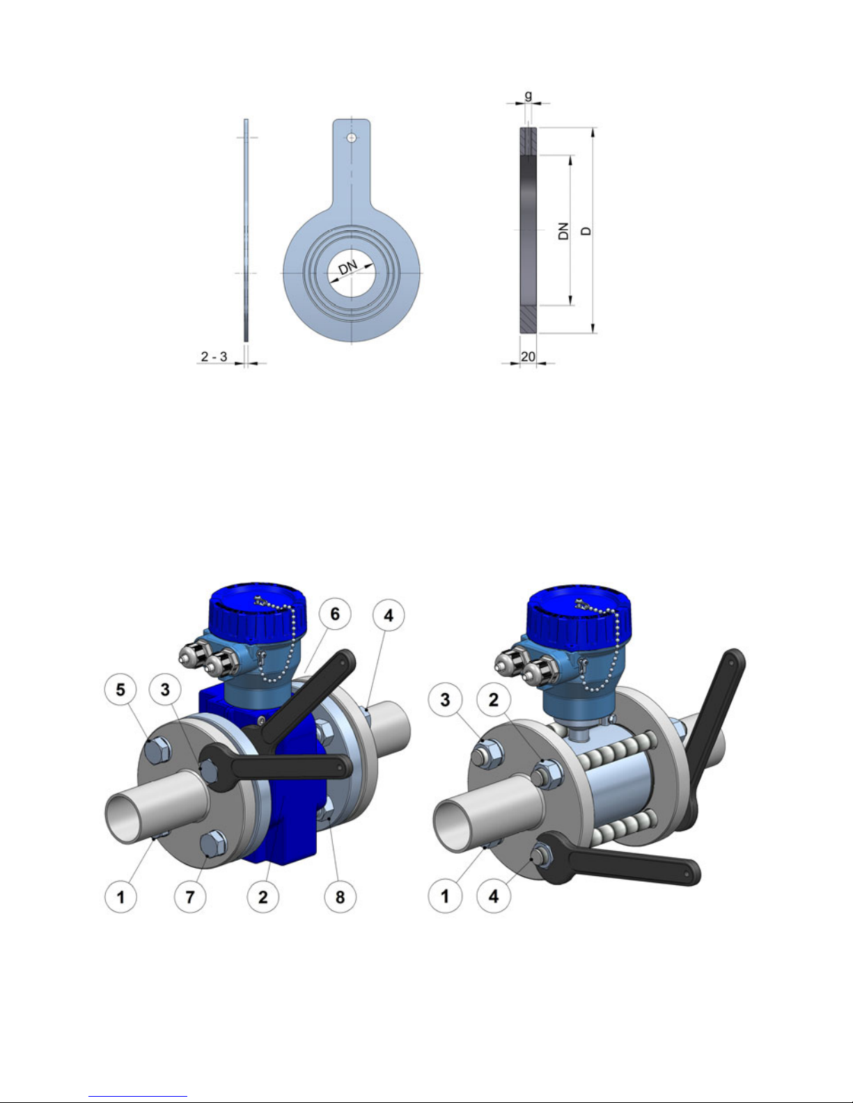
Earthing rings are supplied in two versions:
Metallic, disk in stainless steel EN 1.4404 (SS 316L), for liquids compatible with this material.
Plastic, with an electrode to make the contact with the liquid. The materials (plastic and
metal) depend on the working liquid.
5.3 Tightening
The tightening of the flange bolts should be done uniformly, following the sequence indicated
in the drawings according to the number of flange bolts.
PlasticMetallic
Dimensions in mm
14
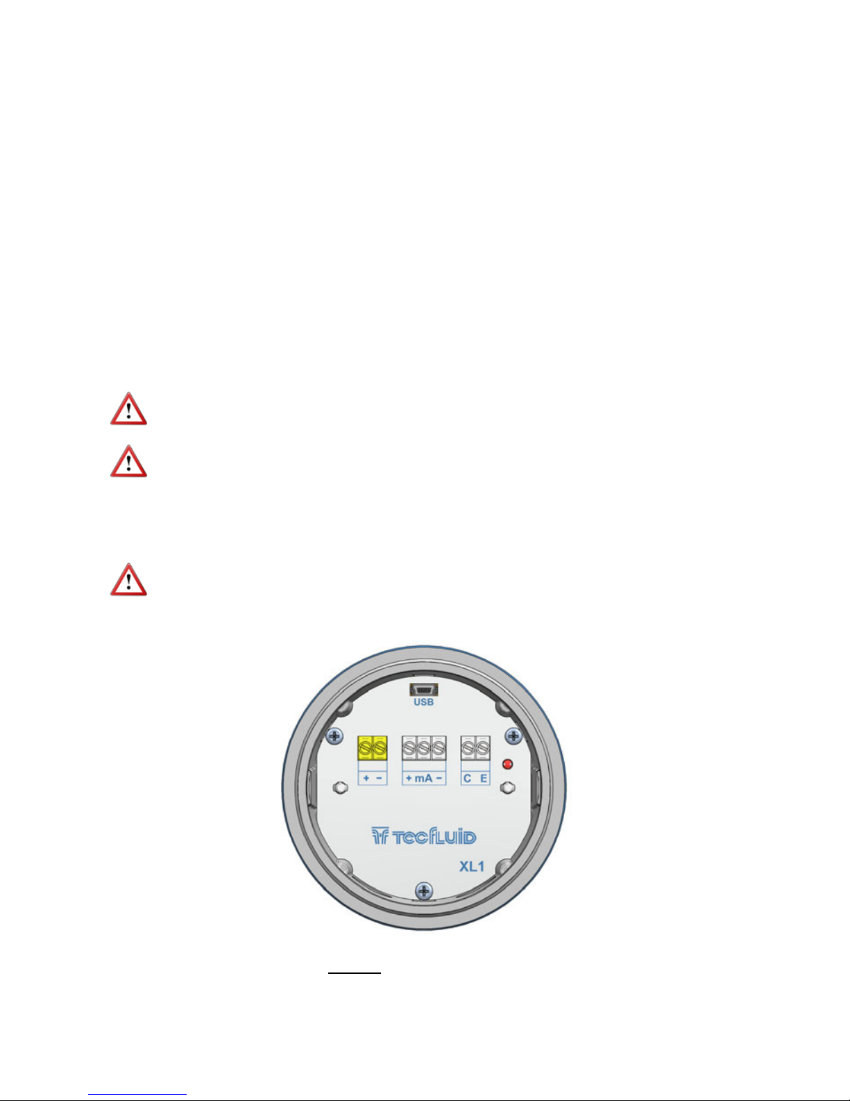
6 ELECTRICAL CONNECTION
For the electrical connection, the FLOMID flowmeter with XL1 converter is provided of
terminal strips. To help in the wiring of the equipment, the description of the terminals is
marked next to each terminal strip.
For the electrical installation it is recommended to use multiple conductor cables with
individual cable sections in the order of 0.25 to 0.5 mm2in order to make it easier to
connect.
Before starting the installation, check that the cable glands are the right size for the cables to
be used. This will guarantee the instrument will stay watertight. The cable glands used are
for cables with outside diameters between 5 mm and 12 mm.
It is better to maintain the cables with mains voltage (power supply) separated from the
cables with low level signals (4-20 mA or pulses).
To connect the cables, peel the outside insulation to free the inner cables. Then pass the
cables through the cable glands and screw down in the corresponding positions of the
terminal strip as indicated in the following point.
Grip carefully the cables with the cable glands to maintain the degree of protection.
Incorrect installation of the cable gland or inadequate cable placement can cause irreparable
damage to the converter.
IMPORTANT NOTE: To ensure smooth operation of the equipment, it is recommended
to make the electrical connection according to the following points:
For output signals, use shielded cable when possible.
Keep wires away from strong sources of noise.
6.1 Power supply wiring
Before starting the installation of the equipment, check that the supply voltage available is
the same as marked on the label of the flowmeter.
Terminal
+Power supply positive
-Power supply negative
15
When the device is powered, the led will be on.
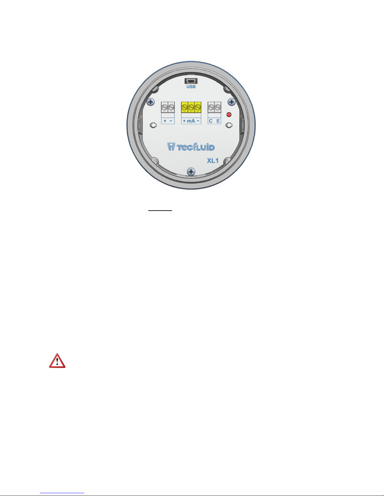
6.2 Analog output wiring
Terminal
+mA (positive, active output)
mA mA
-mA (negative, passive output)
The analog output is a current loop working linearly between 4 and 20 mA and proportional
to flow rate. When the converter detects empty pipe, the current loop gives a value of 3.6
mA, and when the flow rate is negative and the current output is configured as
unidirectional (see point 7.5.1), the loop will give 21 mA.
The analog output is galvanically isolated. It can be either active (which means that the
receiving device must be passive) or passive (which means that the receiver must supply the
power for the current loop). It is recommended to use a receptor with an input resistance of
less than 700 Ω to guarantee correct operation.
The configuration of the analog output mode (active or passive) is done by means of the
connection to the terminal strip. For active mode, terminals “+” and “mA” are connected. For
passive mode, terminals “mA” and “-” are connected.
NOTE: The analog output has protection against reversed polarity. Due to another
protection against over voltages, if a loop supply voltage of more than 32 V is connected the
converter may be damaged.

16
NOTE: Never connect the load between entre terminals “+” and “–”. The analog output
could be damaged.
6.3 Digital output wiring
Terminal
CCollector
EEmitter
Active output
Passive output

17
The digital output is opto-isolated. The terminals are the collector and emitter of a NPN
bipolar transistor.
If the equipment is configured as pulse mode (see page 26), the led will alternate between
green and red if there is a flow, and will remain green if there is no flow.
If it is configured as alarm mode (see page 26), the led will light red when the alarm is
activated and green when it is not.
In the case of using inductive loads, in order to protect the output transistor, the use of free
wheeling diodes is required.
Example. Connection with the load at the collector
Example. Connection with the load at the emitter
Coil
18
7ASSOCIATED SOFTWARE WINSMETER XL1
By means of this associated software, calibration and adjustment of the instrument can be
done in a comfortable and intuitive way.
Such software can be downloaded from the “Downloads” section of the Tecfluid S.A.
www.tecfluid.com/downloads
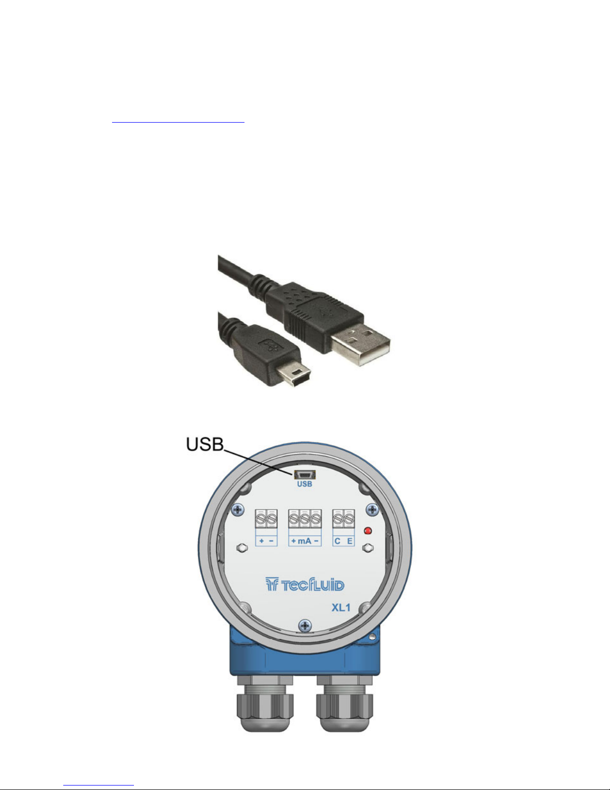
7.1 USB cable connection and software installation
Extract the files from the Winsmeter XL1.zip to a new system folder.
Execute the Setup.exe file and follow the steps for the installation.
In order to connect the converter to a computer an USB cable is required. This cable is type A
at one end and mini USB type B at the other, and it is readily available on the market.
The ends of the cables can be seen in the picture.
The USB connector is located at the opposite side of the cable glands.

19
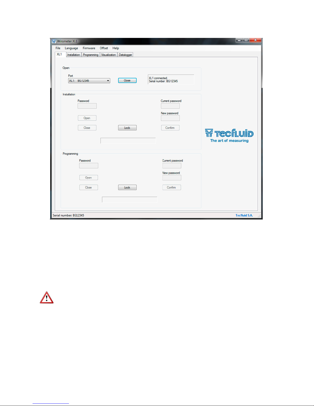
7.2 Port connection
In the "Port" section, choose the appropriate port for the converter. This will appear with the
name of the port followed by XL1 and its serial number. Then click "Open".
Connect the USB cable at one end to the converter and at the other to the computer where the
software is installed.
Power on the electronic converter.
Execute the program WinsmeterXL1 following the sequence Start – Programs – Tecfluid S.A. -
WinsmeterXL1.
20
Once the port is open, the button "Lock" is activated.
7.3 Password
The XL1 converter can be locked so that programming data can be modified only with previous
password access.
When the converter is locked, data can be read but not modified.
By default the device is unlocked. All data can be modified by means of the program
Winsmeter XL1.
To set a password access to a section (“Installation” or “Programming”), the section must be
unlocked. To do this, simply press the “Lock” button in the desired section.
Each section can be locked or unlocked independently. Passwords are equally independent for
each section.
This manual suits for next models
2
Table of contents
Popular Accessories manuals by other brands

SICK
SICK LBV 320 operating instructions

Geokon
Geokon 6160 installation manual

Rice Lake
Rice Lake IQ plus 390-DC installation manual

Manitowoc
Manitowoc G-0200 installation instructions

Dwyer Instruments
Dwyer Instruments TFP-LI Installation manual operating instructions

A&E Systems
A&E Systems 8500 user guide


Firetide
Firetide HotPort 5020-M Mesh Node installation guide

Infinity
Infinity INSTANTGO 5000 quick start guide

Notifier
Notifier SD-851TE Installation and maintenance instructions

ipf electronic
ipf electronic OT450521 manual

COMPX
COMPX Stock Locks C2018 Dimensional drawing

Eldom
Eldom KT100 instruction manual